Page 2456 of 2893

Cavity Wire Color Connect to
23-172Audio System
System Description (cont’d)
B1 BRN Auxiliary jack assembly
(AUX S GND)
B2 GRY Shield for terminals No")
�µ
�´
�����NAVIGATION UNIT CONNECTOR B (24P)
Cavity Wire Color Connect to
23-172Audio System
System Description (cont’d)
B1 BRN Auxiliary jack assembly
(AUX S GND)
B2 GRY Shield for terminals No. 1, No. 3, No. 11, No. 12, and
No. 13 (AUX SH GND)
B3 BLU Auxiliary jack assembly (AUX GND)
B8 LT BLU HandsFreeLink control unit (HFL MUTE)
B9 PNK HandsFreeLink control unit (TELM SIG )
B10 GRY Shield for terminals No. 11, No. 12, No. 23, and No. 24
(HFL/NAV COMM SH)
B11 GRN HandsFreeLink control unit (HFL/NAV COMM2)
B12 WHT HandsFreeLink control unit (HFL/NAV COMM4)
B13 YEL Auxiliary jack assembly (AUX L)
B14 GRN Auxiliary jack assembly (AUX R)
B15 WHT Auxiliary jack assembly (AUX DET)
B20 LT GRN HandsFreeLink control unit (HFL ICON)
B21 BLU HandsFreeLink control unit (TELM SIG )
B23 BLK HandsFreeLink control unit (HFL/NAV COMM1)
B24 RED HandsFreeLink control unit (HFL/NAV COMM3)
: The shielded wires have a heat-shrink tube insulating the outside of the wire. The color of the
insulating tube, typically black or dark gray, may
not match the color of the wire listed on the
schematic.
Wire side of female terminals
08/08/21 14:08:47 61SNR030_230_0175
ProCarManuals.com
DYNOMITE -2009-
Page 2457 of 2893

Cavity Wire Color Connect to NAVIGATION UNIT CONNECTOR G (3P)
Cavity Wire Color")
�´�´
�´ �´
�µ
�µ
�µ
�•�•�•
�•�•�•
�•�•�• �´
�����
�����
NAVIGATION UNIT CONNECTOR E (14P)
Cavity Wire Color Connect to NAVIGATION UNIT CONNECTOR G (3P)
Cavity Wire Color Connect to
23-173
E1 BLU XM receiver, USB adapter unit
(B)
E2 LT BLU XM receiver, USB adapter unit (SYS ACC)
E3 BRN Shield for terminals No. 9 and No. 10 (GA-NET BUS SH)
E4 GRY Shield for terminals No. 5, No. 6, No. 13, and No. 14
(SAT SH GND)
E5 WHT XM receiver, USB adapter unit (AUDIO R )
E6 RED XM receiver, USB adapter unit (AUDIO L )
E9 BLU XM receiver, USB adapter unit (GA-NET BUS )
E10 PNK XM receiver, USB adapter unit (GA-NET BUS )
E11 BLK XM receiver, USB adapter unit (GA-NET GND)
E13 BLK XM receiver, USB adapter unit (AUDIO R )
E14 GRN XM receiver, USB adapter unit (AUDIO L )
: The shielded wires have a heat-shrink tube insulating the outside of the wire. The color of the
insulating tube, typically black or dark gray, may
not match the color of the wire listed on the
schematic. G1 AM/FM/XM antenna (RF IN)
G2 Shield for terminal No. 1
(RF SH)
G3 AM/FM/XM antenna (ANT B)
(cont’d)
Wire side of female terminals Terminal side of female terminals
08/08/21 14:08:48 61SNR030_230_0176
ProCarManuals.com
DYNOMITE -2009-
Page 2458 of 2893
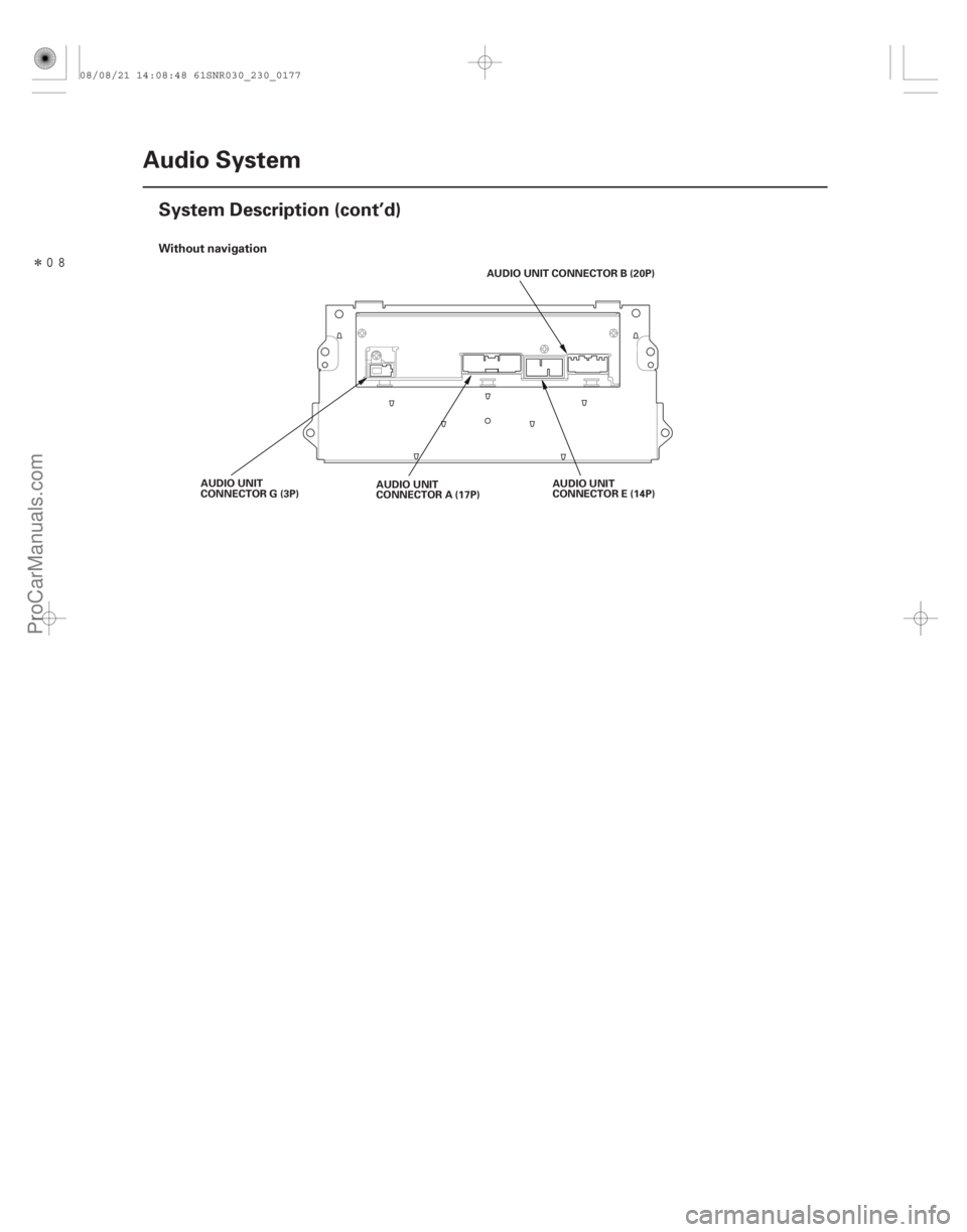
�����Without navigation
23-174Audio System
System Description (cont’d)
AUDIO UNIT CONNECTOR B (20P)
AUDIO UNIT
CONNECTOR E (14P)
AUDIO UNIT
CONNECTOR A (17P)
AUDIO UNIT
CONNECTOR G (3P)
08/08/21 14:08:48 61SNR030_230_0177
ProCarManuals.com
DYNOMITE -2009-
Page 2462 of 2893

Cavity Wire Color Connects to STEREO AMPLIFIER CONNECTOR B")
�´
�´ �´
�´
�´ �´
�´
�´ �µ
�µ �µ
�µ
�µ �µ
�µ �´
�´
�´�´
�µ
�µ
�µ�µ
��
�� ��
��
STEREO AMPLIFIER CONNECTOR A (20P)
Cavity Wire Color Connects to STEREO AMPLIFIER CONNECTOR B (14P)
Cavity Wire Color Connects to
23-178Audio System
System Description (cont’d)
A1 PNK Right tweeter ( )
A2 GRY Front passenger’s door speaker
()
A3 Driver’s door speaker ( )
A4 RED Left tweeter ( )
A5 GRN Subwoofer ( )
A7 BLU Right rear speaker ( )
A8 GRY Left rear speaker ( )
A9 PUR Multiplex integrated control unit (MICU) (ACC RADIO)
A10 LT GRN B (Main stereo power supply)
A11 BLU Right tweeter ( )
A12 BRN Front passenger’s door speaker ()
A13 PNK Driver’s door speaker ( )
A14 GRN Left tweeter ( )
A15 RED Subwoofer ( )
A17 ORN Right rear speaker ( )
A18 BRN Left rear speaker ( )
A20 BLK Ground (G 601) B1 BLU Navigation unit (FL SIG )
B2 BRN Shield for terminals No. 1 and
No. 8 (FL SH GND)
B3 BLK Navigation unit (RL SIG )
B4 BLU Navigation unit (FR SIG )
B5 GRY Shield for terminals No. 4 and No. 11 (FR SH GND)
B6 LT GRN Navigation unit (RR SIG )
B7 LT BLU Navigation unit (AMP ON)
B8 RED Navigation unit (FL SIG )
B9 GRN Shield for terminals No. 3 and No. 10 (RL SH GND)
B10 WHT Navigation unit (RL SIG )
B11 PNK Navigation unit (FR SIG )
B12 YEL Shield for terminals No. 6 and No. 13 (RR SH GND)
B13 PUR Navigation unit (RR SIG )
: The shielded wires have a heat-shrink tube insulating the outside of the wire. The color of the
insulating tube, typically black or dark gray, may
not match the color of the wire listed on the
schematic.
Wire side of female terminals Wire side of female terminals
08/08/21 14:09:43 61SNR030_230_0181
ProCarManuals.com
DYNOMITE -2009-
Page 2463 of 2893
��
��
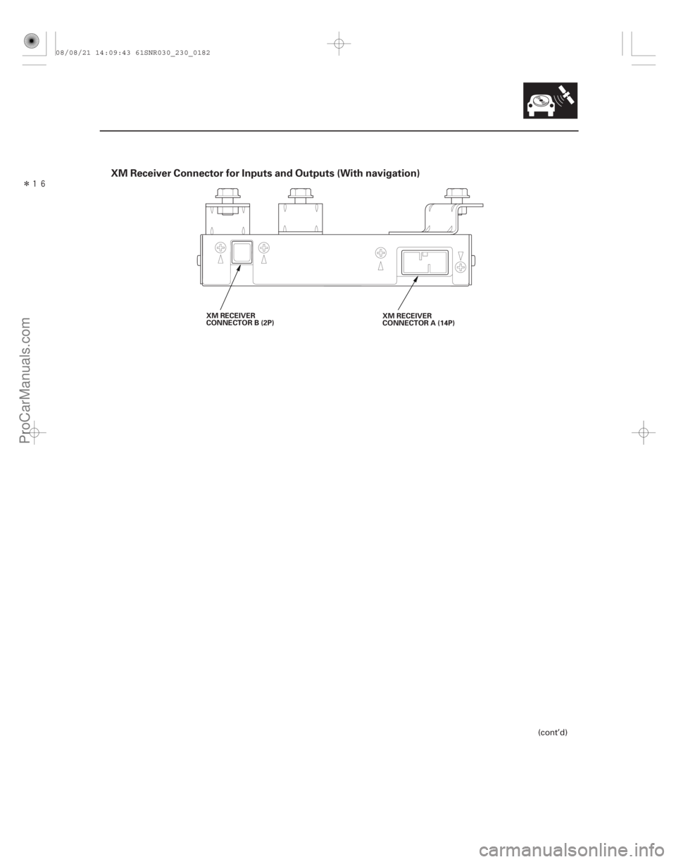
XM Receiver Connector for Inputs and Outputs (With navigation)
23-179
XM RECEIVER
CONNECTOR B (2P)XM RECEIVER
CONNECTOR A (14P)
(cont’d)
08/08/21 14:09:43 61SNR030_230_0182
ProCarManuals.com
DYNOMITE -2009-
Page 2464 of 2893

Cavity Wire Color Connect to XM RECEIVER CONNECTOR B (2P)
Cavity Wire Color Connect to
23-180Audio Sy")
�´�´
�´ �´
�µ
�µ
�µ
�•�•�•
�•�•�•
��
��
��
��
XM RECEIVER CONNECTOR A (14P)
Cavity Wire Color Connect to XM RECEIVER CONNECTOR B (2P)
Cavity Wire Color Connect to
23-180Audio System
System Description (cont’d)
A1 BLU Navigation unit, USB adapter
unit ( B)
A2 LT BLU Navigation unit, USB adapter unit (SYS ACC)
A3 BRN Shield for terminals No. 9 and No. 10 (GA-NET SH GND)
A5 WHT Navigation unit, USB adapter unit (SAT R )
A6 RED Navigation unit, USB adapter unit (SAT L )
A9 BLU Navigation unit, USB adapter unit (GA-NET BUS )
A10 PNK Navigation unit, USB adapter unit (GA-NET BUS )
A11 BLK Navigation unit, USB adapter unit (GND)
A13 BLK Navigation unit, USB adapter unit (SAT R )
A14 GRN Navigation unit, USB adapter unit (SAT L )
: The shielded wires have a heat-shrunk tube insulating the outside of the wire. The color of the
insulating tube, typically black or dark gray, may
not match the color of the wire listed on the
schematic. B1 Satellite signal antenna (SAT/
TER)
B2 Shield for terminal No. 1 (GND SH)
Wire side of female terminals Terminal side of female terminals
08/08/21 14:09:43 61SNR030_230_0183
ProCarManuals.com
DYNOMITE -2009-
Page 2466 of 2893

Cavity Wire Color Connect to USB ADAPTER
UNIT CON")
�´�´
�´ �´
�µ
�µ
�µ
�•�•�•
�•�•�• �µ
�•�•�• �´
�•�•�•
�•�•�•
�����
����
USB ADAPTER
UNIT CONNECTOR A (14P)
Cavity Wire Color Connect to USB ADAPTER
UNIT CONNECTOR B (5P)
Cavity Wire Color Connect to
23-182Audio System
System Description (cont’d)
A1 BLU Navigation unit , audio unit ,
XM receiver ( B)
A2 LT BLU Navigation unit , audio unit , XM receiver (SYS ACC)
A3 BRN Shield for terminals No. 9 and No. 10 (GA-NET BUS SH)
A4 GRY Shield for terminals No. 5, No. 6, No. 13, and No. 14
(AUDIO SH)
A5 WHT Navigation unit , audio unit , XM receiver (AUDIO R )
A6 RED Navigation unit , audio unit , XM receiver (AUDIO L )
A9 BLU Navigation unit , audio unit , XM receiver (GA-NET BUS )
A10 PNK Navigation unit , audio unit , XM receiver (GA-NET BUS )
A11 BLK Navigation unit , audio unit , XM receiver (GND)
A13 BLK Navigation unit , audio unit , XM receiver (AUDIO R )
A14 GRN Navigation unit, XM receiver (AUDIO L )
1: The shielded wires have a heat-shrunk tube insulating the outside of the wire. The color of the
insulating tube, typically black or dark gray, may
not match the color of the wire listed on the
schematic.
2: With navigation
3: Without navigation B1 USB adapter (USB VBUS)
B2 USB adapter (USB DATA )
B3 USB adapter (USB DATA )
B4 USB adapter (USB GND)
B5 Shield for terminals No. 1,
No.2,No.3,andNo.4(USB
SH)23
23
1
1
23
23
23
23
23
23
Wire side of female terminals Terminal side of female terminals
08/08/21 14:09:44 61SNR030_230_0185
ProCarManuals.com
DYNOMITE -2009-
Page 2467 of 2893
����������
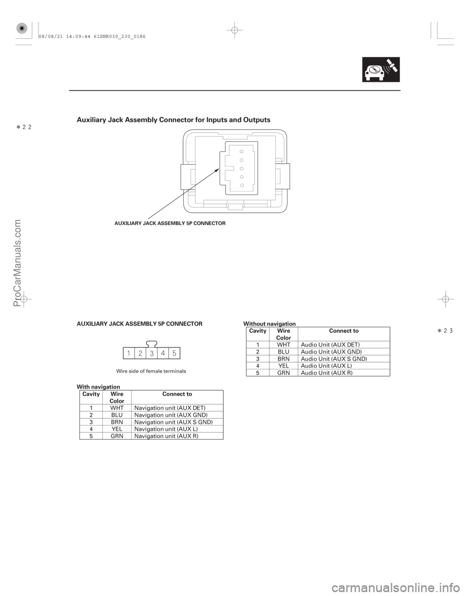
Auxiliary Jack Assembly Connector for Inputs and Outputs
AUXILIARY JACK ASSEMBLY 5P CONNECTOR
With navigationCavity Wire Color Connect to Without navigation
Cavity Wire Color Connect to
23-183
AUXILIARY JACK ASSEMBLY 5P CONNECTOR
1 WHT Navigation unit (AUX DET)
2 BLU Navigation unit (AUX GND)
3 BRN Navigation unit (AUX S GND)
4 YEL Navigation unit (AUX L)
5 GRN Navigation unit (AUX R) 1 WHT Audio Unit (AUX DET)
2 BLU Audio Unit (AUX GND)
3 BRN Audio Unit (AUX S GND)
4 YEL Audio Unit (AUX L)
5 GRN Audio Unit (AUX R)
Wire side of female terminals
08/08/21 14:09:44 61SNR030_230_0186
ProCarManuals.com
DYNOMITE -2009-