Page 1631 of 2893
���
�´
�µ
�µ �µ
�µ
YES
NO YES
NO
19-139
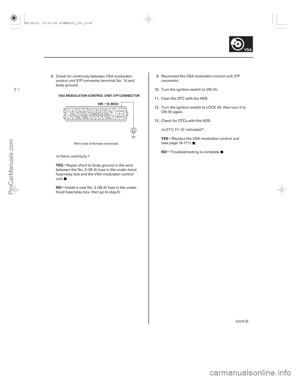
MR B (RED)
VSA MODULATOR-CONTROL UNIT 37P CONNECTOR
8. Check for continuity between VSA modulator-
control unit 37P connector terminal No. 14 and
body ground.
Repair short to body ground in the wire
between the No. 3 (30 A) fuse in the under-hood
fuse/relay box and the VSA modulator-control
unit.
Install a new No. 3 (30 A) fuse in the under-
hood fuse/relay box, then go to step 9. 9. Reconnect the VSA modulator-control unit 37P
connector.
10. Turn the ignition switch to ON (II).
11. Clear the DTC with the HDS.
12. Turn the ignition switch to LOCK (0), then turn it to ON (II) again.
13. Check for DTCs with the HDS.
Replace the VSA modulator-control unit
(see page 19-171).
Troubleshooting is complete.
(cont’d)
Wire side of female terminals
Is there continuity? I s DT C 5 1-12 i nd i cat ed ?
08/08/21 15:05:56 61SNR030_190_0139
ProCarManuals.com
DYNOMITE -2009-
Page 1632 of 2893
����
�´
�µ
�µ �µ
�µ
YES
NO YES
NO
DTC 52-12:
19-14019-140VSA System Components
DTC Troubleshooting (cont’d)
MR B (RED)
VSA MODULATOR-CONTROL U")
����
�(�#�'��������� �����
�������'�����
���������)����
�´
�µ
�µ �µ
�µ
YES
NO YES
NO
DTC 52-12:
19-14019-140VSA System Components
DTC Troubleshooting (cont’d)
MR B (RED)
VSA MODULATOR-CONTROL UNIT 37P CONNECTOR
14. Disconnect the VSA modulator-control unit 37P
connector (see step 2 on page 19- 171).
15. Measure the voltage between VSA modulator- control unit 37P connector terminal No. 14 and
body ground.
Check for loose terminals in the VSA
modulator-control unit 37P connector. If necessary,
substitute a known-good VSA modulator-control
unit (see page 19-171), and retest.
Repair open in the wire between the No. 3
(30 A) fuse in the under-hood fuse/relay box and
the VSA modulator-control unit. 1. Turn the ignition switch to ON (II).
2. Clear the DTC with the HDS.
3. Turn the ignition switch to LOCK (0), then turn it to
ON (II) again.
4. Operate any one of the four solenoids, as listed, in the VSA FUNCTION TEST five times with the HDS.
-LFT FT SOLENOID
-RT FT SOLENOID
-LFT REAR SOLENOID
-RT REAR SOLENOID
5. Check for DTCs with the HDS.
Replace the VSA modulator-control unit
(see page 19-171).
Intermittent failure, the system is OK at this
time.Motor Stuck OFF
Wire side of female terminals
Is there battery voltage? Is DTC 52-12 indicated?
08/08/21 15:05:56 61SNR030_190_0140
ProCarManuals.com
DYNOMITE -2009-
Page 1653 of 2893
.
10. Me")
��������
�µ
�µ
�µ
�µ
YES
NO
YES
NO
19-161
YAW RATE-LATERAL ACCELERATION SENSOR
5P CONNECTOR
YEL YAW RATE-LATERAL ACCELERATION SENSOR
5P CONNECTOR
BLK
9. Turn the ignition switch to ON (II).
10. Measure the voltage between yaw rate-lateral acceleration sensor 5P connector terminal No. 1
and body ground.
Go to step 11.
Check the No. 4 (7.5 A) fuse in the under-dash
fuse/relay box. If the fuse is OK, repair open in the
wirebetweentheNo.4(7.5A)fuseandyawrate-
lateral acceleration sensor. 11. Turn the ignition switch to LOCK (0).
12. Reconnect the yaw rate-lateral acceleration sensor
5P connector.
13. Turn the ignition switch to ON (II).
14. Measure the voltage between yaw rate-lateral acceleration sensor 5P connector terminal No. 5
and body ground.
Replace the yaw rate-lateral acceleration
sensor (see page 19-169).
Repair open in the wire between the yaw rate-
lateral acceleration sensor and body ground
(G602).
Wire side of female terminals
Wire side of female terminals
Is there battery voltage?Is t her e 0.1 V or l ess?
08/08/21 15:06:43 61SNR030_190_0161
ProCarManuals.com
DYNOMITE -2009-
Page 1655 of 2893
���
�´
�µ
�µ �µ
�µ
�µ
�µ
DTC 112-01:
YES
NO YES
NO
YES
NO
19-163
VSA MODULATOR-CONTROL UNIT 37P CONNECTOR
FSR B (WHT)
VSA MODULATOR-")
���
����
����
�(�#�'��������� �����
�������(�
�����
�������)���
�´
�µ
�µ �µ
�µ
�µ
�µ
DTC 112-01:
YES
NO YES
NO
YES
NO
19-163
VSA MODULATOR-CONTROL UNIT 37P CONNECTOR
FSR B (WHT)
VSA MODULATOR-CONTROL UNIT 37P CONNECTOR
IG1 (GRY)
VSA MODULATOR-CONTROL UNIT 37P CONNECTOR IG1 (GRY)
Central Processing Unit (CPU)
Internal Circuit Malfunction
1. Turn the ignition switch to ON (II).
2. Clear the DTC with the HDS.
3. Turn the ignition switch to LOCK (0).
4. Disconnect the VSA modulator-control unit 37P
connector (see step 2 on page 19- 171).
5. Measure the voltage between VSA modulator- control unit 37P connector terminal No. 13 and
body ground.
Go to step 6.
Check the battery performance (see page
22-67), and troubleshoot the alternator and
regulator circuit (see page 4-28). 6. Measure the voltage between VSA modulator-
control unit 37P connector terminal No. 28 and
body ground.
Go to step 7.
Repair short to power in the wire between the
No. 4 (7.5 A) fuse in the under-dash fuse/relay box
and the VSA modulator-control unit.
7. Turn the ignition switch to ON (II).
8. Measure the voltage between VSA modulator- control unit 37P connector terminal No. 28 and
body ground.
Check for loose terminals in the VSA
modulator-control unit 37P connector. If necessary,
substitute a known-good VSA modulator-control
unit (see page 19-171), and retest.
Repair open in the wire between the No. 4
(7.5 A) fuse in the under-dash fuse/relay box and
the VSA modulator-control unit.
Wire side of female terminals
Wire side of female terminals
Wire side of female terminals
Is there battery voltage? Is there 0 V ?
Is there battery voltage?
08/08/21 15:06:44 61SNR030_190_0163
ProCarManuals.com
DYNOMITE -2009-
Page 1658 of 2893
����
�µ
�µ
�µ
�µ �µ
�µ
�µ
�µ
ABS indicator, brake system indicator, and
VSA indicator do not go off
YES
NO
YES
NO YES
NO
YES
NO
19-")
����
�����
�(�#�'���������������
�����������������������)����
�µ
�µ
�µ
�µ �µ
�µ
�µ
�µ
ABS indicator, brake system indicator, and
VSA indicator do not go off
YES
NO
YES
NO YES
NO
YES
NO
19-166
VSA System Components
Symptom Troubleshooting (cont’d)
VSA MODULATOR-CONTROL UNIT 37P CONNECTOR
IG1 (GRY) VSA MODULATOR-CONTROL UNIT 37P CONNECTOR
IG1 (GRY)
1. Turn the ignition switch to LOCK (0).
2. Check the No. 4 (7.5 A) fuse in the under-dash fuse/relay box.
Go to step 3.
Reinstall the checked fuse, then go to step 9.
3. Disconnect the VSA modulator-control unit 37P connector (see step 2 on page 19- 171).
4. Disconnect the yaw rate-lateral acceleration sensor 5P connector (see page 19- 169).
5. Check for continuity between VSA modulator- control unit 37P connector terminal No. 28 and
body ground.
Repair short to body ground in the wire
between the No. 4 (7.5 A) fuse in the under-dash
fuse/relay box and the VSA modulator-control unit
or the yaw rate-lateral acceleration sensor.
Install a new No. 4 (7.5 A) fuse in the under-
dashfuse/relaybox,thengotostep6. 6. Reconnect all connectors.
7. Turn the ignition switch to ON (II).
8. Check the ABS indicator, the brake system
indicator and the VSA indicator for several seconds
when the ignition switch is tuned to ON (II).
Troubleshooting is complete.
Replace the VSA modulator-control unit
(see page 19-171).
9. Disconnect the VSA modulator-control unit 37P connector (see step 2 on page 19-171).
10. Turn the ignition switch to ON (II).
11. Measure the voltage between VSA modulator- control unit 37P connector terminal No. 28 and
body ground.
Go to step 12.
Repair open in the wire between the No. 4
(7.5 A) fuse in the under-dash fuse/relay box and
the VSA modulator-control unit.
12. Turn the ignition switch to LOCK (0).
Wire side of female terminals Wire side of female terminals
Isthefuseblown?
Is there continuity? Does t he i nd i cat or s come on t hen go of f ?
Is there battery voltage?
08/08/21 15:06:44 61SNR030_190_0166
ProCarManuals.com
DYNOMITE -2009-
Page 1659 of 2893
 36P
Connector Terminal
19-167
VSA MODULATOR-CON")
�����
���������
�´
�µ
�µ
�µ
�µ �µ
�µ
YES
NO
YES
NO Sign
YES
NO
VSA Modulator- control Unit 37P
Connector Terminal Gauge Control
Module (Tach) 36P
Connector Terminal
19-167
VSA MODULATOR-CONTROL UNIT 37P CONNECTOR
GND (BLK)
VSA MODULATOR-CONTROL UNIT 37P CONNECTOR FSR B (WHT) VSA MODULATOR-CONTROL UNIT 37P CONNECTOR
CAN-L (RED)CAN-L (RED)
CAN-H (WHT) CAN-H (WHT)
GAUGE CONTROL MODULE (TACH) 36P CONNECTOR
13. Check for continuity between VSA modulator- control unit 37P connector terminal No. 36 and
body ground.
Go to step 14.
Repair open in the wire between the VSA
modulator-control unit and body ground (G 202).
14. Measure the voltage between VSA modulator- control unit 37P connector terminal No. 13 and
body ground.
Go to step 15.
Repair open in the wire between the No. 3
(40 A) fuse in the under-hood fuse/relay box and
the VSA modulator-control unit. 15. Disconnect the gauge control module (tach) 36P
connector.
16. Check for continuity between VSA modulator- control unit 37P connector terminal and gauge
control module (tach) 36P connector terminal (see
table).
CAN-L No. 1 No. 19
CAN-H No. 15 No. 1
Check for loose terminals in the VSA
modulator-control unit 37P connector. If necessary,
substitute a known-good VSA modulator-control
unit (see page 19-171), and retest.
Repair open in the wire between the gauge
control module (tach) and the VSA modulator-
control unit.
Wire side of female terminals
Wire side of female terminals Wire side of female terminals
Wire side of female terminals
Is there continuity?
Is there battery voltage? Is there continuity?
08/08/21 15:06:45 61SNR030_190_0167
ProCarManuals.com
DYNOMITE -2009-
Page 1786 of 2893
���
���
����
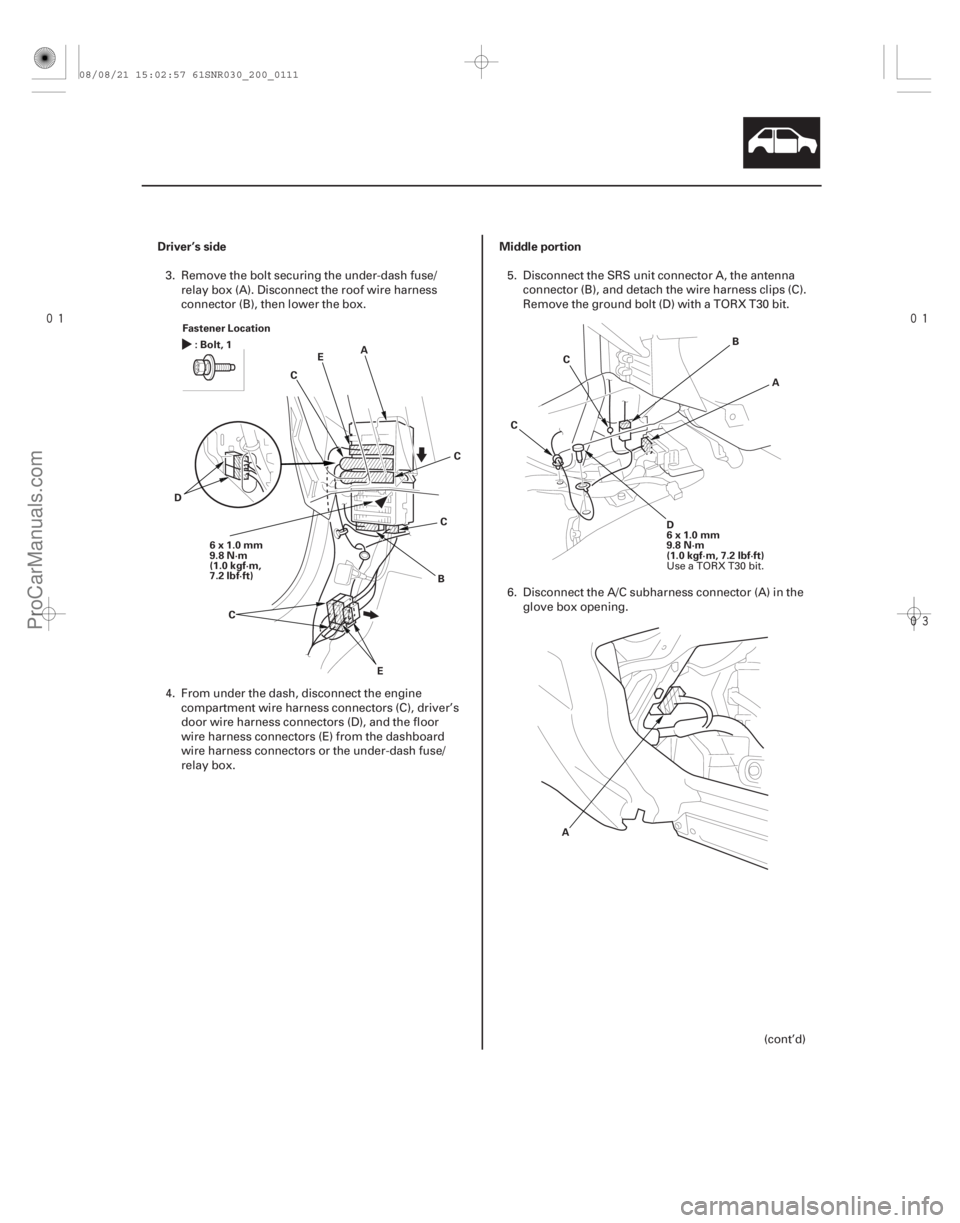
Driver’s side Middle portion
20-109
Fastener Location
6x1.0mm
9.8 N·m
(1.0 kgf·m,
7.2 lbf·ft) A
C
B
D E
:Bolt,1
C
E C
C A
B
D
6x1.0mm
9.8 N·m
(1.0 kgf·m, 7.2 lbf·ft)
C
C
A
3. Remove the bolt securing the under-dash fuse/ relay box (A). Disconnect the roof wire harness
connector (B), then lower the box.
4. From under the dash, disconnect the engine compartment wire harness connectors (C), driver’s
door wire harness connectors (D), and the floor
wire harness connectors (E) from the dashboard
wire harness connectors or the under-dash fuse/
relay box. 5. Disconnect the SRS unit connector A, the antenna
connector (B), and detach the wire harness clips (C).
Remove the ground bolt (D) with a TORX T30 bit.
6. Disconnect the A/C subharness connector (A) in the glove box opening.
(cont’d)
Use a TORX T30 bit.
08/08/21 15:02:57 61SNR030_200_0111
ProCarManuals.com
DYNOMITE -2009-
Page 1882 of 2893
�����
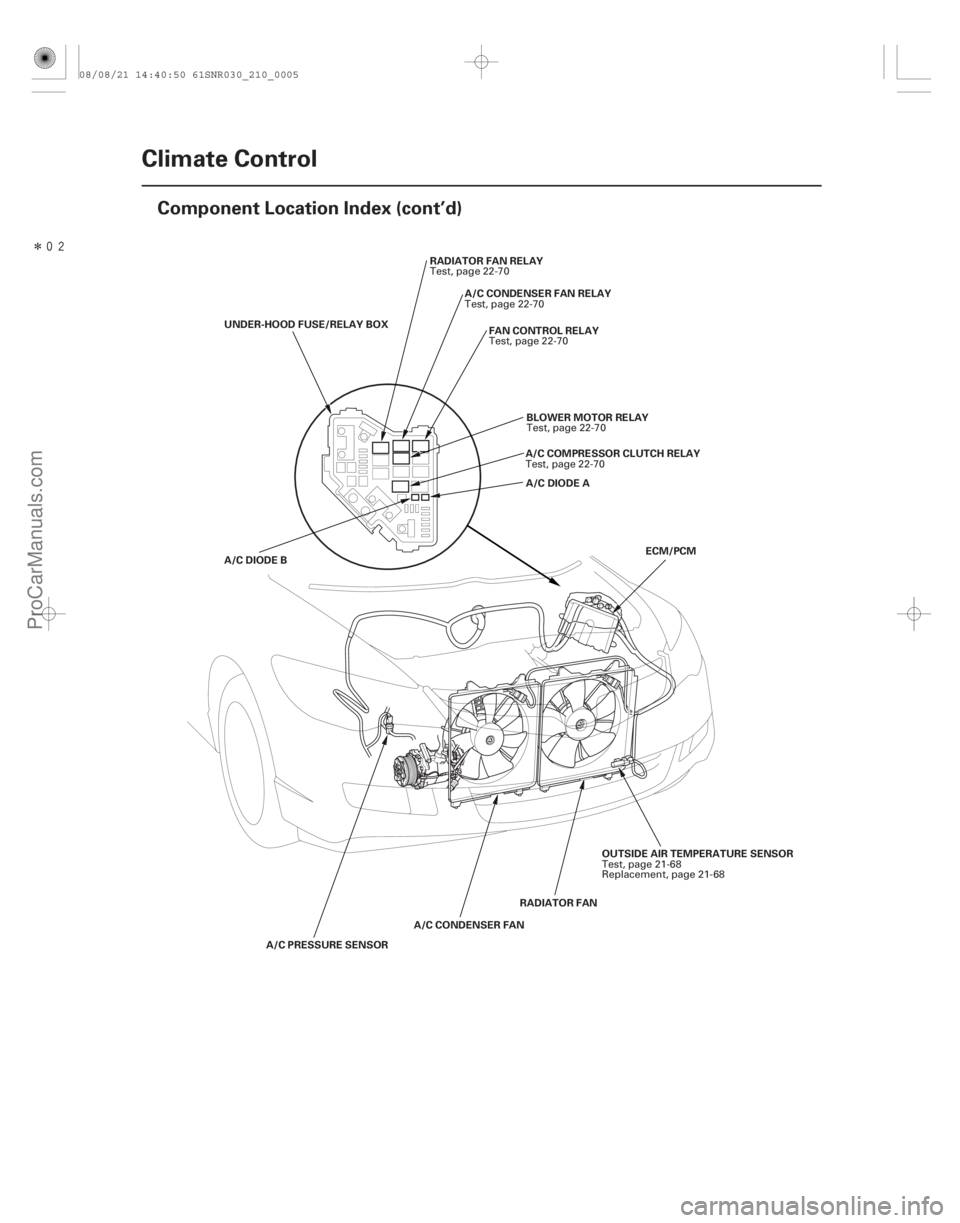
21-4Climate Control
Component Location Index (cont’d)
A/C PRESSURE SENSOR
RADIATOR FAN
A/C CONDENSER FAN A/C CONDENSER FAN RELAY
BLOWER MOTOR RELAY
RADIATOR FAN RELAY
A/C COMPRESSOR CLUTCH RELAY
FAN CONTROL RELAY
UNDER-HOOD FUSE/RELAY BOX
A/C DIODE B A/C DIODE A
ECM/PCM
OUTSIDE AIR TEMPERATURE SENSOR
Test, page 22-70
Test, page 22-70
Test, page 22-70
Test, page 22-70
Test, page 22-70
Test, page 21-68
Replacement, page 21-68
08/08/21 14:40:50 61SNR030_210_0005
ProCarManuals.com
DYNOMITE -2009-