Page 5018 of 5135

I42014(3)(1)
I42013
(5)
(1) 05–312
– DIAGNOSTICSCRUISE CONTROL SYSTEM (2AZ–FSE)(From
February, 2004)
AVENSIS REPAIR MANUAL SUPPLEMENT
(RM1098E)
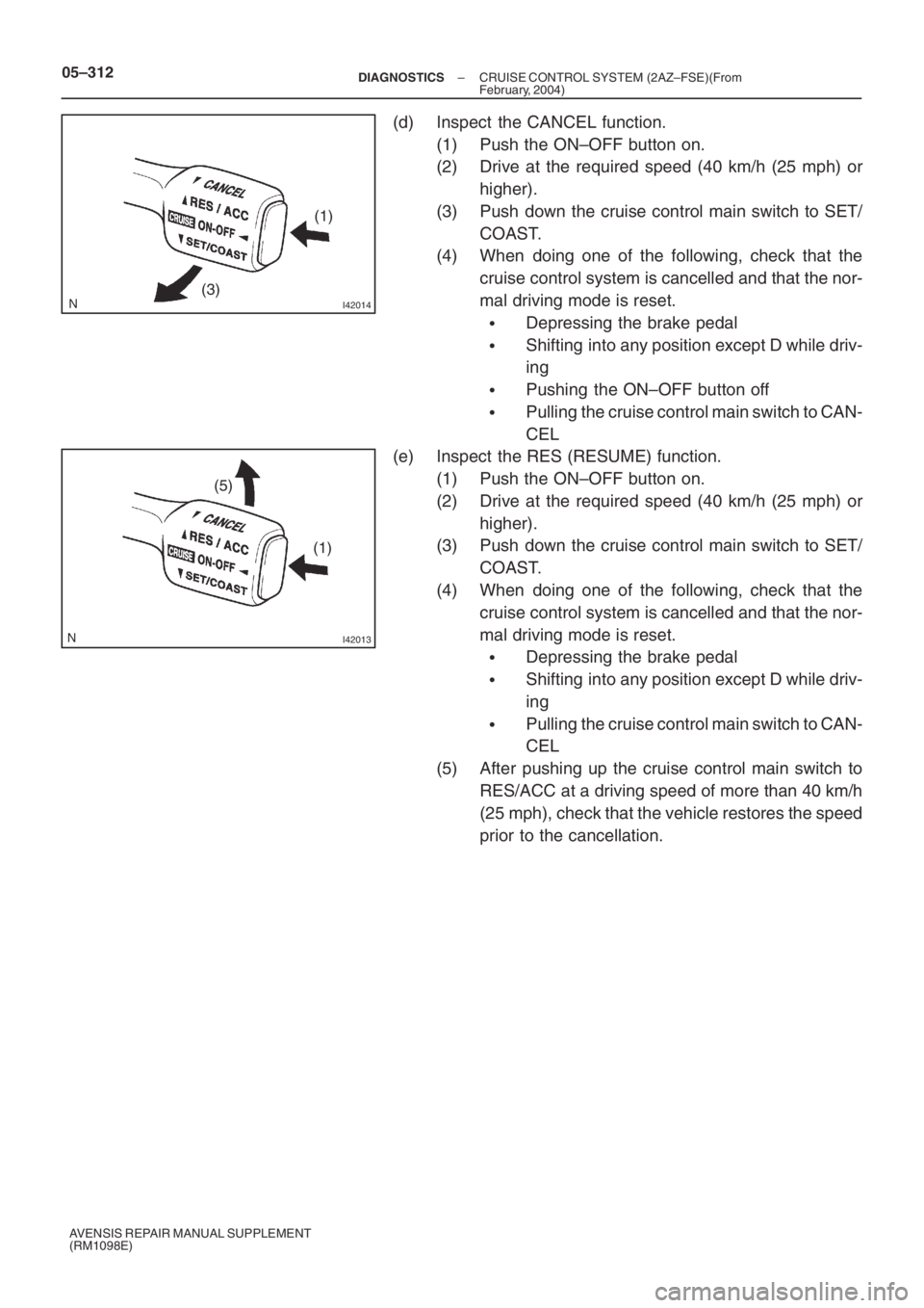
(d) Inspect the CANCEL function.
(1) Push the ON–OFF button on.
(2) Drive at the required speed (40 km/h (25 mph) or
higher).
(3) Push down the cruise control main switch to SET/
COAST.
(4) When doing one of the following, check that the
cruise control system is cancelled and that the nor-
mal driving mode is reset.
�Depressing the brake pedal
�Shifting into any position except D while driv-
ing
�Pushing the ON–OFF button off
�Pulling the cruise control main switch to CAN-
CEL
(e) Inspect the RES (RESUME) function.
(1) Push the ON–OFF button on.
(2) Drive at the required speed (40 km/h (25 mph) or
higher).
(3) Push down the cruise control main switch to SET/
COAST.
(4) When doing one of the following, check that the
cruise control system is cancelled and that the nor-
mal driving mode is reset.
�Depressing the brake pedal
�Shifting into any position except D while driv-
ing
�Pulling the cruise control main switch to CAN-
CEL
(5) After pushing up the cruise control main switch to
RES/ACC at a driving speed of more than 40 km/h
(25 mph), check that the vehicle restores the speed
prior to the cancellation.
Page 5019 of 5135
05ADI–06
–
DIAGNOSTICS CRUISE CONTROL SYSTEM (2AZ–FSE)(From
February, 2004)05–303
AVENSIS REPAIR MANUAL SUPPLEMENT
(RM1098E)
CRUISE CONTROL SYSTEM (2AZ–FSE)(From February,
2004)
HOW TO PROCEED WITH TROUBLESHOOTING
1 VEHICLE BROUGHT TO WORKSHOP
2 CUS TOMER PROBLEM ANA LYSIS ( SEE PAGE 05–305 )
3 CHECK AND CLEAR DTCS ( SEE PAGE 05–306 )
4 PROBLEM SYMPTOM CONFIRMATION
SYMPTOM DOES NOT OCCUR (GO TO STEP 5)
SYMPTOM OCCURS (GO TO STEP 6)
5 SYMP TOM SIMUL ATION ( SEE PAGE 01–22 )
6 DTC CHECK ( SEE PAGE 05–306 )
(a) Check for cruise control system DTC output.
TROUBLE CODE (GO TO STEP 7)
NORMAL SYSTEM CODE (GO TO STEP 8)
7 DTC CHART ( SEE PAGE 05–313 )
8 PROBLEM SYMPTOMS TABLE ( SEE PAGE 05–316 )
9 CIRCUIT INSPECTION ( SEE PAGE 05–317 T O 05–328 )
Page 5020 of 5135
05–304–
DIAGNOSTICS CRUISE CONTROL SYSTEM (2AZ–FSE)(From
February, 2004)
AVENSIS REPAIR MANUAL SUPPLEMENT
(RM1098E)
10 TERMINAL OF ECM ( SEE PAGE 05–315 )
11 IDENTIFICATION OF PROBLEM
12 REPAIR OR REPLACE
13 CONFIRMATION TEST
END
HINT:
The intelligent tester II can be used at the following diagnostic steps; 3,\
6, 9 and 13.
Page 5087 of 5135

–
DIAGNOSTICS CRUISE CONTROL SYSTEM (2AZ–FSE)(From
February, 2004)05–327
AVENSIS REPAIR MANUAL SUPPLEMENT
(RM1098E)
CRUISE MAIN INDICATOR LIGHT CIRCUIT
CIRCUIT DESCRIPTION
�The ECM detects a cruise control switch signal and sends it to the combination m\
eter via BEAN. Then
the CRUISE main indicator light comes on.
�The CRUISE main indicator light circuit uses BEAN for communication. If there are any ma\
lfunctions
in this circuit, check for DTCs in the multiplex communication system.
INSPECTION PROCEDURE
1 READ VALUE ON INTELLIGENT TESTER II
(a) Connect the intelligent tester II to the DLC3.
(b) Turn the ignition switch to the ON position and turn the intelligent test\
er II main switch on.
(c) Select the item below in the ”DATA LIST”, and read the display on the intelligent tester II.
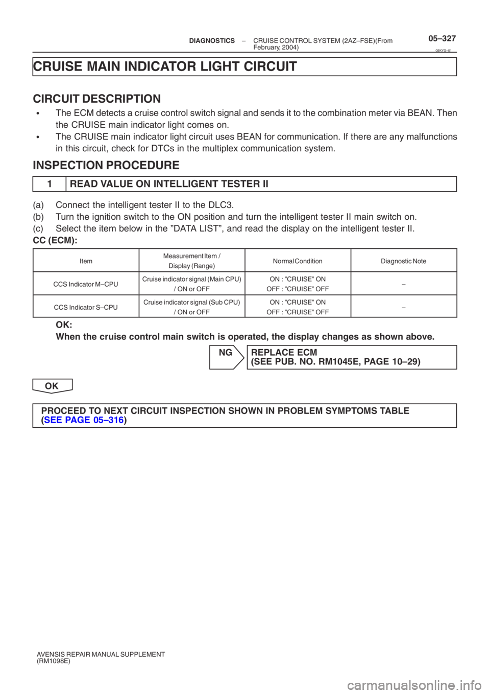
CC (ECM):
ItemMeasurement Item /
Display (Range)Normal ConditionDiagnostic Note
CCS Indicator M–CPUCruise indicator signal (Main CPU) / ON or OFFON : ”CRUISE” ON
OFF : ”CRUISE” OFF–
CCS Indicator S–CPUCruise indicator signal (Sub CPU) / ON or OFFON : ”CRUISE” ON
OFF : ”CRUISE” OFF–
OK:
When the cruise control main switch is operated, the display changes as show\
n above.
NG REPLACE ECM(SEE PUB. NO. RM1045E, PAGE 10–29)
OK
PROCEED TO NEXT CIRCUIT INSPECTION SHOWN IN PROBLEM SYMP TOMS TABLE
( SEE PAGE 05–316 )
05KYG–01
Page 5088 of 5135

056HK–07
05–316–
DIAGNOSTICS CRUISE CONTROL SYSTEM (2AZ–FSE)(From
February, 2004)
AVENSIS REPAIR MANUAL SUPPLEMENT
(RM1098E)
PROBLEM SYMPTOMS TABLE
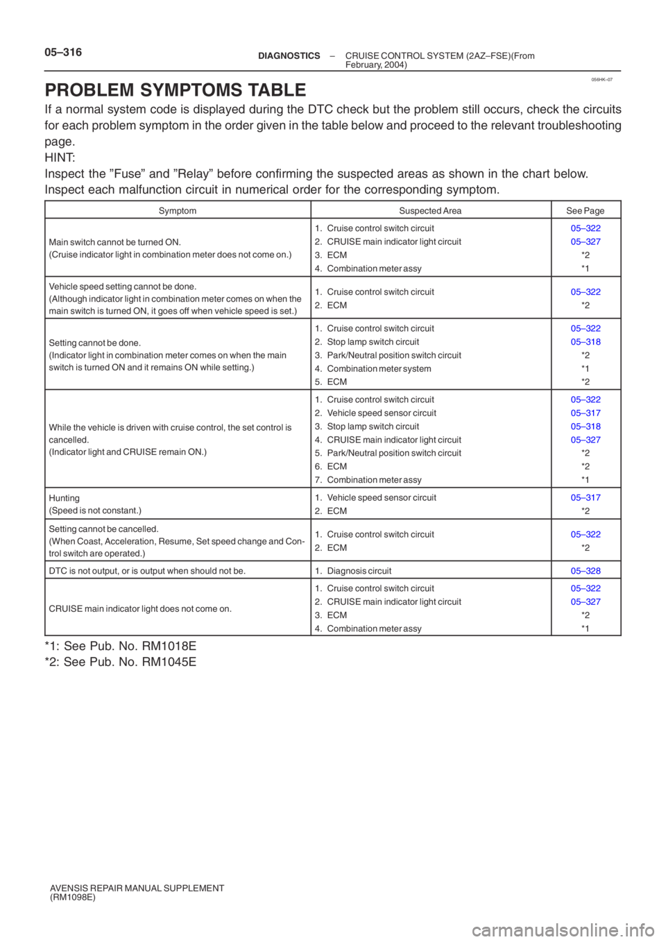
If a normal system code is displayed during the DTC check but the problem still occurs, check the circuits
for each problem symptom in the order given in the table below and proceed \
to the relevant troubleshooting
page.
HINT:
Inspect the ”Fuse” and ”Relay” before confirming the suspected area\
s as shown in the chart below.
Inspect each malfunction circuit in numerical order for the correspondin\
g symptom.
SymptomSuspected AreaSee Page
Main switch cannot be turned ON.
(Cruise indicator light in combination meter does not come on.)
1. Cruise control switch circuit
2. CRUISE main indicator light circuit
3. ECM
4. Combination meter assy05–322
05–327 *2
*1
Vehicle speed setting cannot be done.
(Although indicator light in combination meter comes on when the
main switch is turned ON, it goes off when vehicle speed is set.)1. Cruise control switch circuit
2. ECM05–322*2
Setting cannot be done.
(Indicator light in combination meter comes on when the main
switch is turned ON and it remains ON while setting.)
1. Cruise control switch circuit
2. Stop lamp switch circuit
3. Park/Neutral position switch circuit
4. Combination meter system
5. ECM05–322
05–318*2
*1
*2
While the vehicle is driven with cruise control, the set control is
cancelled.
(Indicator light and CRUISE remain ON.)
1. Cruise control switch circuit
2. Vehicle speed sensor circuit
3. Stop lamp switch circuit
4. CRUISE main indicator light circuit
5. Park/Neutral position switch circuit
6. ECM
7. Combination meter assy05–322
05–317
05–318
05–327*2
*2
*1
Hunting
(Speed is not constant.)1. Vehicle speed sensor circuit
2. ECM05–317
*2
Setting cannot be cancelled.
(When Coast, Acceleration, Resume, Set speed change and Con-
trol switch are operated.)1. Cruise control switch circuit
2. ECM05–322*2
DTC is not output, or is output when should not be.1. Diagnosis circuit05–328
CRUISE main indicator light does not come on.
1. Cruise control switch circuit
2. CRUISE main indicator light circuit
3. ECM
4. Combination meter assy05–322
05–327*2
*1
*1: See Pub. No. RM1018E
*2: See Pub. No. RM1045E
Page 5089 of 5135
05KYD–01
I33809
E13 E12 E11E10E9
– DIAGNOSTICSCRUISE CONTROL SYSTEM (2AZ–FSE)(From
February, 2004)05–315
AVENSIS REPAIR MANUAL SUPPLEMENT
(RM1098E)
TERMINALS OF ECM
Symbols (Terminals No.)Wiring ColorTerminal DescriptionConditionSpecified Condition
TC (E9–20) – E1 (E11–1)W–L – BRDTC input signalIgnition switch ON → Connect ter-
minals TC and CG of DLC310 to 14 V →
Below 2 V
ST1– (E10–12) – E1 (E11–1)G–W – BRCruise cancel input
signalIgnition switch ON, depress brake
pedal → release brake pedalBelow 1 V →
10 to 14 V
STP (E10–19) – E1 (E11–1)G–W – BRStop lamp switch
input signalIgnition switch ON, depress brake
pedal → release brake pedal10 to 14 V →
Below 1 V
CCS (E10–24) – E1 (E11–1)W – BRCruise control main
switch input signal
Ignition switch ON
Cancel switch held ON
SET/COAST switch held ON
RES/ACC switch held ON
MAIN switch held ON10 to 14 V
6.6 to 10.1 V
4.5 to 7.1 V
2.3 to 4 V
Below 1 V