Page 1755 of 5135
05±1720
± DIAGNOSTICSCRUISE CONTROL SYSTEM
AVENSIS REPAIR MANUAL (RM1018E)
INSPECTION PROCEDURE
HINT:
In case of using the hand±held tester, start the inspection from step 1, and in case of not using the hand±held
tester, start from step 2.
1 READ VALUE OF HAND±HELD TESTER
(a) Connect the hand±held tester to the DLC3.
(b) Turn the ignition switch to the ON position, and turn the hand±held tester main switch ON.
(c) Select the item ºCCS READYº in the DATA LIST and read its prompts displayed on the hand±held tes-
ter.
ItemMeasurement Item /
Display (Range)Normal ConditionDiagnostic Note
CCS READY MCruise control system standby
condition (Main CPU) / ON or OFFON ± OFF : Change ON/OFF
each time Main SW is pushed in.º1º
CCS READY SCruise control system standby
condition (Sub CPU) / ON or OFFON ± OFF : Change ON/OFF
each time Main SW is pushed in.º1º
NG Go to step 2
OK
PROCEED TO NEXT CIRCUIT INSPECTION SHOWN ON PROBLEM SYMPTOMS TABLE
Page 1756 of 5135

I35702
±
DIAGNOSTICS CRUISE CONTROL SYSTEM
05±1721
AVENSIS REPAIR MANUAL (RM1018E)
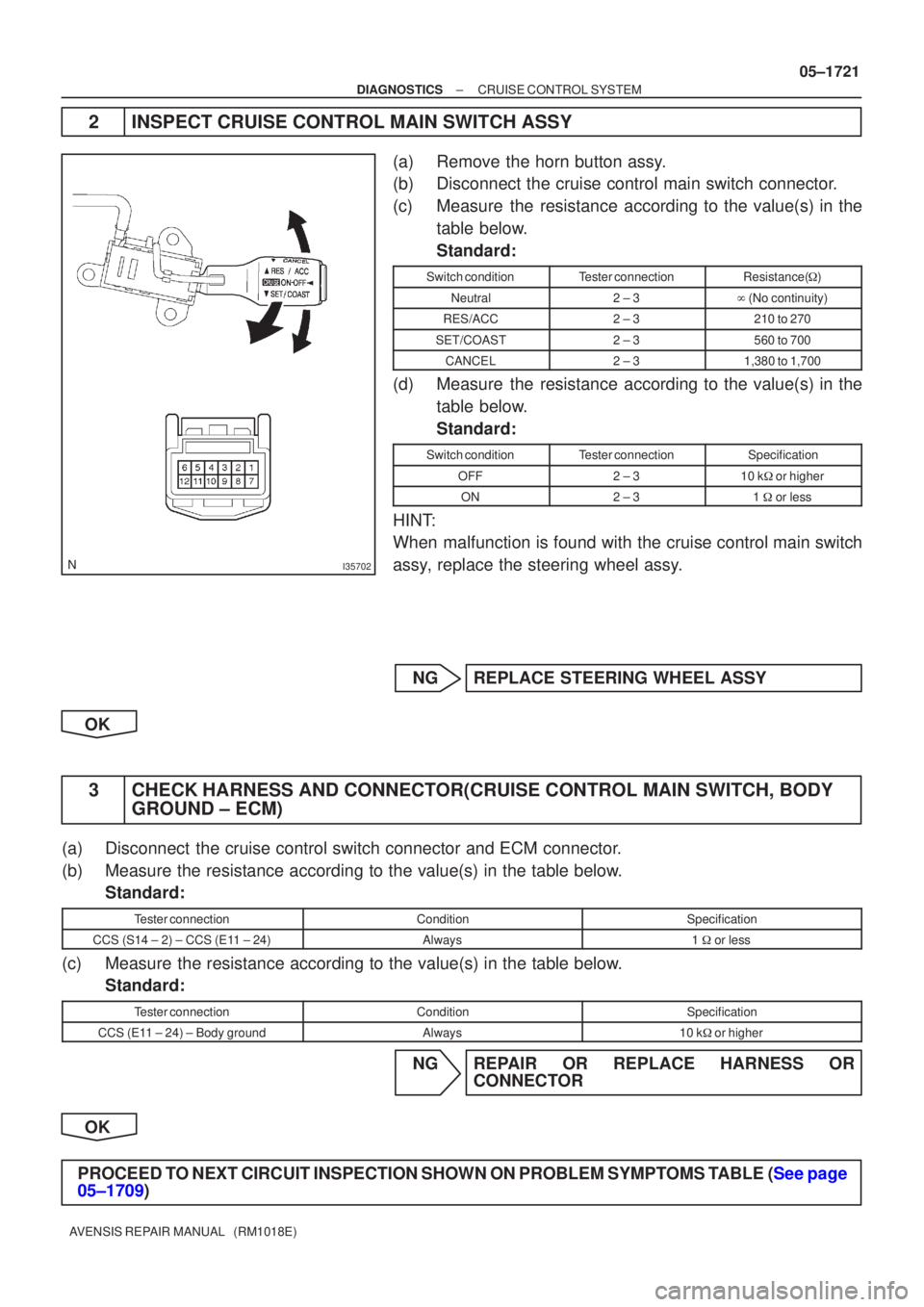
2INSPECT CRUISE CONTROL MAIN SWITCH ASSY
(a)Remove the horn button assy.
(b)Disconnect the cruise control main switch connector.
(c)Measure the resistance according to the value(s) in the
table below.
Standard:
Switch conditionTester connectionResistance( �)
Neutral2 ± 3� (No continuity)
RES/ACC2 ± 3210 to 270
SET/COAST2 ± 3560 to 700
CANCEL2 ± 31,380 to 1,700
(d)Measure the resistance according to the value(s) in the
table below.
Standard:
Switch conditionTester connectionSpecification
OFF2 ± 310 k� or higher
ON2 ± 31 � or less
HINT:
When malfunction is found with the cruise control main switch
assy, replace the steering wheel assy.
NGREPLACE STEERING WHEEL ASSY
OK
3CHECK HARNESS AND CONNECTOR(CRUISE CONTROL MAIN SWITCH, BODY GROUND ± ECM)
(a)Disconnect the cruise control switch connector and ECM connector.
(b)Measure the resistance according to the value(s) in the table below.
Standard:
Tester connectionConditionSpecification
CCS (S14 ± 2) ± CCS (E11 ± 24)Always1 � or less
(c)Measure the resistance according to the value(s) in the table below.
Standard:
Tester connectionConditionSpecification
CCS (E11 ± 24) ± Body groundAlways10 k� or higher
NGREPAIR OR REPLACE HARNESS OR
CONNECTOR
OK
PROCEED TO NEXT CIRCUIT INSPECTION SHOWN ON PROBLEM SYMPTOMS TABLE (See page
05±1709)
Page 1757 of 5135
±
DIAGNOSTICS CRUISE CONTROL SYSTEM
05±1717
AVENSIS REPAIR MANUAL (RM1018E)
DTC P0607/54 CONTROL MODULE PERFORMANCE
CIRCUIT DESCRIPTION
This DTC indicates the internal abnormalities of ECM.
DTC No.Detection ItemTrouble Area
P0607/54
The ECM has a supervisory CPU and control ECU inside.
When each input STP signal is different for 0.15 sec. or more,
the malfunction code is output.
The malfunction code is output after 0.4 sec. have passed from
the time the cruise cancel input signal (STP input) is input into
the ECM.
HINT:
�When a malfunction code is detected, the fail safe must be
kept on until the ignition switch is turned off.
�ECM
INSPECTION PROCEDURE
1REPLACE ECM (See page 01±32)
05C4S±01
Page 1758 of 5135

± DIAGNOSTICSCRUISE CONTROL SYSTEM
05±1711
AVENSIS REPAIR MANUAL (RM1018E)
DTC P0571/52 BRAKE SWITCH ºAº CIRCUIT
CIRCUIT DESCRIPTION
When the brake pedal is depressed, the stop lamp switch assy sends a signal to the ECM. When the ECM
receives this signal, it cancels the cruise control.
A fail±safe function is provided so that it functions normally, even if there is a malfunction in the stop lamp
signal circuit.
The cancel condition occurs when battery positive voltage is supplied to terminal STP.
When the brake is on, battery positive voltage is normally applied through the STOP fuse and the stop lamp
switch assy to terminal STP of the ECM, and the ECM turns the cruise control OFF.
If the harness connected to terminal STP has an open circuit, terminal STP will have battery positive voltage
and the cruise control will be turned OFF.
DTC No.DTC Detection ConditionTrouble Area
P0571/52
The malfunction code is output when the voltage of the STP
terminal and that of the ST1 terminal on the ECM are less than
1 V for 0.5 sec. or more.
When the following conditions are realized, a malfunction is
detected.
�The STP terminal voltage is less than 1 V.
�The ST1 terminal voltage is less than 1 V.
�For more than 0.5 sec. or more.
�Stop lamp switch assy
�Stop lamp switch assy circuit
�ECM
05C4R±01
Page 1759 of 5135
I35714
ECM
19
E11
STP
12
E11 ST1± R±WR±W
G±W
G±W(*1)
(*2)
(*1)
(*2) G±W
R±W
R±W
G±W
G±W(*1)
(*2)
(*1)
(*2) S13
Stop Lamp
Switch Assy
Engine Room R/B G±W
G±W G±W
G±W
B±W B±W
B±W B±W(*1) (*1)
(*2) (*2)
(*1)
(*1)
(*2) (*2)11
2
14
4 6
1
20
3IE3
IR1
IE2
IR1 IE3
IR1
IE1
IR1
4 312
I13
Ignition SW
B±R B±R
IG2 AM24
611
IE4 IP1
(*2) (*1)
B±R
1 1
1AAM2
12
Driver Side J/B Engine Room J/B No.4Driver Side J/B
ALT IGN
1
21
1 4A
4DB±G
1STOP
22
DN DA 1
4B B±G
FL MAIN
Battery2 18
DA DHDA DC10 2Driver Side J/B
J26 J8
J27 J9 AC ECJ/C
B±G (*2)(*2)
(*1)(*1)
*1: LHD
*2: RHD 1AZ±FSE
B±W 05±1712
± DIAGNOSTICSCRUISE CONTROL SYSTEM
AVENSIS REPAIR MANUAL (RM1018E)
WIRING DIAGRAM
Page 1760 of 5135
I35713
ECM
19
E11
STP
12
E11 ST1± R±WR±W
G±W
G±W(*1)
(*2)
(*1)
(*2) G±W
R±W
R±W
G±W
G±W(*1)
(*2)
(*1)
(*2) S13
Stop Lamp
Switch Assy
Engine Room R/B G±W
G±W G±W
G±W
B±W B±W
B±W B±W(*1) (*1)
(*2) (*2)
(*1)
(*1)
(*2) (*2)11
2
14
4 6
1
20
3IE3
IR1
IE2
IR1 IE3
IR1
IE1
IR1
4 312
I13
Ignition SW
B±R B±R
IG2 AM24
611
IE4 IP1
(*2) (*1)
B±R
1 1
1AAM2
12
Driver Side J/B Engine Room J/B No.4Driver Side J/B
ALTIGN
1
2 3B
1STOP
22
DN DA B
FL MAIN
Battery2 18
DA DHDA DC10 2Driver Side J/B
J26 J8
J27 J9 AC ECJ/C
B±L (*2)(*2)
(*1)(*1)
*1: LHD
*2: RHD 1CD±FTV
3
3W
1
ED1 B±W
± DIAGNOSTICSCRUISE CONTROL SYSTEM
05±1713
AVENSIS REPAIR MANUAL (RM1018E)
Page 1761 of 5135

05±1714
± DIAGNOSTICSCRUISE CONTROL SYSTEM
AVENSIS REPAIR MANUAL (RM1018E)
INSPECTION PROCEDURE
HINT:
In case of using the hand±held tester, start the inspection from step1, and in case of not using the hand±held
tester, start from step 2.
1 READ VALUE OF HAND±HELD TESTER
(a) Connect the hand±held tester to the DLC3.
(b) Turn the ignition switch to the ON position and turn the hand±held tester main switch ON.
(c) Select the item ºSTOP LIGHT SWº in the DATA LIST and read the displayed value.
ItemMeasurement Item /
Display (Range)Normal ConditionDiagnostic Note
STP LIGHT SW2 MStop lamp SW signal (Main CPU) /
ON or OFFON : Brake pedal depressed
OFF : Brake pedal released±
STP LIGHT SW2 SStop lamp SW signal (Sub CPU) /
ON or OFFON : Brake pedal depressed
OFF : Brake pedal released±
Standard:
Brake pedal depressed: OK
Brake pedal released: OFF
NG Go to step 2
OK
PROCEED TO NEXT CIRCUIT INSPECTION SHOWN ON PROBLEM SYMPTOMS TABLE
2 INSPECT STOP LAMP SWITCH OPERATION
(a) Check that the stop lamp lights up when brake pedal is depressed, and goes off when the brake pedal
is released.
NG INSPECT STOP LAMP SWITCH CIRCUIT
OK
Page 1762 of 5135
E67360
Free2Pushed in1
43
I35703
1AZ±FSE:
STP
STP
1CD±FTV:
± DIAGNOSTICSCRUISE CONTROL SYSTEM
05±1715
AVENSIS REPAIR MANUAL (RM1018E)
3 INSPECT STOP LAMP SWITCH ASSY
(a) Disconnect the stop lamp switch assy connector.
(b) Measure the resistance according to the value(s) in the
table below.
Standard:
Switch conditionTester connectionSpecification
Switch pin free1 ± 21 � or less
Switch pin free3 ± 410 k� or higher
Switch pin pushed in1 ± 210 k� or higher
Switch pin pushed in3 ± 41 � or less
NG REPLACE STOP LAMP SWITCH ASSY
OK
4 INSPECT ECM
(a) Remove the ECM with connectors.
(b) Turn the ignition switch to the ON position.
(c) Measure the voltage between terminal STP of ECM con-
nector and body ground when the brake pedal is de-
pressed and released.
Standard:
Pedal conditionTester connectionSpecification
DepressedSTP (E11±19) ± Body
ground10 to 14 V
ReleasedSTP (E11±19) ± Body
ground1 V or less