Page 630 of 5135

3 2 1 45678
9 1 0 111 21 31 41 51 6
DLC3
A04550
± DIAGNOSTICSECD SYSTEM (1CD±FTV)
05±529
AVENSIS REPAIR MANUAL (RM1018E)
�* 2 trip detection logic
When a logic malfunction is first detected, the pend-
ing fault code is stored in the ECM memory (1st trip).
If the same malfunction is detected again during the
second drive test, this second detection causes the
CHK ENG to illuminate (2nd trip) (However, the igni-
tion switch must be turned OFF between the 1st trip
and 2nd trip).
�Freeze frame data:
The freeze frame data records the engine condi-
tions (fuel system, calculator load, engine coolant
temperature, engine speed, vehicle speed, etc.)
when the malfunction is detected. When trouble-
shooting, it is useful for determining whether the ve-
hicle was running or stopped, the engine was
warmed up or not, etc. at the time of the malfunc-
tion.
�Priorities for troubleshooting:
If troubleshooting priorities for multiple DTCs are
given in the applicable DTC chart, these should be
followed.
(b) Check the DLC3.
The vehicle's ECM uses the ISO 9141±2(Euro±OBD)
communication protocol. The terminal arrangement of
the DLC3 complies with ISO 15031±03 and matches the
ISO 9141±2 format.
Terminal No.Connection / Voltage or ResidenceCondition
7Bus + Line / Pulse generation+During transmission
4Chassis Ground ± Body Ground / 1 � or lessAlways
16Battery Positive ± Body Ground / 9 to 14 VAlways
HINT:
If the display shows ºUNABLE TO CONNECT TO VEHICLEº
when you have connected the cable of the hand±held tester to
the DLC3, turned the ignition switch ON and operated the
hand±held tester, there is a problem on the vehicle side or tool
side.
�If communication is normal when the tool is connected to
another vehicle, inspect the DLC3 on the original vehicle.
�If communication is still impossible when the tool is con-
nected to another vehicle, the problem is probably in the
tool itself, so consult the Service Deparment listed in the
tool's instruction manual.
Page 631 of 5135

A76859
Hand±held
Tester
DLC3
05±530
±
DIAGNOSTICS ECD SYSTEM(1CD±FTV)
AVENSIS REPAIR MANUAL (RM1018E)
(c)Inspect the battery voltage. Battery voltage: 11 to 14 V
If voltage is below 11V, recharge the battery before proceeding.
(d)Check the CHK ENG.
(1)The CHK ENG lamp comes on when the ignitionswitch is turned ON and the engine is not running.
HINT:
If the CHK ENG is not illuminate, troubleshoot the combination
meter.
(2)When the engine is started, the CHK ENG shouldgo off. If the lamp remains on, it means that the diag-
nosis system has detected a malfunction or ab-
normality in the system.
2.DTC CHECK (Normal Mode):
NOTICE:
Hand±held tester only:
When the diagnosis system is switched from the normal
mode to the check mode, it erases all DTCs and freeze
frame data recorded in the normal mode. So before switch-
ing modes, always check the DTCs and freeze frame data,
and then write them down.
(a)Checking DTCs using the hand±held tester. (1)Connect the hand±held tester to the DLC3.
(2)Turn the ignition switch ON and switch the hand±held tester main switch ON.
(3)Use the hand±held tester to check the DTCs and freeze frame data and then write them down. If you
need help with the hand±held tester, refer to the
hand±held tester's instruction book).
(4)See page 05±544 to confirm the details of the
DTCs.
(b) Clearing the DTCs using the hand±held tester: (1) Connect the hand±held tester to the DLC3.
(2) Turn the ignition switch ON.
(3) When operating the hand±held tester to erase thecodes, the DTCs and freeze frame data will be
erased. (See the hand±held tester's instruction
book for operating instructions.)
(c) Clearing the DTCs not using the hand±held tester:
(1) Disconnect the battery terminal or remove the EFIand ETCS fuses from the engine room R/B for more
than 60 seconds.
Page 632 of 5135

A76900
ON
OFF
0.13 Sec0.13 Sec
± DIAGNOSTICSECD SYSTEM (1CD±FTV)
05±531
AVENSIS REPAIR MANUAL (RM1018E)
3. DTC CHECK (Check Mode):
HINT:
Hand±held tester only:
Compared to the normal mode, the check mode has more sens-
ing ability to detect malfunctions. Furthermore, the same diag-
nostic items which are detected in the normal mode can also be
detected in the check mode.
(a) Procedure for Check Mode using the hand±held tester.
(1) Check the initial conditions.
�Battery positive voltage 11V or more.
�Throttle valve fully closed.
�Transmission in the ºNº position.
�A/C switched OFF.
(2) Turn the ignition switch OFF.
(3) Connect the hand±held tester to the DLC3.
(4) Turn the ignition switch ON and switch the hand±
held tester main switch ON.
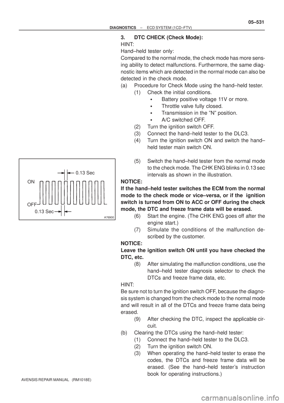
(5) Switch the hand±held tester from the normal mode
to the check mode. The CHK ENG blinks in 0.13 sec
intervals as shown in the illustration.
NOTICE:
If the hand±held tester switches the ECM from the normal
mode to the check mode or vice±versa, or if the ignition
switch is turned from ON to ACC or OFF during the check
mode, the DTC and freeze frame data will be erased.
(6) Start the engine. (The CHK ENG goes off after the
engine start.)
(7) Simulate the conditions of the malfunction de-
scribed by the customer.
NOTICE:
Leave the ignition switch ON until you have checked the
DTC, etc.
(8) After simulating the malfunction conditions, use the
hand±held tester diagnosis selector to check the
DTCs and freeze frame data, etc.
HINT:
Be sure not to turn the ignition switch OFF, because the diagno-
sis system is changed from the check mode to the normal mode
and will result in all of the DTCs and freeze frame data being
erased.
(9) After checking the DTC, inspect the applicable cir-
cuit.
(b) Clearing the DTCs using the hand±held tester:
(1) Connect the hand±held tester to the DLC3.
(2) Turn the ignition switch ON.
(3) When operating the hand±held tester to erase the
codes, the DTCs and freeze frame data will be
erased. (See the hand±held tester's instruction
book for operating instructions.)
Page 633 of 5135

05±532
± DIAGNOSTICSECD SYSTEM (1CD±FTV)
AVENSIS REPAIR MANUAL (RM1018E)
(c) Clearing the DTCs not using the hand±held tester:
(1) Disconnect the battery terminal or remove the EFI
and ETCS fuses from the engine room R/B for more
than 60 seconds.
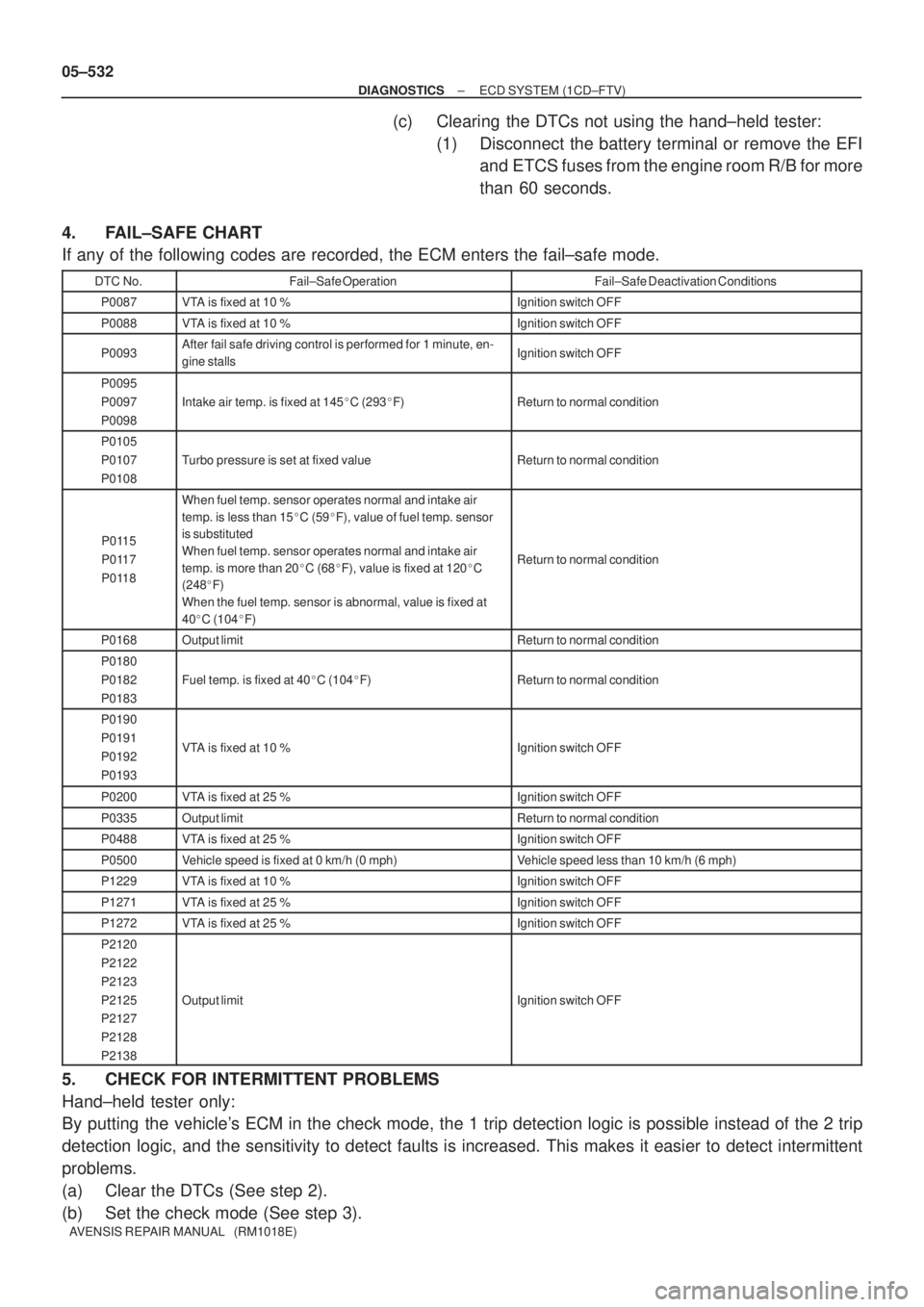
4. FAIL±SAFE CHART
If any of the following codes are recorded, the ECM enters the fail±safe mode.
DTC No.Fail±Safe OperationFail±Safe Deactivation Conditions
P0087VTA is fixed at 10 %Ignition switch OFF
P0088VTA is fixed at 10 %Ignition switch OFF
P0093After fail safe driving control is performed for 1 minute, en-
gine stallsIgnition switch OFF
P0095
P0097
P0098
Intake air temp. is fixed at 145�C (293�F)Return to normal condition
P0105
P0107
P0108
Turbo pressure is set at fixed valueReturn to normal condition
P0115
P0117
P0118
When fuel temp. sensor operates normal and intake air
temp. is less than 15�C (59�F), value of fuel temp. sensor
is substituted
When fuel temp. sensor operates normal and intake air
temp. is more than 20�C (68�F), value is fixed at 120�C
(248�F)
When the fuel temp. sensor is abnormal, value is fixed at
40�C (104�F)
Return to normal condition
P0168Output limitReturn to normal condition
P0180
P0182
P0183
Fuel temp. is fixed at 40�C (104�F)Return to normal condition
P0190
P0191
P0192
P0193
VTA is fixed at 10 %Ignition switch OFF
P0200VTA is fixed at 25 %Ignition switch OFF
P0335Output limitReturn to normal condition
P0488VTA is fixed at 25 %Ignition switch OFF
P0500Vehicle speed is fixed at 0 km/h (0 mph)Vehicle speed less than 10 km/h (6 mph)
P1229VTA is fixed at 10 %Ignition switch OFF
P1271VTA is fixed at 25 %Ignition switch OFF
P1272VTA is fixed at 25 %Ignition switch OFF
P2120
P2122
P2123
P2125
P2127
P2128
P2138
Output limitIgnition switch OFF
5. CHECK FOR INTERMITTENT PROBLEMS
Hand±held tester only:
By putting the vehicle's ECM in the check mode, the 1 trip detection logic is possible instead of the 2 trip
detection logic, and the sensitivity to detect faults is increased. This makes it easier to detect intermittent
problems.
(a) Clear the DTCs (See step 2).
(b) Set the check mode (See step 3).
Page 637 of 5135
Are you read the injector
A81230
Reading flowchart: 05±536
± DIAGNOSTICSECD SYSTEM (1CD±FTV)
AVENSIS REPAIR MANUAL (RM1018E)
8. READ INJECTOR COMPENSATION CODE
HINT:
This operation is useful when confirming the compensation
code of each injector or when DTC P1601 is present.
(a) Connect the hand±held tester to the DLC 3.
(b) Turn the ignition switch ON.
(c) Turn the main switch of the hand±held tester ON.
NOTICE:
Do not start the engine in this operation.
Page 638 of 5135
A80985
A66061
A66063
A66064
A66065
± DIAGNOSTICSECD SYSTEM (1CD±FTV)
05±537
AVENSIS REPAIR MANUAL (RM1018E)
(d) Enter ºDIAGNOSIS / OBD/MOBD / DIAGNOSTIC MENU
ECDº and select the item ºINJECTOR COMP.º
(e) Press the ºENTERº button on the hand±held tester.
(f) Press the ºENTERº button again.
(g) Select ºREAD COMP VALUEº and press the ºENTERº
button.
(h) Select a cylinder number which you want to read the com-
pensation code.
(i) Press the ºENTERº button.
(j) Wait until the next screen comes up.
Page 639 of 5135
A66066
A66067
05±538
± DIAGNOSTICSECD SYSTEM (1CD±FTV)
AVENSIS REPAIR MANUAL (RM1018E)
(k) Confirm the 30±digit±alphanumeric code which is dis-
played on the hand±held tester. This is the injection com-
pensation code for the cylinder.
HINT:
The code shown in the illustration is an example.
(l) Press the ºENTERº button to exit this screen.
(m) Press the ºNOº button to complete the confirmation.
HINT:
�If you want to read other compensation codes for other
cylinders, press the ºYESº button instead of ºNO.º
�By pressing the ºNOº button, the hand±held tester returns
to the ºDIAGNOSTIC MENU ECDº screen.
Page 640 of 5135
Register the injector compensation code
(Set the injector compensation code)other cylinders?Register the injector compensation code
(Set the injector compensation code)other cylinders?
A81231
Setting flowchart:
± DIAGNOSTICSECD SYSTEM (1CD±FTV)
05±539
AVENSIS REPAIR MANUAL (RM1018E)
9. SET INJECTOR COMPENSATION CODE
HINT:
This operation must be done when replacing the ECM or the in-
jectors.
(a) Connect the hand±held tester to the DLC 3.
(b) Turn the ignition switch ON.
(c) Turn the main switch of the hand±held tester ON.
NOTICE:
Do not start the engine in this operation.