Page 441 of 5135

05CDT±01
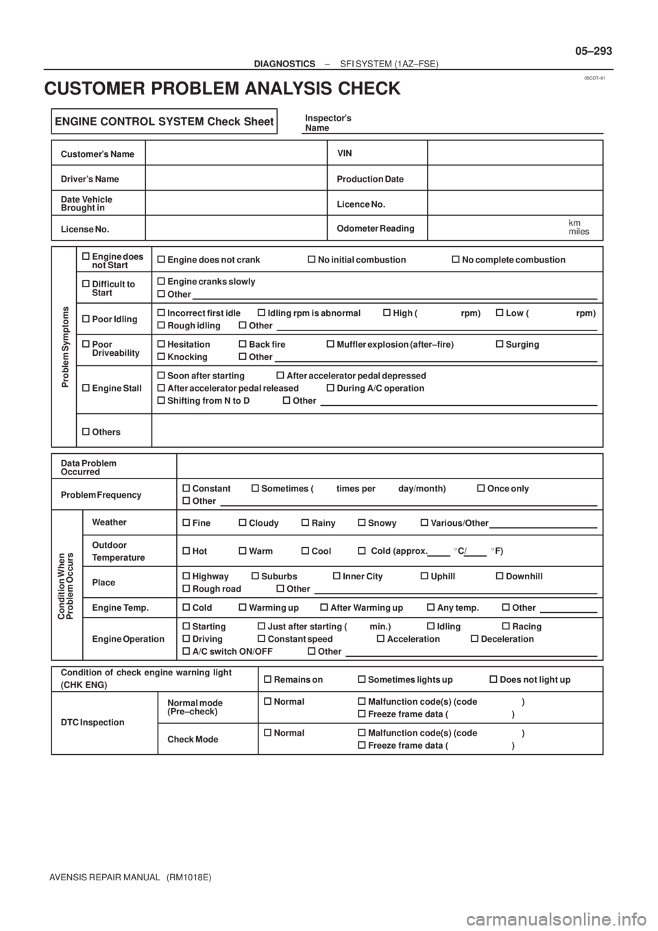
ENGINE CONTROL SYSTEM Check Sheet
Customer's Name
Driver's Name
Date Vehicle
Brought in
License No.
VIN
Production Date
Licence No.
Odometer Reading
km
miles
Problem Symptoms
Engine does
not Start
Difficult to
Start
Poor Idling
Poor
Driveability
Engine Stall
Others
Engine does not crankNo initial combustionNo complete combustion
Engine cranks slowly
Other
Incorrect first idleIdling rpm is abnormalHigh ( rpm)Low ( rpm)
Rough idling
Other
HesitationBack fireMuffler explosion (after±fire)Surging
Knocking
Other
Soon after startingAfter accelerator pedal depressed
After accelerator pedal released
During A/C operation
Shifting from N to D
Other
Data Problem
Occurred
Problem Frequency
Condition When
Problem Occurs
Weather
Engine Operation
Engine Temp. Place Outdoor
TemperatureConstant
Sometimes ( times per day/month)Once only
Other
Fine
CloudyRainySnowyVarious/Other
Hot
Warm Cool
HighwaySuburbsInner CityUphillDownhill
Rough road
Other
Cold
Warming upAfter Warming upAny temp.Other
Starting
Just after starting ( min.)IdlingRacing
Driving
Constant speedAccelerationDeceleration
A/C switch ON/OFF
Other
Condition of check engine warning light
(CHK ENG)Remains on Sometimes lights up Does not light up
Normal Malfunction code(s) (code )
Freeze frame data ( )
Normal Malfunction code(s) (code )
Freeze frame data ( )
Normal mode
(Pre±check)
Check Mode DTC InspectionInspector's
Name
Cold (approx. �C/ �F)
± DIAGNOSTICSSFI SYSTEM (1AZ±FSE)
05±293
AVENSIS REPAIR MANUAL (RM1018E)
CUSTOMER PROBLEM ANALYSIS CHECK
Page 443 of 5135
±
DIAGNOSTICS SFI SYSTEM(1AZ±FSE)
05±291
AVENSIS REPAIR MANUAL (RM1018E)
9SYMPTOM SIMULATION
10DTC CHECK (See page 05±294)
AMalfunction code
BNo code
B GO TO STEP 12
A
11DTC CHART (See page 05±309)
GO TO STEP 14
12BASIC INSPECTION (See page 05±294)
AWrong parts not confirmed
BWrong parts confirmed
B GO TO STEP 17
A
13PROBLEM SYMPTOMS TABLE (See page 05±320)
AWrong circuit confirmed
BWrong parts confirmed
B GO TO STEP 17
A
14CHECK ECM POWER SOURCE CIRCUIT (See page 05±502)
15 CIRCUIT INSPECTION
AMalfunction not confirmed
BMalfunction confirmed
B GO TO STEP 18
A
Page 452 of 5135

A65748
E9
ECM Connector
±
DIAGNOSTICS SFI SYSTEM(1AZ±FE)
05±283
AVENSIS REPAIR MANUAL (RM1018E)
1CLEAR DTC
(a)Connect the hand±held tester to the DLC 3.
(b)Turn the ignition switch ON and push the hand±held tester main switch \
ON.
(c)Read the DTC (See page 05±149).
(d)Clear the DTC (See page 05±149).
(e)Check that the CHK ENG is OFF.
Standard: CHK ENG is OFF
OKREPAIR CIRCUIT INDICATED BY OUTPUTCODE (See page 05±161)
NG
2CHECK HARNESS AND CONNECTOR(CHECK FOR SHORT IN WIRE HARNESS)
(a)Disconnect the E9 ECM connector.
(b)Turn the ignition switch ON.
(c)Check that the CHK ENG is OFF. Standard: CHK ENG is OFF
OKCHECK AND REPLACE ECM (See page 01±32)
NG
CHECK AND REPAIR HARNESS AND CONNECTOR
3CHECK CHK ENG CONDITION
(a)Check that the CHK ENG is illuminated when turning the ignition switch O\
N. Standard: CHK ENG is illuminated
OKCHECK AND REPAIR HARNESS ANDCONNECTOR
NG
4INSPECT COMBINATION METER ASSY(CHK ENG CIRCUIT)
(a)See the combination meter troubleshooting on page 05±1509. NG REPAIR OR REPLACE BULB OR COMBINATIONMETER ASSEMBLYSYSTEM OK
OK
CHECK AND REPAIR HARNESS AND CONNECTOR
Page 470 of 5135

±
DIAGNOSTICS SFI SYSTEM(1AZ±FSE)
05±355
AVENSIS REPAIR MANUAL (RM1018E)
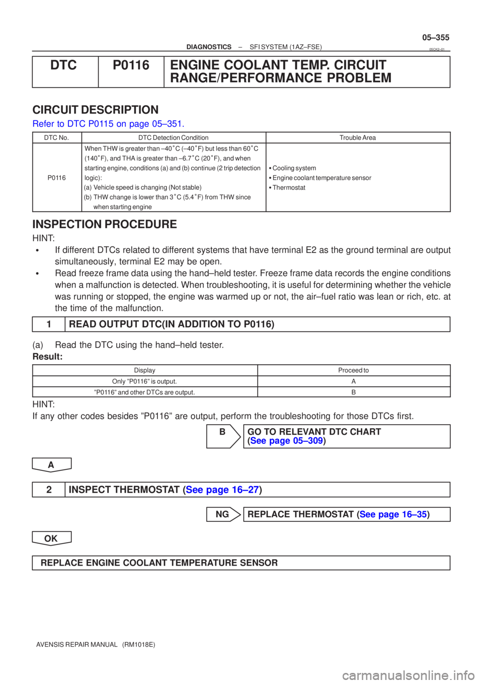
DTCP0116ENGINE COOLANT TEMP. CIRCUIT
RANGE/PERFORMANCE PROBLEM
CIRCUIT DESCRIPTION
Refer to DTC P0115 on page 05±351.
DTC No.DTC Detection ConditionTrouble Area
P0116
When THW is greater than ±40 �C (±40 �F) but less than 60 �C
(140 �F), and THA is greater than ±6.7 �C (20 �F), and when
starting engine, conditions (a) and (b) continue (2 trip detection
logic):
(a)Vehicle speed is changing (Not stable)
(b)THW change is lower than 3 �C (5.4 �F) from THW since
when starting engine
� Cooling system
� Engine coolant temperature sensor
� Thermostat
INSPECTION PROCEDURE
HINT:
�If different DTCs related to different systems that have terminal E2 as the ground terminal are output
simultaneously, terminal E2 may be open.
�Read freeze frame data using the hand±held tester. Freeze frame data records the engine conditions
when a malfunction is detected. When troubleshooting, it is useful for deter\
mining whether the vehicle
was running or stopped, the engine was warmed up or not, the air±fuel ra\
tio was lean or rich, etc. at
the time of the malfunction.
1READ OUTPUT DTC(IN ADDITION TO P0116)
(a)Read the DTC using the hand±held tester.
Result:
DisplayProceed to
Only ºP0116º is output.A
ºP0116º and other DTCs are output.B
HINT:
If any other codes besides ºP0116º are output, perform the troubleshooting for those DTCs first.
BGO TO RELEVANT DTC CHART (See page 05±309)
A
2INSPECT THERMOSTAT (See page 16±27)
NGREPLACE THERMOSTAT (See page 16±35)
OK
REPLACE ENGINE COOLANT TEMPERATURE SENSOR
05CK2±01
Page 498 of 5135

05±326
± DIAGNOSTICSSFI SYSTEM (1AZ±FSE)
AVENSIS REPAIR MANUAL (RM1018E)
2 PERFORM ACTIVE TEST BY HAND±HELD TESTER(OPERATE OCV)
(a) Connect the hand±held tester to the DLC3.
(b) Start the engine and warm it up.
(c) Turn the ignition switch ON and push the hand±held tester main switch ON.
(d) Select the item ºDIAGNOSIS / OBD/MOBD / ACTIVE TEST / VVT CTRL B1º.
(e) Check the engine speed when operating the OCV by the hand±held tester.
Standard:
Tester operationSpecified condition
OCV is OFFNormal engine speed
OCV is ONRough idle or engine stall
NG Go to step 4
OK
3 CHECK IF DTC OUTPUTS REOCCUR
(a) Clear the DTC.
(1) Operating the hand±held tester to erase the codes, or disconnecting the battery terminal or the
EFI and ETCS fuses for 60 seconds or more.
(b) Start the engine and warm it up.
(c) Drive the vehicle around for 10 minutes or more.
(d) Read output DTC using the hand±held tester.
Standard: No DTC output.
HINT:
*: DTCs P0011 or P0012 is output when a foreign object in engine oil is caught in some part of the system.
These codes will stay registered even if the system returns to normal after a short time. These foreign objects
are then captured by the oil filter, thus eliminating the source of the problem.
OK VVT SYSTEM OK *
NG
Page 500 of 5135
05±328
±
DIAGNOSTICS SFI SYSTEM(1AZ±FSE)
AVENSIS REPAIR MANUAL (RM1018E)
9REPLACE CAMSHAFT TIMING GEAR ASSY (See page 14±240)
GO
10CHECK BLOCKAGE(OCV, OIL CHECK VALVE AND OIL HOLE)
NGREPAIR OR REPLACE
OK
11CHECK IF DTC OUTPUTS REOCCUR
(a)Clear the DTC. (1)Operating the hand±held tester to erase the codes, or disconnecting the batter\
y terminal or the
EFI and ETCS fuses for 60 seconds or more.
(b)Start the engine and warm it up.
(c)Drive the vehicle around for 10 minutes or more.
(d)Read output DTC using the hand±held tester.
Standard: No DTC output.
HINT:
*: DTCs P0011 or P0012 is output when a foreign object in engine oil is caught in so\
me part of the system.
These codes will stay registered even if the system returns to normal after a\
short time. These foreign objects
are then captured by the oil filter, thus eliminating the source of the problem.
OKVVT SYSTEM OK
NG
CHECK AND REPLACE ECM (See page 01±32)
Page 521 of 5135

±
DIAGNOSTICS SFI SYSTEM(1AZ±FSE)
05±411
AVENSIS REPAIR MANUAL (RM1018E)
WIRING DIAGRAM
Refer to DTC P1235 on page 05±477.
INSPECTION PROCEDURE
HINT:
�If different DTCs related to different systems that have terminal E2 as the ground terminal are output
simultaneously, terminal E2 may be open.
�Read freeze frame data using the hand±held tester. Freeze frame data records the engine conditions
when a malfunction is detected. When troubleshooting, it is useful for deter\
mining whether the vehicle
was running or stopped, the engine was warmed up or not, the air±fuel ra\
tio was lean or rich, etc. at
the time of the malfunction.
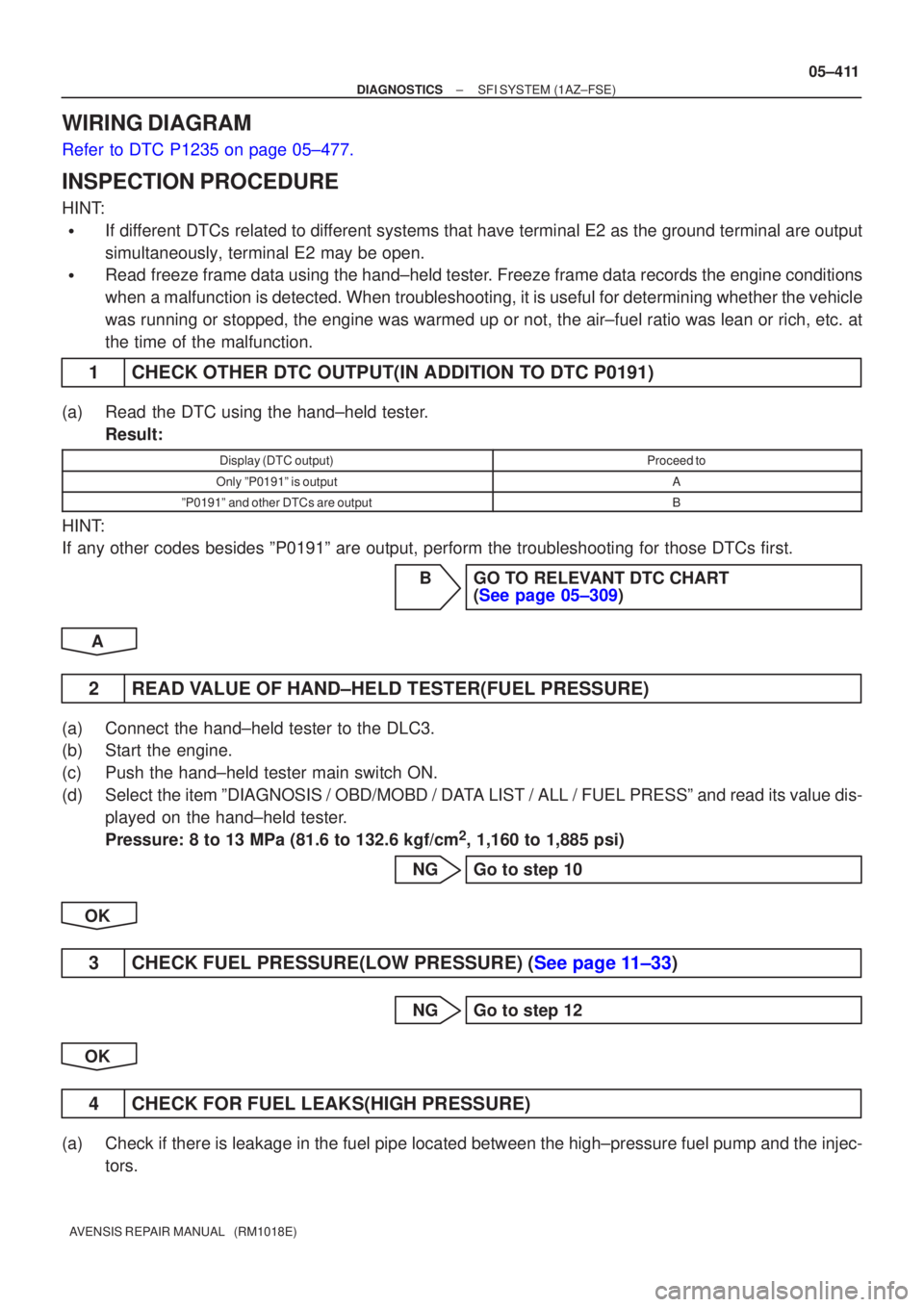
1CHECK OTHER DTC OUTPUT(IN ADDITION TO DTC P0191)
(a)Read the DTC using the hand±held tester.
Result:
Display (DTC output)Proceed to
Only ºP0191º is outputA
ºP0191º and other DTCs are outputB
HINT:
If any other codes besides ºP0191º are output, perform the troublesh\
ooting for those DTCs first.
BGO TO RELEVANT DTC CHART(See page 05±309)
A
2READ VALUE OF HAND±HELD TESTER(FUEL PRESSURE)
(a)Connect the hand±held tester to the DLC3.
(b)Start the engine.
(c)Push the hand±held tester main switch ON.
(d)Select the item ºDIAGNOSIS / OBD/MOBD / DATA LIST / ALL / FUEL PRESSº and read its value dis- played on the hand±held tester.
Pressure: 8 to 13 MPa (81.6 to 132.6 kgf/cm
2, 1,160 to 1,885 psi)
NGGo to step 10
OK
3CHECK FUEL PRESSURE(LOW PRESSURE) (See page 11±33)
NG Go to step 12
OK
4 CHECK FOR FUEL LEAKS(HIGH PRESSURE)
(a) Check if there is leakage in the fuel pipe located between the high±pressure fuel pump and the injec- tors.
Page 532 of 5135
±
DIAGNOSTICS SFI SYSTEM(1AZ±FSE)
05±397
AVENSIS REPAIR MANUAL (RM1018E)
1CHECK OTHER DTC OUTPUT(IN ADDITION TO DTC P0171, P0172, P0174
AND/OR P0175)
(a)Read the DTC using the hand±held tester.
Result:
Display (DTC output)Proceed to
Only ºP0171, P0172, P0174 and/or P0175º are outputA
ºP0171, P0172, P0174 or P0175º and other DTCs are outputB
HINT:
�If any other codes besides ºP0171, P0172, P0174 and/or P0175º are output, perform the troubleshoot-
ing for those DTCs first.
�If a misfiring DTC(s) is present, record the DTC(s) that indicates mis\
firing cylinder(s), then proceed to
A.
BGO TO RELEVANT DTC CHART (See page 05±309)
A
2 CHECK AIR INDUCTION SYSTEM
(a) Check for vacuum leaks in air the induction system. NG REPAIR OR REPLACE AIR INDUCTION SYSTEM
OK
3 CHECK CONNECTION OF PCV HOSE
NG REPAIR OR REPLACE PCV HOSE
OK