Page 641 of 5135
A80985
A66061
A66062
A66068
A66069
05±540
± DIAGNOSTICSECD SYSTEM (1CD±FTV)
AVENSIS REPAIR MANUAL (RM1018E)
(d) Enter ºDIAGNOSIS / OBD/MOBD / DIAGNOSTIC MENU
ECDº and select the item ºINJECTOR COMP.º
(e) Press the ºENTERº button on the hand±held tester.
(f) Press the ºEnterº button again.
(g) Select ºSET COMP VALUEº and press the ºENTERº but-
ton.
(h) Press the ºENTERº button.
(i) Select a cylinder number which you want to register the
compensation code.
(j) Press the ºENTERº button.
Page 642 of 5135

A66070
A66071
A66072
A66073
± DIAGNOSTICSECD SYSTEM (1CD±FTV)
05±541
AVENSIS REPAIR MANUAL (RM1018E)
(k) Input the 30±digit±alphanumeric code with the hand±
held tester to register the compensation code to the ECM.
NOTICE:
Be careful not to register a wrong compensation code to
the ECM. The compensation code which stored in the ECM
must be consistent with the compensation code of the in-
jector assembly. If a wrong code was set to the ECM, rough
idling or engine rattling may result. In addition, it may be a
cause of the engine failure or short±life.
(l) After inputting, press the ºENTERº button.
(m) Press the ºENTERº button again.
(n) Confirm the injection compensation code which is dis-
played on the hand±held tester.
HINT:
The code shown in the illustration is an example.
NOTICE:
�Make sure the correct compensation code is entered
on the hand±held tester before pressing YES button.
�If a wrong compensation code was entered on the
hand±held tester, select the ºNOº button to correct
the error (Back to step (g)).
(o) Press the ºYESº button to set the code to the ECM.
(p) Wait until the next screen comes up.
Page 643 of 5135

A66074
A66289
Inside
05±542
±
DIAGNOSTICS ECD SYSTEM(1CD±FTV)
AVENSIS REPAIR MANUAL (RM1018E)
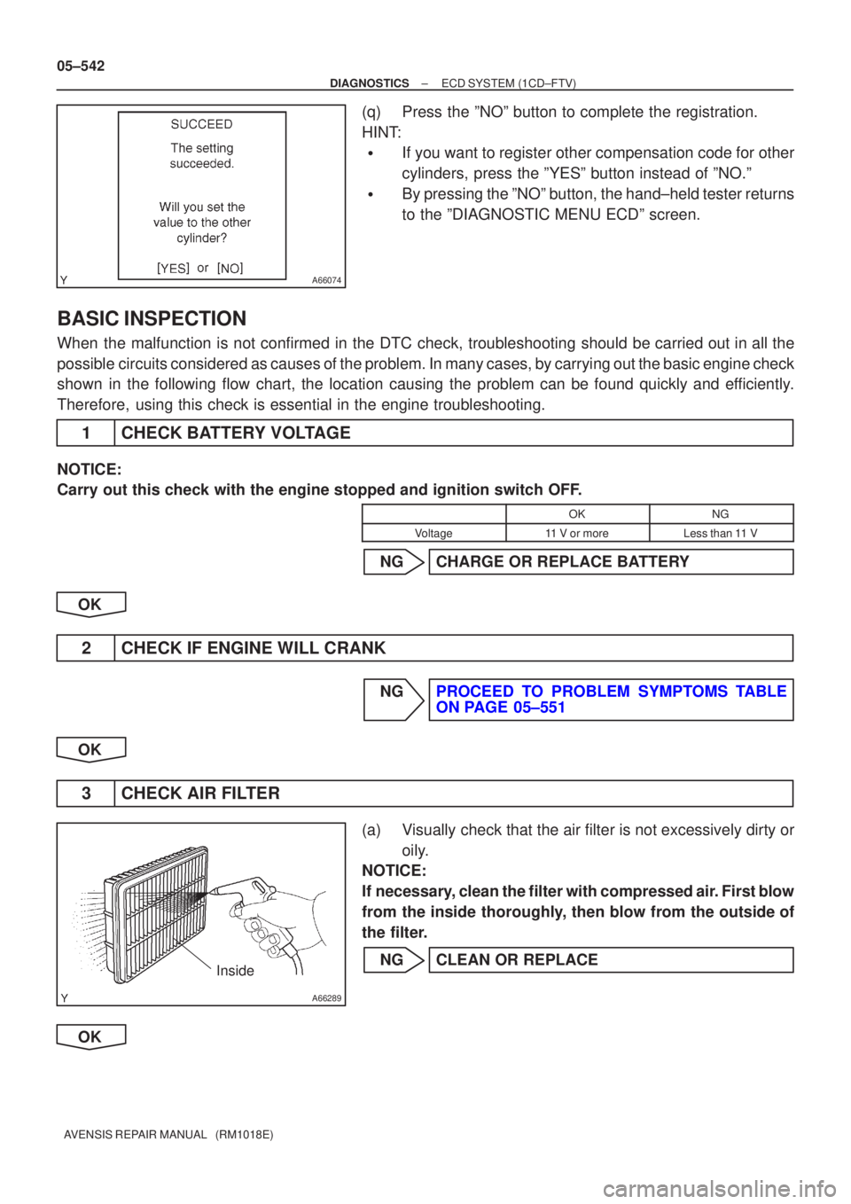
(q)Press the ºNOº button to complete the registration.
HINT:
�If you want to register other compensation code for other
cylinders, press the ºYESº button instead of ºNO.º
�By pressing the ºNOº button, the hand±held tester returns
to the ºDIAGNOSTIC MENU ECDº screen.
BASIC INSPECTION
When the malfunction is not confirmed in the DTC check, troubleshooting shou\
ld be carried out in all the
possible circuits considered as causes of the problem. In many cases, by carrying out the basic engine check
shown in the following flow chart, the location causing the problem can be found quickly and efficiently.
Therefore, using this check is essential in the engine troubleshooting.
1CHECK BATTERY VOLTAGE
NOTICE:
Carry out this check with the engine stopped and ignition switch OFF.
OKNG
Voltage11 V or moreLess than 11 V
NGCHARGE OR REPLACE BATTERY
OK
2CHECK IF ENGINE WILL CRANK
NGPROCEED TO PROBLEM SYMPTOMS TABLE ON PAGE 05±551
OK
3 CHECK AIR FILTER
(a) Visually check that the air filter is not excessively dirty or oily.
NOTICE:
If necessary, clean the filter with compressed air. First blow
from the inside thoroughly, then blow from the outside of
the filter.
NG CLEAN OR REPLACE
OK
Page 645 of 5135

054JC±04
ENGINE CONTROL SYSTEM Check Sheet
Customer's Name
Driver's Name
Date Vehicle
Brought in
License No.
VIN
Production Date
Licence No.
Odometer Reading
km
miles
Problem Symptoms
Engine does
not Start
Difficult to
Start
Poor Idling
Poor
Driveability
Engine Stall
Others
Engine does not crankNo initial combustionNo complete combustion
Engine cranks slowly
Other
Incorrect first idleIdling rpm is abnormalHigh ( rpm)Low ( rpm)
Rough idling
Other
HesitationBack fireMuffler explosion (after±fire)Surging
Knocking
Other
Soon after startingAfter accelerator pedal depressed
After accelerator pedal released
During A/C operation
Shifting from N to D
Other
Data Problem
Occurred
Problem Frequency
Condition When
Problem Occurs
Weather
Engine Operation
Engine Temp. Place Outdoor
TemperatureConstant
Sometimes ( times per day/month)Once only
Other
Fine
CloudyRainySnowyVarious/Other
Hot
Warm Cool
HighwaySuburbsInner CityUphillDownhill
Rough road
Other
Cold
Warming upAfter Warming upAny temp.Other
Starting
Just after starting ( min.)IdlingRacing
Driving
Constant speedAccelerationDeceleration
A/C switch ON/OFF
Other
Condition of check engine warning light
(CHK ENG)Remains on Sometimes lights up Does not light up
Normal Malfunction code(s) (code )
Freeze frame data ( )
Normal Malfunction code(s) (code )
Freeze frame data ( )
Normal mode
(Pre±check)
Check Mode DTC InspectionInspector's
Name
Cold (approx. �C/ �F)
± DIAGNOSTICSECD SYSTEM (1CD±FTV)
05±527
AVENSIS REPAIR MANUAL (RM1018E)
CUSTOMER PROBLEM ANALYSIS CHECK
Page 646 of 5135
05CPA±01
05±526
± DIAGNOSTICSECD SYSTEM (1CD±FTV)
AVENSIS REPAIR MANUAL (RM1018E)
PRECAUTION
1. Since each injector has a characteristic fuel injecting behavior, the ECM compensates such be-
havior by adjusting an injection time for each injector to optimize the fuel injection volume.
Compensating data for the optimum injection volume, which has converted into a 30±digit±al-
phanumeric value, has been imprinted on a head potion of the injector as the injection com-
pensation code.
2. The injection compensation code will be required to register to the ECM when replacing the in-
jectors or the ECM.
3. If an incorrect injection compensation value was registered to the ECM, the engine assembly
may rattle or the engine idling may be rough. In addition, it may be a cause of the engine failure
or short±life.
Page 648 of 5135
05±524
±
DIAGNOSTICS ECD SYSTEM(1CD±FTV)
AVENSIS REPAIR MANUAL (RM1018E)
9SYMPTOM SIMULATION
10DTC CHECK (See page 05±528)
AMalfunction code
BNo code
BGO TO STEP 12
A
11DTC CHART (See page 05±544)
GO TO STEP 14
12BASIC INSPECTION (See page 05±528)
AWrong parts not confirmed
BWrong parts confirmed
BGO TO STEP 17
A
13PROBLEM SYMPTOMS TABLE (See page 05±551)
AWrong circuit confirmed
BWrong parts confirmed
B GO TO STEP 17
A
14CHECK ECM POWER SOURCE CIRCUIT (See page 05±686)
15 CIRCUIT INSPECTION
AMalfunction not confirmed
BMalfunction confirmed
B GO TO STEP 18
A
Page 655 of 5135

P0087 (See page 05±557)
P0088 (See page 05±563)
P0093 (See page 05±570)
P0190 (See page 05±557)
P0192 (See page 05±557)
P0193 (See page 05±557)
P0200 (See page 05±604)
P0627 (See page 05±655) P1229 (See page 05±563)
P1271 (See page 05±663) P1272 (See page 05±663) P1238 (See page 05±658) DTC No. A
BCDE F
GH IJKL
(
� )
�
( � )
� �
�� �
�
�
�
� �
(
� )
( � ) �
(
� )( � )( � )
� �
�
� (
� )
( � )
( � )
(
� ) �
P0191 (See page 05±603)
�
( ): Potential DTC codes
( � )
05±522
±
DIAGNOSTICS ECD SYSTEM (1CD±FTV)
AVENSIS REPAIR MANUAL (RM1018E)
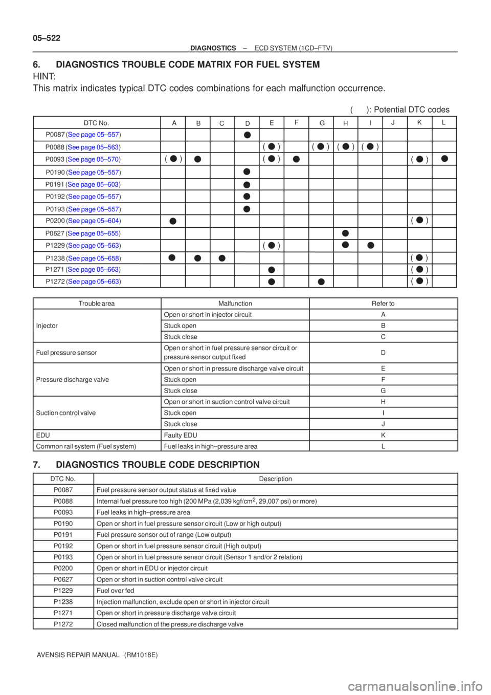
6. DIAGNOSTICS TROUBLE CODE MATRIX FOR FUEL SYSTEM
HINT:
This matrix indicates typical DTC codes combinations for each malfunctio\
n occurrence.
Trouble areaMalfunctionRefer to
Open or short in injector circuitA
InjectorStuck openBj
Stuck closeC
Fuel pressure sensorOpen or short in fuel pressure sensor circuit or
pressure sensor output fixedD
Open or short in pressure discharge valve circuitE
Pressure discharge valveStuck openFg
Stuck closeG
Open or short in suction control valve circuitH
Suction control valveStuck openI
Stuck closeJ
EDUFaulty EDUK
Common rail system (Fuel system)Fuel leaks in high±pressure areaL
7. DIAGNOSTICS TROUBLE CODE DESCRIPTION
DTC No.Description
P0087Fuel pressure sensor output status at fixed value
P0088Internal fuel pressure too high (200 MPa (2,039 kgf/cm2, 29,007 psi) or more)
P0093Fuel leaks in high±pressure area
P0190Open or short in fuel pressure sensor circuit (Low or high output)
P0191Fuel pressure sensor out of range (Low output)
P0192Open or short in fuel pressure sensor circuit (High output)
P0193Open or short in fuel pressure sensor circuit (Sensor 1 and/or 2 relati\
on)
P0200Open or short in EDU or injector circuit
P0627Open or short in suction control valve circuit
P1229Fuel over fed
P1238Injection malfunction, exclude open or short in injector circuit
P1271Open or short in pressure discharge valve circuit
P1272Closed malfunction of the pressure discharge valve
Page 656 of 5135

±
DIAGNOSTICS ECD SYSTEM(1CD±FTV)
05±597
AVENSIS REPAIR MANUAL (RM1018E)
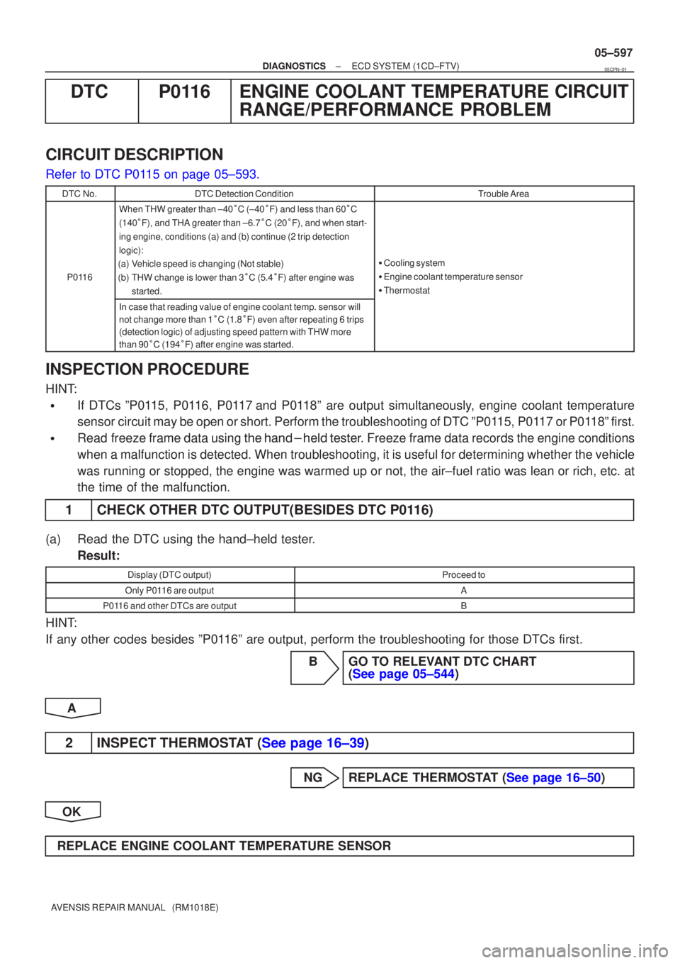
DTCP0116ENGINE COOLANT TEMPERATURE CIRCUIT
RANGE/PERFORMANCE PROBLEM
CIRCUIT DESCRIPTION
Refer to DTC P0115 on page 05±593.
DTC No.DTC Detection ConditionTrouble Area
P0116
When THW greater than ±40 \fC (±40 \fF) and less than 60 \fC
(140 \fF), and THA greater than ±6.7 \fC (20 \fF), and when start-
ing engine, conditions (a) and (b) continue (2 trip detection
logic):
(a)Vehicle speed is changing (Not stable)
(b)THW change is lower than 3 \fC (5.4 \fF) after engine was
started.
� Cooling system
� Engine coolant temperature sensor
� Thermostat
In case that reading value of engine coolant temp. sensor will
not change more than 1 \fC (1.8 \fF) even after repeating 6 trips
(detection logic) of adjusting speed pattern with THW more
than 90 \fC (194 \fF) after engine was started.
INSPECTION PROCEDURE
HINT:
�If DTCs ºP0115, P0116, P0117and P0118º are output simultaneously, engine coolant temperature
sensor circuit may be open or short. Perform the troubleshooting of DTC ºP0\
115, P0117 or P0118º first.
�Read freeze frame data using �����\b��������
�� . Freeze frame data records the engine conditions
when a malfunction is detected. When troubleshooting, it is useful for d\
etermining whether the vehicle
was running or stopped, the engine was warmed up or not, the air±fuel ra\
tio was lean or rich, etc. at
the time of the malfunction.
1CHECK OTHER DTC OUTPUT(BESIDES DTC P0116)
(a)Read the DTC using the hand±held tester. Result:
Display (DTC output)Proceed to
Only P0116 are outputA
P0116 and other DTCs are outputB
HINT:
If any other codes besides ºP0116º are output, perform the troubleshooting for those DTCs first.
BGO TO RELEVANT DTC CHART(See page 05±544)
A
2INSPECT THERMOSTAT (See page 16±39)
NGREPLACE THERMOSTAT (See page 16±50)
OK
REPLACE ENGINE COOLANT TEMPERATURE SENSOR
05CPN±01