Page 727 of 5135

A81481
EDU Wiring DiagramCOM3
COM1 COM2
Pressure
Discharge
Valve
Injector
INJ#1
INJ#4INJ#2INJ#3
PRV
GND
EDU Connector
Control
Circuit
DC/DC
Converter
BATTERY
IJT#1
IJT#4
IJT#2
IJT#3PRDIJF
ECM
Maximum 150 V
Confirmation
Pulse Command
Pulse
Warning:
Terminal J, I, H, K, L, M, N and S are high voltage
E5
E4
Maximum 150 V
05±604
±
DIAGNOSTICS ECD SYSTEM(1CD±FTV)
AVENSIS REPAIR MANUAL (RM1018E)
DTCP0200INJECTOR CIRCUIT / OPEN
HINT:
�For more information on the EDU, see page 05±517.
�If P0200 are present, Use the diagnostic trouble code matrix for fuel sy\
stem, see page 05±517.
CIRCUIT DESCRIPTION
The EDU has been adopted to drive the injector at high speeds. The EDU has \
realized high±speed driving
under high fuel pressure conditions using the DC/DC converter that provides a\
high±voltage, quick±charging
system.
Soon after the EDU receives an injection command signal (IJT) from the\
ECM, the EDU responds to the com-
mand with injector injection confirmation signal (IJF) when the current is\
applied to the injector.
05CPR±01
Page 731 of 5135

A81511
5 V/
Division
20 msec./Division INJFSignal Waveform
05±608
± DIAGNOSTICSECD SYSTEM (1CD±FTV)
AVENSIS REPAIR MANUAL (RM1018E)
(b) Reference: Inspect using the oscilloscope.
The correct waveform is as shown in the diagram on the
left.
Inspection PointsSpecified Condition
C and DCorrect waveform is as shown
INSPECTION PROCEDURE
HINT:
�If P0200 and P1271 are present simultaneously, there is open in the INJF wire harness between the
EDU and ECM, or there is open in the wire harness for both of the injector the pressure discharge valve.
�Read freeze frame data using ��� ��������� ��
�� . Freeze frame data records the engine conditions
when a malfunction is detected. When troubleshooting, it is useful for determining whether the vehicle
was running or stopped, the engine was warmed up or not, etc. at the time of the malfunction.
1 CHECK OTHER DTC OUTPUT(BESIDES DTC P0200)
(a) Connect the hand±held tester to the DLC3.
(b) Turn the ignition switch ON and push the hand±held tester main switch ON.
(c) Select the item ºDIAGNOSIS / OBD/MOBD / DTC INFO / CURRENT CODESº.
(d) Read the DTCs.
Result:
Display (DTC output)Proceed to
DTC P0200 and P1238 are outputA
Only DTC P0200 is outputB
B Go to step 3
A
2 READ VALUE OF HAND±HELD TESTER(COMPENSATION OF INJECTION
QUANTIFY BETWEEN CYLINDERS)
(a) Connect the hand±held tester to the DLC3.
(b) Turn the ignition switch ON and push the hand±held tester main switch ON.
(c) Start the engine.
(d) Select the item ºDIAGNOSIS / OBD/MOBD / DATA LIST / ALL / INJ VOLUME FBº and read its value
displayed on the hand±held tester.
Result:
STD ± 3 to 3 mm
3/st
Maximum ± 4.9 to 4.9 mm
3/st
(e) The cylinder that has a misspecification compensation value is a faulty cylinder, use the following flow-
chart to inspect and repair the cylinder.
GO
Page 735 of 5135

±
DIAGNOSTICS ECD SYSTEM(1CD±FTV)
05±603
AVENSIS REPAIR MANUAL (RM1018E)
DTCP0191FUEL RAIL PRESSURE SENSOR CIRCUIT
RANGE/PERFORMANCE
CIRCUIT DESCRIPTION
Refer to DTCs P0087 on page 05±557.
INSPECTION PROCEDURE
HINT:
�If DTCs ºP0087, P0190, P0192,and P0193º are output simultaneously, manifold absolute pressure
sensor circuit may be open or short. Perform the troubleshooting of DTC ºP0087, P0190, P019\
2,and
P0193º first.
�Read freeze frame data using the hand±held tester. Freeze frame data records the engine conditions
when a malfunction is detected. When troubleshooting, it is useful for deter\
mining whether the vehicle
was running or stopped, the engine was warmed up or not, etc. at the time o\
f the malfunction.
DTC No.DTC Detection ConditionTrouble Area
P0191Voltage output of the fuel pressure sensor for the common rail
is out of the standard range. (1 trip detection logic)�Fuel pressure sensor
1CHECK OTHER DTC OUTPUT(BESIDS DTC P0191)
(a)Read the DTC using the hand±held tester.
Result:
Display (DTC output)Proceed to
Only P0191 is outputA
P0191 and other DTCs are outputB
HINT:
If any other codes besides P0191 are output, perform the troubleshoot for \
those DTCs first.
BGO TO RELEVANT DTC CHART(See page 05±544)
A
REPLACE COMMON RAIL ASSY (FUEL PRESSURE SENSOR) (See page 11±78)
05CPQ±01
Page 741 of 5135

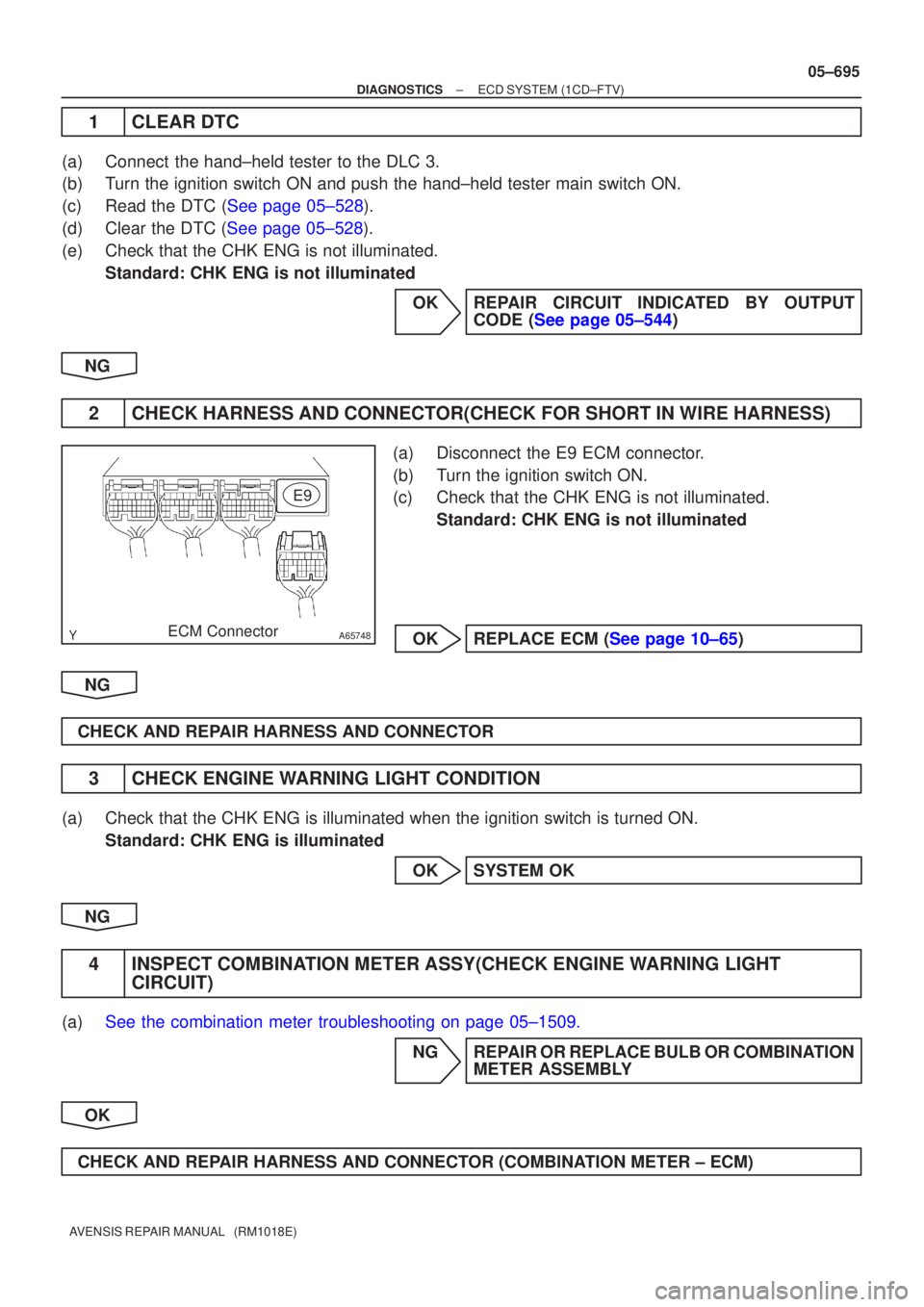
A65748ECM ConnectorE9
±
DIAGNOSTICS ECD SYSTEM(1CD±FTV)
05±695
AVENSIS REPAIR MANUAL (RM1018E)
1CLEAR DTC
(a)Connect the hand±held tester to the DLC 3.
(b)Turn the ignition switch ON and push the hand±held tester main switch \
ON.
(c)Read the DTC (See page 05±528).
(d)Clear the DTC (See page 05±528).
(e)Check that the CHK ENG is not illuminated.
Standard: CHK ENG is not illuminated
OKREPAIR CIRCUIT INDICATED BY OUTPUTCODE (See page 05±544)
NG
2CHECK HARNESS AND CONNECTOR(CHECK FOR SHORT IN WIRE HARNESS)
(a)Disconnect the E9 ECM connector.
(b)Turn the ignition switch ON.
(c)Check that the CHK ENG is not illuminated. Standard: CHK ENG is not illuminated
OKREPLACE ECM (See page 10±65)
NG
CHECK AND REPAIR HARNESS AND CONNECTOR
3CHECK ENGINE WARNING LIGHT CONDITION
(a)Check that the CHK ENG is illuminated when the ignition switch is turned\
ON. Standard: CHK ENG is illuminated
OKSYSTEM OK
NG
4INSPECT COMBINATION METER ASSY(CHECK ENGINE WARNING LIGHT CIRCUIT)
(a)See the combination meter troubleshooting on page 05±1509.
NG REPAIR OR REPLACE BULB OR COMBINATIONMETER ASSEMBLY
OK
CHECK AND REPAIR HARNESS AND CONNECTOR (COMBINATION METER ± ECM)
Page 747 of 5135

±
DIAGNOSTICS ECD SYSTEM(1CD±FTV)
05±685
AVENSIS REPAIR MANUAL (RM1018E)
DTCP2227BAROMETRIC PRESSURE CIRCUIT
RANGE/PERFORMANCE
CIRCUIT DESCRIPTION
Detect the atmospheric pressure using the atmospheric pressure sensor. Followed by the atmospheric pres-
sure, correct the injection timing, the injection volume and the amount of co\
mmon rail internal fuel pressure
and then they create optimum combustion.
DTC No.DTC Detection ConditionTrouble Area
P2227Atmospheric pressure sensor malfunction
(2 trip detection logic)�ECM
INSPECTION PROCEDURE
HINT:
Read freeze frame data using �����\b��������
�� . Freeze frame data records the engine conditions when
a malfunction is detected. When troubleshooting, it is useful for determi\
ning whether the vehicle was running
or stopped, the engine was warmed up or not, etc. at the time of the malfu\
nction.
1CHECK OTHER DTC OUTPUT(BESIDES DTC P2227)
(a)Read the DTC using the hand±held tester. Result:
Display (DTC output)Proceed to
P2227 and other DTCs are outputA
Only P2227 is outputB
HINT:
If any other codes besides P2227 are output, perform the troubleshooting f\
or those DTCs first.
BREPLACE ECM (See page 10±65)
A
GO TO RELEVANT DTC CHART (See page 05±544)
05CQ6±01
Page 756 of 5135
±
DIAGNOSTICS ECD SYSTEM(1CD±FTV)
05±673
AVENSIS REPAIR MANUAL (RM1018E)
DTCP1601INJECTOR CORRECTION CIRCUIT
MALFUNCTION (EEPROM)
CIRCUIT DESCRIPTION
DTC No.DTC Detection ConditionTrouble Area
P1601
�Injector compensation value is not registered
(1 trip detection logic)
� Wrong injector compensation value is registered
(1 trip detection logic)�Injector compensation code
� ECM
INSPECTION PROCEDURE
HINT:
Read freeze frame data using �����\b��������
�� . Freeze frame data records the engine conditions when
a malfunction is detected. When troubleshooting, it is useful for determi\
ning whether the vehicle was running
or stopped, the engine was warmed up or not, etc. at the time of the malfu\
nction.
1CHECK INJECTOR COMPENSATION CODE (See page 05±528)
NGSET INJECTOR COMPENSATION CODE (See page 05±528)
OK
REPLACE ECM (See page 10±65)
05CQ2±01
Page 757 of 5135

A81485
Fuel Pressure
Pressure Discharge Valve Operation Under Sudden Deceleration
Pressure Discharge Valve w/o Pressure Discharge Valve
Close
Accelerator Pedal
Opening Angle
Open
Close
Open
w/ Pressure Discharge Valve
TargetFuel Pressure TimeLong Time
±
DIAGNOSTICS ECD SYSTEM(1CD±FTV)
05±663
AVENSIS REPAIR MANUAL (RM1018E)
DTCP1271FUEL REGULATOR CIRCUIT MALFUNCTION
(EDU DRIVE)
DTCP1272FUEL PRESSURE REGULATOR MALFUNCTION
HINT:
�For more information on the pressure discharge valve and the common rail sy\
stem, see page 05±517.
�For more information on the EDU, see page 05±604.
�If P1271 and/or P1272 are present, use the diagnostic trouble code matrix for fuel syste\
m, see page
05±517.
CIRCUIT DESCRIPTION
The ECM controls the internal fuel pressure of the common rail by opening a\
nd closing the pressure dis-
charge valve. When sudden deceleration is occurred, the internal fuel pressure will temporarily become
higher than usual and combustion noise may result, therefore the ECM will open the valve temporarily to
discharge the pressure inside the common rail. Also, the pressure discharge valve open\
s when the ignition
switch is turned OFF, and the internal pressure is then promptly discharged.
05CQ1±01
Page 762 of 5135

A81513
5 V/
Division
20 msec./Division PRDSignal Waveform
A82882
5 V/
Division
20 msec./Division INJFSignal Waveform
05±668
± DIAGNOSTICSECD SYSTEM (1CD±FTV)
AVENSIS REPAIR MANUAL (RM1018E)
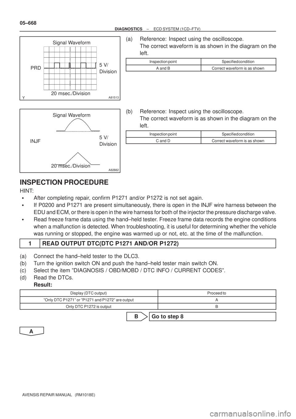
(a) Reference: Inspect using the oscilloscope.
The correct waveform is as shown in the diagram on the
left.
Inspection pointSpecified condition
A and BCorrect waveform is as shown
(b) Reference: Inspect using the oscilloscope.
The correct waveform is as shown in the diagram on the
left.
Inspection pointSpecified condition
C and DCorrect waveform is as shown
INSPECTION PROCEDURE
HINT:
�After completing repair, confirm P1271 and/or P1272 is not set again.
�If P0200 and P1271 are present simultaneously, there is open in the INJF wire harness between the
EDU and ECM, or there is open in the wire harness for both of the injector the pressure discharge valve.
�Read freeze frame data using the hand±held tester. Freeze frame data records the engine conditions
when a malfunction is detected. When troubleshooting, it is useful for determining whether the vehicle
was running or stopped, the engine was warmed up or not, etc. at the time of the malfunction.
1 READ OUTPUT DTC(DTC P1271 AND/OR P1272)
(a) Connect the hand±held tester to the DLC3.
(b) Turn the ignition switch ON and push the hand±held tester main switch ON.
(c) Select the item ºDIAGNOSIS / OBD/MOBD / DTC INFO / CURRENT CODESº.
(d) Read the DTCs.
Result:
Display (DTC output)Proceed to
ºOnly DTC P1271º or ºP1271 and P1272º are outputA
Only DTC P1272 is outputB
B Go to step 8
A