Page 2515 of 5135
26±19
AVENSIS REPAIR MANUAL (RM1018E)
19. CONNECT FRONT SUSPENSION ARM SUB±ASSY
LOWER NO.1 LH
(a) Connect")
C80293
F13686
C80889
±
FRONT SUSPENSION FRONT SUSPENSION ARM SUB±ASSY LOWER NO.1
LH (ATM)26±19
AVENSIS REPAIR MANUAL (RM1018E)
19. CONNECT FRONT SUSPENSION ARM SUB±ASSY
LOWER NO.1 LH
(a) Connect the lower suspension arm to the lower ball joint
with the 2 nuts and bolt.
Torque: 89 N �m (908 kgf �cm, 66 ft �lbf)
20. CONNECT FRONT SUSPENSION ARM SUB±ASSY LOWER NO.1 RH
HINT:
Connect the RH side by the same procedures as the LH side.
21.INSTALL TIE ROD END SUB±ASSY LH (See page 30±6)
22. INSTALL TIE ROD END SUB±ASSY RH
HINT:
Connect the RH side by the same procedures as the LH side. 23. CONNECT FRONT STABILIZER LINK ASSY LH
(a) Install the stabilizer bar link with the nut.Torque: 74 N �m (755 kgf �cm, 55 ft �lbf)
HINT:
If the ball joint turns together with the nut, use a hexagon (6 mm)
wrench to hold the stud.
24. CONNECT FRONT STABILIZER LINK ASSY RH
HINT:
Install the RH side by the same procedures as the LH side.
25. STABILIZE SUSPENSION
(a) Install the front wheel and jack down the vehicle. Torque: 103 N �m (1,050 kgf �cm, 76 ft �lbf)
(b) Bounce the vehicle up and down several times to stabilize the suspension\
.
26. FULLY TIGHTEN FRONT SUSPENSION ARMSUB±ASSY LOWER NO.1 LH
(a) Fully tighten the 2 bolts and nut.
Torque: 137 N �m (1,400 kgf �cm, 101 ft �lbf)
Page 2518 of 5135
2600M±04
F13686
C80880
F13683
F44622
26±10
±
FRONT SUSPENSION FRONT SHOCK ABSORBER WITH COIL SPRING
AVENSIS REPAIR MANUAL (RM1018E)
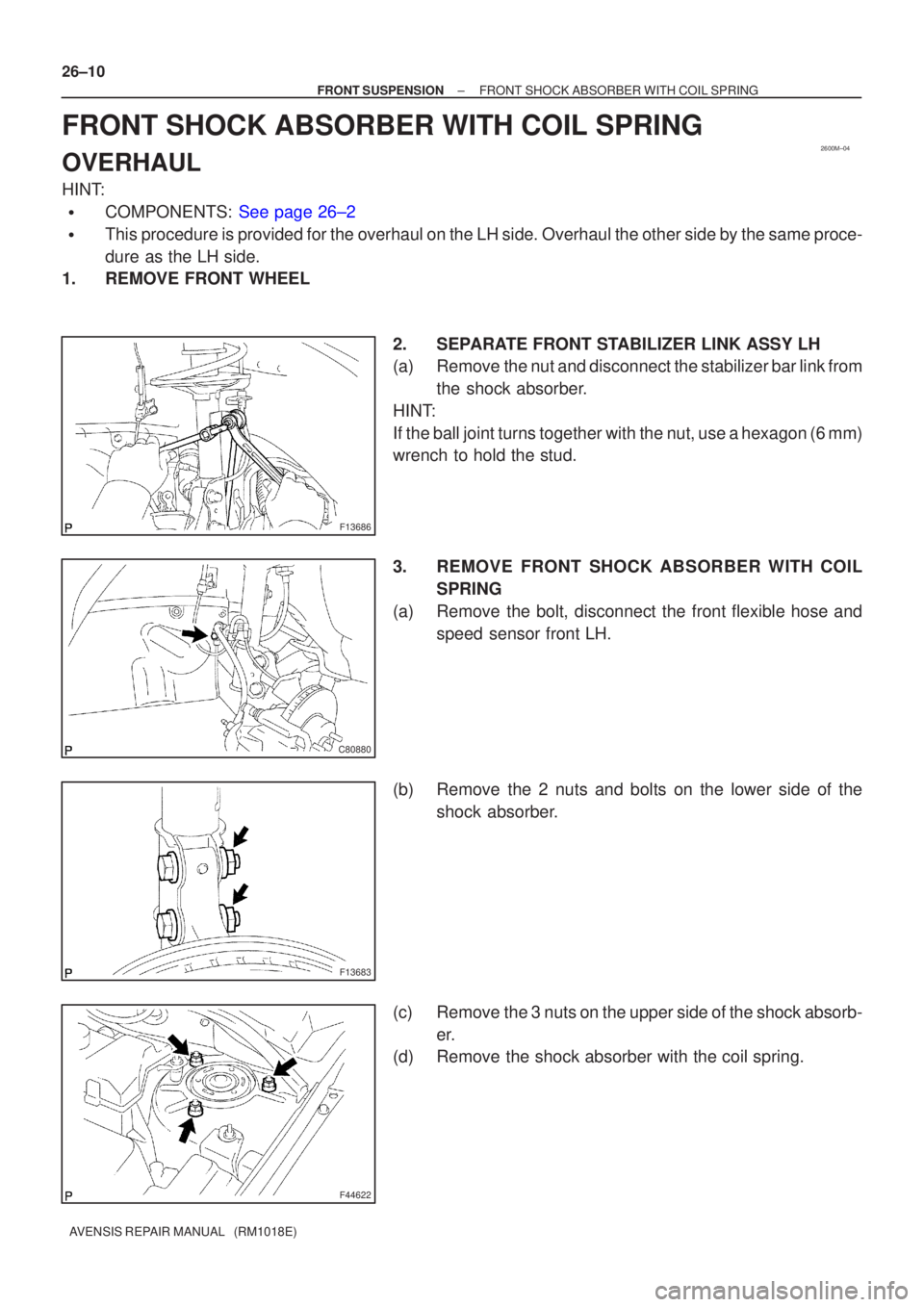
FRONT SHOCK ABSORBER WITH COIL SPRING
OVERHAUL
HINT:
�COMPONENTS: See page 26±2
�This procedure is provided for the overhaul on the LH side. Overhaul the oth\
er side by the same proce-
dure as the LH side.
1. REMOVE FRONT WHEEL
2. SEPARATE FRONT STABILIZER LINK ASSY LH
(a) Remove the nut and disconnect the stabilizer bar link fromthe shock absorber.
HINT:
If the ball joint turns together with the nut, use a hexagon (6 mm)
wrench to hold the stud.
3. REMOVE FRONT SHOCK ABSORBER WITH COIL SPRING
(a) Remove the bolt, disconnect the front flexible hose and speed sensor front LH.
(b) Remove the 2 nuts and bolts on the lower side of the shock absorber.
(c) Remove the 3 nuts on the upper side of the shock absorb- er.
(d) Remove the shock absorber with the coil spring.
Page 2525 of 5135
F13683
26±8
± FRONT SUSPENSIONFRONT WHEEL ALIGNMENT
AVENSIS REPAIR MANUAL (RM1018E)
7. ADJUST CAMBER
NOTICE:
After the camber has been adjusted, inspect the toe±in.
(a) Remove the front wheel.
(b) Remove the 2 bolts and nuts on the lower side of the
shock absorber.
If reusing the bolts and/or nuts, coat the threads of nuts with en-
gine oil.
(c) Clean the installation surfaces of the shock absorber and
the steering knuckle.
(d) Temporarily install the 2 bolts and nuts.
Page 2526 of 5135

F44962
+
±
F13685
1
2
F12938
Bolt
Adjusting
ValueSet BoltAdjusting Bolt90105±17008 90105±17009
90105±17010 90105±17011
121212121 Dot
2 Dots3 Dots
±1�30' ± ±1�15'
±1�15' ± ±1�00'
±1�00' ± ±45'
±45' ± ±30'
±30' ± ±15'
0' ± 15'
15' ± 30'
30' ± 45'
45' ± 1����
1�00' ± 1�15' ±15' ± 0'
1�15' ± 1�30'
± FRONT SUSPENSIONFRONT WHEEL ALIGNMENT
26±9
AVENSIS REPAIR MANUAL (RM1018E)
(e) Adjust the camber by pushing or pulling the lower side of
the shock absorber in the direction in which the camber
adjustment is required.
(f) Tighten the nuts.
Torque: 220 N�m (2,240 kgf�cm, 162 ft�lbf)
(g) Install the front wheel.
Torque: 103 N´m (1,050 kgf´cm, 76 ft´lbf)
(h) Check the camber.
HINT:
�Adjust the camber to the center of the specified value as
much as possible.
�Adjusting value for the set bolts is 6' ± 30' (0.1� ± 0.5�).
If the camber is not within the specified value, using the follow-
ing table, estimate how much additional camber adjustment will
be required, and select the camber adjusting bolt.
NOTICE:
Tighten the adjusting bolt with a washer and a new nut.
(i) Perform the procedure mentioned above again. At step
(b), replace 1 or 2 selected bolts.
HINT:
When replacing the 2 bolts, replace 1 bolt for each time.
Page 2528 of 5135

REPLACEMENT
HINT:
Replace the RH side by the same")
300JY±01
������F45751
SST
C80291
F44775
C67088
30±22
±
DRIVE SHAFT / PROPELLER SHAFT FRONT AXLE HUB SUB±ASSY LH
AVENSIS REPAIR MANUAL (RM1018E)
REPLACEMENT
HINT:
Replace the RH side by the same procedures as the LH side.
1. REMOVE FRONT WHEEL
2.SEPARATE FRONT STABILIZER LINK ASSY LH (See page 30±6) 3. REMOVE FRONT AXLE HUB LH NUT
(a) Using SST and a hammer, unstake the staked part of theaxle hub LH nut.
SST 09930±00010
(b) While applying the brakes, remove the axle hub LH nut.
4. DISCONNECT SPEED SENSOR FRONT LH
(a) Remove the bolt, and disconnect the speed sensor wire and flexible hose from the shock absorber.
(b) Remove the bolt, separate the speed sensor front LH from the steering knuckle.
NOTICE:
�Be careful not to damage the speed sensor.
�Prevent foreign matter from attaching to the speed
sensor.
5. SEPARATE FRONT DISC BRAKE CALIPER ASSY LH
(a) Removing the 2 bolts, separate the disc brake caliper assy LH from the steering knuckle.
NOTICE:
Use a string or other device to keep the brake caliper from
hanging down.
Page 2559 of 5135
G23878
Inner side
Stopper Ring
G23876
G25774
27±30
±
REAR SUSPENSION STABILIZER BAR REAR
AVENSIS REPAIR MANUAL (RM1018E)
5. INSTALL STABILIZER BAR REAR
(a) Install the 2 stabilizer bush rear to each stabilizer bar rear.
HINT:
Install the stabilizer bush rear to the outer side of the stopper
ring on the stabilizer bar.
(b) Install the stabilizer bar rear and 2 rear stabilizer bar bracket No.3 with 2 bolts and 2 nuts.
Torque: 35 N �m (357 kgf �cm, 26 ft �lbf)
6. INSTALL REAR STABILIZER LINK ASSY LH
(a) Install the rear stabilizer link assy LH with the 2 nuts. Torque: 44 N �m (449 kgf �cm, 32 ft �lbf)
HINT:
If the ball joint turns together with the nut, use a hexagon (5 mm)
wrench to hold the stud.
7. INSTALL REAR STABILIZER LINK ASSY RH
HINT:
Install the RH side by the same procedures as the LH side.
8.INSPECT AND ADJUST REAR WHEEL ALIGNMENT (See page 27±4)
Page 2565 of 5135
270E3±01
G23867
G25771
G25772
G25775
±
REAR SUSPENSION REAR SUSPENSION ARM ASSY NO.1 LH
27±15
AVENSIS REPAIR MANUAL (RM1018E)
REAR SUSPENSION ARM ASSY NO.1 LH
OVERHAUL
HINT:
COMPONENTS: See page 27±2.
1. REMOVE REAR WHEEL
2. SEPARATE PARKING BRAKE CABLE ASSY NO.3
(a) Remove the 2 bolts, and separate the parking brake cableassy No.3.
3. DISCONNECT SKID CONTROL SENSOR WIRE
(a) Disconnect the skid control sensor connector.
(b) Remove the bolt and wire bracket.
4. SEPARATE REAR STABILIZER LINK ASSY LH
(a) Remove the nut, and separate the rear stabilizer link assy LH.
HINT:
If the ball joint turns together with the nut, use a hexagon (5 mm)
wrench to hold the stud.
5. REMOVE LOWER CONTROL ARM ASSY LH
(a) Support the rear suspension arm assy No.1 LH.
Page 2598 of 5135

REAR AXLE LH HUB BOLT
REPLACEMENT")
300K0±01
������F45577
Hold
Turn
SST
������F45578
Hold
Turn
Nut
Washer
30±36
±
DRIVE SHAFT / PROPELLER SHAFT REAR AXLE LH HUB BOLT
AVENSIS REPAIR MANUAL (RM1018E)
REAR AXLE LH HUB BOLT
REPLACEMENT
HINT:
�COMPONENTS: See page 30±30
�Replace the RH side by the same procedures as the LH side.
1. REMOVE REAR WHEEL
2. SEPARATE REAR DISC BRAKE CALIPER ASSY LH
(a) Removing the 2 bolts and rear disc brake caliper assy.
NOTICE:
Use a string or other device to keep the brake caliper from hanging down\
.
3. REMOVE REAR DISC
4. REMOVE REAR AXLE LH HUB BOLT
(a) Turn the axle hub to move the LH hub bolt and SST, thatare to be removed, to the place shown in the illustration.
NOTICE:
Do not replace the hub bolt in any places other than that in
the illustration.
(b) Using SST and a hammer handle or an equivalent to hold the axle hub, remove the LH hub bolt.
SST 09628±10011
5. INSTALL REAR AXLE LH HUB BOLT
(a) Install a washer and nut to a new LH hub bolt as shown in the illustration.
(b) Using a hammer handle or an equivalent to hold the axle
hub, install the LH hub bolt by torquing the nut.
6. INSTALL REAR DISC
7. INSTALL REAR DISC BRAKE CALIPER ASSY LH
(a) Install the rear disc brake caliper assy with the 2 bolts. Torque: 47 N �m (475 kgf �cm, 34 ft �lbf)
8. INSTALL REAR WHEEL Torque: 103 N �m (1,050 kgf �cm, 76 ft �lbf)

7. ADJUST CAMBER
NOTICE:
After the camber has been adjusted, inspect the toe±in.
(a) Remove the front wheel.
(b")

5. INSTALL STABILIZER BAR REAR
(a) Install the 2 stabilizer bush rear to ea")

REAR SUSPENSION ARM ASSY NO.1 LH
OVERHAUL
HINT:
COMPONENTS: See page")