Page 760 of 5135
05±666
± DIAGNOSTICSECD SYSTEM (1CD±FTV)
AVENSIS REPAIR MANUAL (RM1018E)
P1272:
Required sensorsFuel pressure sensor
Frequency of operationOnce per driving cycle
Duration1 sec.
CHK ENG operation2 driving cycles
TYPICAL ENABLING CONDITIONS
P1271:
Specification
Drive the vehicle at 50 km/h with the 3 rd transmission gear and then decelerate it by completly releasing the accelerator pedal
P1272:
ItemSpecificationItemMinimumMaximum
Fuel pressure30 MPa (306 kgf/cm2, 4,351 psi)±
Fuel temperature0�C±
Battery voltage11 V±
The monitor will not run if the fuel pressure sensor, or pressure discharge valve circuit, or fuel temp. sensor is malfunctioning
TYPICAL MALFUNCTION THRESHOLDS
P1271:
Threshold
If the confirmation signals from the EDU is not present, despite the ECM sending the command signals regularly during decelerating
P1272:
Threshold
If the internal pressure stays beyond the specified level after the ignition switch was turned OFF
Page 765 of 5135

A66060
E13
ECM Connector
PRD
E1
E12
A81513
5 V/
Division
20 msec./Division
PRD
Signal Waveform
±
DIAGNOSTICS ECD SYSTEM(1CD±FTV)
05±671
AVENSIS REPAIR MANUAL (RM1018E)
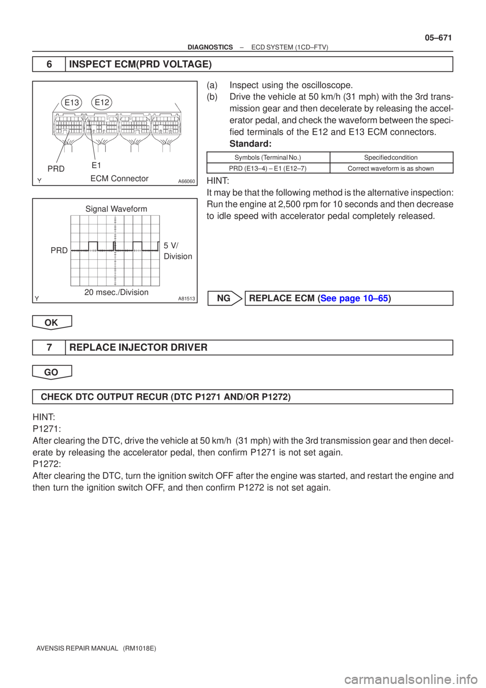
6INSPECT ECM(PRD VOLTAGE)
(a)Inspect using the oscilloscope.
(b)Drive the vehicle at 50 km/h (31 mph) with the 3rd trans-
mission gear and then decelerate by releasing the accel-
erator pedal, and check the waveform between the speci-
fied terminals of the E12 and E13 ECM connectors.
Standard:
Symbols (Terminal No.)Specified condition
PRD (E13±4) ± E1 (E12±7)Correct waveform is as shown
HINT:
It may be that the following method is the alternative inspection:
Run the engine at 2,500 rpm for 10 seconds and then decrease
to idle speed with accelerator pedal completely released.
NGREPLACE ECM (See page 10±65)
OK
7 REPLACE INJECTOR DRIVER
GO
CHECK DTC OUTPUT RECUR (DTC P1271 AND/OR P1272)
HINT:
P1271:
After clearing the DTC, drive the vehicle at 50 km/h (31 mph) with the 3rd\
transmission gear and then decel-
erate by releasing the accelerator pedal, then confirm P1271 is not set again\
.
P1272:
After clearing the DTC, turn the ignition switch OFF after the engine was sta\
rted, and restart the engine and
then turn the ignition switch OFF, and then confirm P1272 is not set again.
Page 766 of 5135

05±672
±
DIAGNOSTICS ECD SYSTEM(1CD±FTV)
AVENSIS REPAIR MANUAL (RM1018E)
8READ VALUE OF HAND±HELD TESTER
(a)Connect the hand±held tester to the DLC3.
(b)Turn the ignition switch ON and push the hand±held tester main switch \
ON.
(c)Start the engine.
(d)Select the item ºDIAGNOSIS / OBD/MOBD / DATA LIST / ALL / COMN RAIL PRESSº and read its value displayed on the hand±held tester.
(e)Check if the internal fuel pressure of the common rail drops below approximat\
ely 5 MPa within approxi- mately 1 second after the ignition switch is turned OFF at idling.
Result:
Pressure DisplayedProceed to
5 MPa or moreA
5 MPa or lessB
BCHECK DTC OUTPUT RECUR (DTC P1271 AND/ OR P1272)
HINT:
P1271:
After clearing the DTC, drive the vehicle at 50 km/h (31 mph)
with the 3rd transmission gear and then decelerate by releasing
the accelerator pedal, then confirm P1271 is not set again.
P1272:
After clearing the DTC, turn the ignition switch OFF after the en-
gine was started, and restart the engine and then turn the igni-
tion switch OFF, and then confirm P1272 is not set again.
A
9REPLACE COMMON RAIL ASSY(PRESSURE DISCHARGE VALVE)
(See page 11±78)
GO
CHECK DTC OUTPUT RECUR (DTC P1271 AND/OR P1272)
HINT:
P1271:
After clearing the DTC, drive the vehicle at 50 km/h (31 mph) with the 3rd\
transmission gear and then decel-
erate by releasing the accelerator pedal, then confirm P1271 is not set again\
.
P1272:
After clearing the DTC, turn the ignition switch OFF after the engine was sta\
rted, and restart the engine and
then turn the ignition switch OFF, and then confirm P1272 is not set again.
Page 907 of 5135
![TOYOTA AVENSIS 2005 Service Repair Manual D26545
E1
ECT Solenoid
ECM
28
E2 BR
6
30
THO
E13
1 E2
THO O
O
VE13 05±882
± DIAGNOSTICSELECTRONIC CONTROLLED AUTOMATIC
TRANSAXLE [ECT] (U241E(1AZ±FE))
AVENSIS REPAIR MANUAL (RM1018E)
DTC P0710/38 TOYOTA AVENSIS 2005 Service Repair Manual D26545
E1
ECT Solenoid
ECM
28
E2 BR
6
30
THO
E13
1 E2
THO O
O
VE13 05±882
± DIAGNOSTICSELECTRONIC CONTROLLED AUTOMATIC
TRANSAXLE [ECT] (U241E(1AZ±FE))
AVENSIS REPAIR MANUAL (RM1018E)
DTC P0710/38](/manual-img/14/57441/w960_57441-906.png)
D26545
E1
ECT Solenoid
ECM
28
E2 BR
6
30
THO
E13
1 E2
THO O
O
VE13 05±882
± DIAGNOSTICSELECTRONIC CONTROLLED AUTOMATIC
TRANSAXLE [ECT] (U241E(1AZ±FE))
AVENSIS REPAIR MANUAL (RM1018E)
DTC P0710/38 TRANSMISSION FLUID TEMPERATURE
SENSOR ºAº CIRCUIT
DTC P0712/38 TRANSMISSION FLUID TEMPERATURE
SENSOR ºAº CIRCUIT LOW INPUT
DTC P0713/38 TRANSMISSION FLUID TEMPERATURE
SENSOR ºAº CIRCUIT HIGH INPUT
CIRCUIT DESCRIPTION
The ATF temperature sensor converts the fluid temperature into a resistance value which is input into the
ECM.
DTC No.DTC Detection ConditionTrouble Area
P0710/38
(a) and (b) is detected momentary within 0.5 sec. when neither
P0712 or P0713 is not detected (1±trip detection logic)
(a) ATF temperature sensor resistance is less than 79 ��
(b) ATF temperature sensor resistance is more than 156 k��
HINT:
Wthin 0.5 sec. the malfunction switches from (a) to (b) or from
(b) to (a)
�Open or short in ATF temperature sensor circuit
�ATF temperature sensor
P0712/38ATF temperature sensor resistance is less than 79 ��for 0.5
sec. or more (1±trip detection logic)�ECM
P0713/38
DTC is detected for 0.5 sec. or more (1±trip detection logic)
ATF temperature sensor resistance is more than 156 k��after
started engine for 15 minutes or more
WIRING DIAGRAM
05C8T±01
Page 908 of 5135
![TOYOTA AVENSIS 2005 Service Repair Manual C54864
THO
E2
C95813THOE2
± DIAGNOSTICSELECTRONIC CONTROLLED AUTOMATIC
TRANSAXLE [ECT] (U241E(1AZ±FE))05±883
AVENSIS REPAIR MANUAL (RM1018E)
INSPECTION PROCEDURE
1 INSPECT TRANSMISSION WIRE(ATF T TOYOTA AVENSIS 2005 Service Repair Manual C54864
THO
E2
C95813THOE2
± DIAGNOSTICSELECTRONIC CONTROLLED AUTOMATIC
TRANSAXLE [ECT] (U241E(1AZ±FE))05±883
AVENSIS REPAIR MANUAL (RM1018E)
INSPECTION PROCEDURE
1 INSPECT TRANSMISSION WIRE(ATF T](/manual-img/14/57441/w960_57441-907.png)
C54864
THO
E2
C95813THOE2
± DIAGNOSTICSELECTRONIC CONTROLLED AUTOMATIC
TRANSAXLE [ECT] (U241E(1AZ±FE))05±883
AVENSIS REPAIR MANUAL (RM1018E)
INSPECTION PROCEDURE
1 INSPECT TRANSMISSION WIRE(ATF TEMPERATURE SENSOR)
(a) Disconnect the transmission wire connector from the
transaxle.
(b) Measure the resistance between terminals THO and E2.
OK:
Resistance: 79 � to 156 k�
(c) Check the continuity between the wire harness side con-
nectors.
OK:
Standard (Check for a short):
SymbolsSpecified condition
THO ± Body groundNo continuityE2 ± Body groundNo continuity
NG REPAIR OR REPLACE TRANSMISSION WIRE
OK
2 CHECK HARNESS AND CONNECTOR(TRANSMISSION WIRE ± ECM)
(a) Connect the transmission wire connector to the transaxle.
(b) Disconnect the ECM connector.
(c) Measure the resistance between terminals THO and E2.
OK:
Resistance: 79 � to 156 k�
(d) Check the continuity between the wire harness side con-
nectors.
OK:
Standard (Check for a short):
SymbolsSpecified condition
THO ± Body groundNo continuityE2 ± Body groundNo continuity
NG REPAIR OR REPLACE HARNESS OR
CONNECTOR
OK
CHECK AND REPLACE ECM
Page 909 of 5135
)05±879
AVENSIS REPAIR MANUAL (RM1018E)
PROBLEM SYMPTOMS TABLE
HINT:
If a normal code is displayed during the TOYOTA AVENSIS 2005 Service Repair Manual 0567W±11
±
DIAGNOSTICS ELECTRONIC CONTROLLED AUTOMATIC
TRANSAXLE [ECT](U241E(1AZ±FE))05±879
AVENSIS REPAIR MANUAL (RM1018E)
PROBLEM SYMPTOMS TABLE
HINT:
If a normal code is displayed during the](/manual-img/14/57441/w960_57441-908.png)
0567W±11
±
DIAGNOSTICS ELECTRONIC CONTROLLED AUTOMATIC
TRANSAXLE [ECT](U241E(1AZ±FE))05±879
AVENSIS REPAIR MANUAL (RM1018E)
PROBLEM SYMPTOMS TABLE
HINT:
If a normal code is displayed during the DTC check but the trouble still o\
ccurs, check the circuits for each
symptom in the order given in the charts on the following pages and proceed to \
the page given for trouble-
shooting.
The Matrix Chart is divided into 3 chapters.
�If the instruction ºProceed to next circuit inspection shown on matri\
x chartº is given in the flow chart
for each circuit, proceed to the circuit with the next highest number in the table to continue the check.
�If the trouble still occurs even though there are no abnormalities in any of the other circuits, then ch\
eck
and replace the ECM.
CHAPTER 1: ELECTRONIC CIRCUIT MATRIX CHART
SymptomSuspect AreaSee page
No up±shift (A particular gear, from 1st to O/D gear, is not up±
shifted)ECM01±32
No down±shift (A particular gear, from O/D to 1st gear, is not
down±shifted)ECM01±32
No lock±up or No lock±up off
4. Stop light switch circuit
5. Engine coolant temp. sensor circuit
6. Throttle position sensor circuit
7. ECM05±905
05±161
05±161
01±32
Shift point too high or too lowECM01±32
No gear change by shifting into º+º or º±º while the shif\
t lever is in
the Sposition1. Transmission control switch circuit
2. ECM05±91001±32
Up±shift to O/D from 3rd while engine is cold
1. Engine coolant temp. sensor circuit
2. ATF temp. sensor circuit
3. ECM05±161
05±88201±32
Harsh engagement (N � D)ECM01±32
Harsh engagement (Lock±up)ECM01±32
Harsh engagement (Any driving range)ECM01±32
Poor accelerationECM01±32
Engine stalls when starting off or stoppingECM01±32
No kick±down1. Kick±down switch circuit
2. ECM05±908
01±32
Page 913 of 5135
0567R±11
D30682
Combination Meter
(MIL)
Europe spec: Stop Lamp
Switch Assy
Shift Lock Control Unit
(Transmission Control Switch)
Shift Solenoid Valve SLT
Shift Solenoid Valve SL1ECM
DLC3
Park/neutral Position
Switch Assy
Shift Solenoid Valve SL2
Shift Solenoid Valve DSLShift Solenoid
Valve S4
Transmission Wire
(ATF Temperature Sensor) Speed Sensor (NT)
Speed Sensor (NC)
Kick±down Switch
± DIAGNOSTICSELECTRONIC CONTROLLED AUTOMATIC
TRANSAXLE [ECT] (U241E(1AZ±FE))05±877
AVENSIS REPAIR MANUAL (RM1018E)
LOCATION
Page 914 of 5135
)
AVENSIS REPAIR MANUAL (RM1018E)
DIAGNOSTIC TROUBLE CODE CHART
If a DTC is displayed during the DTC che TOYOTA AVENSIS 2005 Service Repair Manual 0567Q±08
05±876±
DIAGNOSTICS ELECTRONIC CONTROLLED AUTOMATIC
TRANSAXLE [ECT](U241E(1AZ±FE))
AVENSIS REPAIR MANUAL (RM1018E)
DIAGNOSTIC TROUBLE CODE CHART
If a DTC is displayed during the DTC che](/manual-img/14/57441/w960_57441-913.png)
0567Q±08
05±876±
DIAGNOSTICS ELECTRONIC CONTROLLED AUTOMATIC
TRANSAXLE [ECT](U241E(1AZ±FE))
AVENSIS REPAIR MANUAL (RM1018E)
DIAGNOSTIC TROUBLE CODE CHART
If a DTC is displayed during the DTC check, check the circuit listed in th\
e table below and proceed to the
page given.
*
1 : ± ... MIL does not light / � ... MIL light up
DTC No.
(See Page)Detection ItemTrouble AreaMIL *Memory
P0500/42 (05±240)Vehicle Speed Sensor ºAº
� Combination meter
� Open or short in vehicle speed sensor circuit
� Vehicle speed sensor
� ECM
��
P0710/38
(05±882)Transmission Fluid Temperature
Sensor ºAº Circuit��
P0712/38(05±882)Transmission Fluid Temperature
Sensor ºAº Circuit Low Input� Open or short in ATF temperature sensor circuit
� ATF temperature sensor
�
ECM
��
P0713/38
(05±882)Transmission Fluid Temperature
Sensor ºAº Circuit High Input
�ECM
��
P0717/37(05±884)Turbine Speed Sensor Circuit No
Signal
� Open or short in speed sensor (NT) circuit
� Speed sensor (NT)
� ECM
� Automatic transaxle assembly
��
P0748/62
(05±886)Pressure Control Solenoid ºAº
Electrical
(Shift Solenoid Valve SL1)� Open or short in shift solenoid valve SL1 circuit
� Shift solenoid valve SL1
� ECM
��
P0778/63
(05±886)Pressure Control Solenoid ºBº
Electrical
(Shift Solenoid Valve SL2)� Open or short in shift solenoid valve SL2 circuit
� Shift solenoid valve SL2
� ECM
��
P0793/67
(05±892)Intermediate Shaft Speed Sen-
sor ºAº� Open or short in speed sensor (NC) circuit
� Speed sensor (NC)
� ECM
��
P0982/65
(05±886)Shift Solenoid ºDº Control Circuit
Low (Shift Solenoid Valve S4)� Open or short in shift solenoid valve S4 circuit
Shift l id l S4
��
P0983/65
(05±886)Shift Solenoid ºDº Control Circuit
High (Shift Solenoid Valve S4)� Shift solenoid valve S4
� ECM
��
P2716/77
(05±894)Pressure Contorl Solenoid ºDº
Electrical
(Shift Solenoid Valve SLT)� Open or short in shift solenoid valve SLT circuit
� Shift solenoid valve SLT
� ECM
±�
P2769/64
(05±897)Torque Converter Clutch Sole-
noid Circuit Low
(Shift Solenoid Valve DSL)
� Open or short in shift solenoid valve DSL circuit
Shift l id l DSL
±�
P2770/64
(05±897)Torque Converter Clutch Sole-
noid Circuit High
(Shift Solenoid Valve DSL)� Shift solenoid valve DSL
� ECM
±�