Page 2602 of 5135
G21543
F44820
������F45267
30±34
±
DRIVE SHAFT / PROPELLER SHAFT REAR AXLE CARRIER SUB±ASSY LH
AVENSIS REPAIR MANUAL (RM1018E)
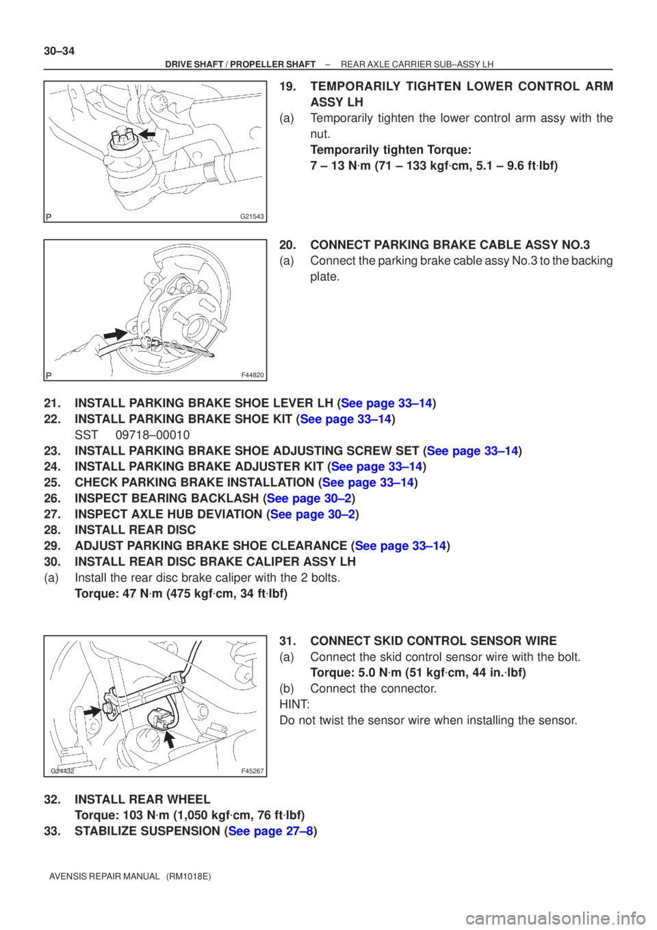
19.TEMPORARILY TIGHTEN LOWER CONTROL ARM ASSY LH
(a)Temporarily tighten the lower control arm assy with the
nut.
Temporarily tighten Torque:
7 ± 13 N �m (71 ± 133 kgf �cm, 5.1 ± 9.6 ft �lbf)
20.CONNECT PARKING BRAKE CABLE ASSY NO.3
(a)Connect the parking brake cable assy No.3 to the backing plate.
21.INSTALL PARKING BRAKE SHOE LEVER LH (See page 33±14)
22.INSTALL PARKING BRAKE SHOE KIT (See page 33±14) SST 09718±00010
23.INSTALL PARKING BRAKE SHOE ADJUSTING SCREW SET (See page 33±14)
24.INSTALL PARKING BRAKE ADJUSTER KIT (See page 33±14)
25.CHECK PARKING BRAKE INSTALLATION (See page 33±14)
26.INSPECT BEARING BACKLASH (See page 30±2)
27.INSPECT AXLE HUB DEVIATION (See page 30±2)
28. INSTALL REAR DISC
29.ADJUST PARKING BRAKE SHOE CLEARANCE (See page 33±14)
30. INSTALL REAR DISC BRAKE CALIPER ASSY LH
(a) Install the rear disc brake caliper with the 2 bolts. Torque: 47 N �m (475 kgf �cm, 34 ft �lbf)
31. CONNECT SKID CONTROL SENSOR WIRE
(a) Connect the skid control sensor wire with the bolt. Torque: 5.0 N �m (51 kgf �cm, 44 in. �lbf)
(b) Connect the connector.
HINT:
Do not twist the sensor wire when installing the sensor.
32. INSTALL REAR WHEEL Torque: 103 N �m (1,050 kgf �cm, 76 ft �lbf)
33.STABILIZE SUSPENSION (See page 27±8)
Page 2603 of 5135
±
DRIVE SHAFT / PROPELLER SHAFT REAR AXLE CARRIER SUB±ASSY LH
30±35
AVENSIS REPAIR MANUAL (RM1018E)
34. FULLY TIGHTEN UPPER CONTROL ARM ASSY
(a) Fully tighten the bolt.
Torque: 74 N �m (755 kgf �cm, 55 ft �lbf)
NOTICE:
When installing the bolt, hold the nut not to rotate.
35. FULLY TIGHTEN REAR SUSPENSION ARM ASSY NO.1 LH
(a) Fully tighten the nut (ball joint side). Torque: 105 N �m (1,071 kgf �cm, 77 ft �lbf)
(b) Install the clip.
NOTICE:
If the holes for the clip are not aligned, tighten the nut up to 60 � further.
(c) Fully tighten the bolt and nut.
Torque: 74 N �m (755 kgf �cm, 55 ft �lbf)
NOTICE:
When installing the bolt, hold the nut not to rotate.
36. FULLY TIGHTEN LOWER CONTROL ARM ASSY LH
(a) Fully tighten the nut. Torque: 60 N �m (612 kgf �cm, 44 ft �lbf)
(b) Install the clip.
NOTICE:
If the holes for the clip are not aligned, tighten the nut up to 60 � further.
(c) Fully tighten the bolt (member side). Torque: 105 N �m (1,071 kgf �cm, 77 ft �lbf)
NOTICE:
When installing the bolt, hold the nut not to rotate.
37.INSPECT AND ADJUST PARKING BRAKE LEVER TRAVEL (See page 33±2)
38.INSPECT AND ADJUST REAR WHEEL ALIGNMENT (See page 27±4)
39. CHECK ABS SPEED SENSOR SIGNAL
(a)ABD WITH EBD SYSTEM (See page 05±699)
(b)ABD WITH EBD & BA & TRC & VSC SYSTEM ( See page 05±756)
Page 2604 of 5135
30093±02
������F45576
Skid Control Sensor Wire
5.0 (51, 44 in.�lbf)
Upper Control Arm Assy LH
�Clip
74 (755, 55)
60 (612, 44)Lower Control Arm Assy LH
Parking Brake Shoe
Rear Disc
47 (475, 34)
Rear Disc Brake Caliper Assy LH
�Clip
105 (1,071, 77)
Parking Brake Shoe
140 (1,428, 103)
56 (571, 41)
Rear Axle Carrier Sub±assy LH
Rear Axle Hub & Bearing Assy LH
Rear Axle Hub Bolt
x4
N�m (kgf�cm, ft�lbf) : Specified torque
� Non±reusable partsParking Brake Cable
Assy No.3
Parking Brake Shoe
Adjusting Screw Set
Parking Brake Adjuster Kit
Parking Brake Shoe Lever LH
74 (755, 55)
Back Plate Assy LH
30±30
± DRIVE SHAFT / PROPELLER SHAFTREAR AXLE CARRIER SUB±ASSY LH
AVENSIS REPAIR MANUAL (RM1018E)
REAR AXLE CARRIER SUB±ASSY LH
COMPONENTS
Page 2617 of 5135
G23182
F45707
F41555
Matchmarks
± BRAKEREAR BRAKE
32±49
AVENSIS REPAIR MANUAL (RM1018E)
11. REMOVE REAR DISC BRAKE BLEEDER PLUG
(a) Remove the bleeder plug cap and rear disc brake bleeder plug from the disc brake cylinder assy raer
LH.
12. INSPECT BRAKE CYLINDER AND PISTON
(a) Check the cylinder bore and piston for rust or scoring.
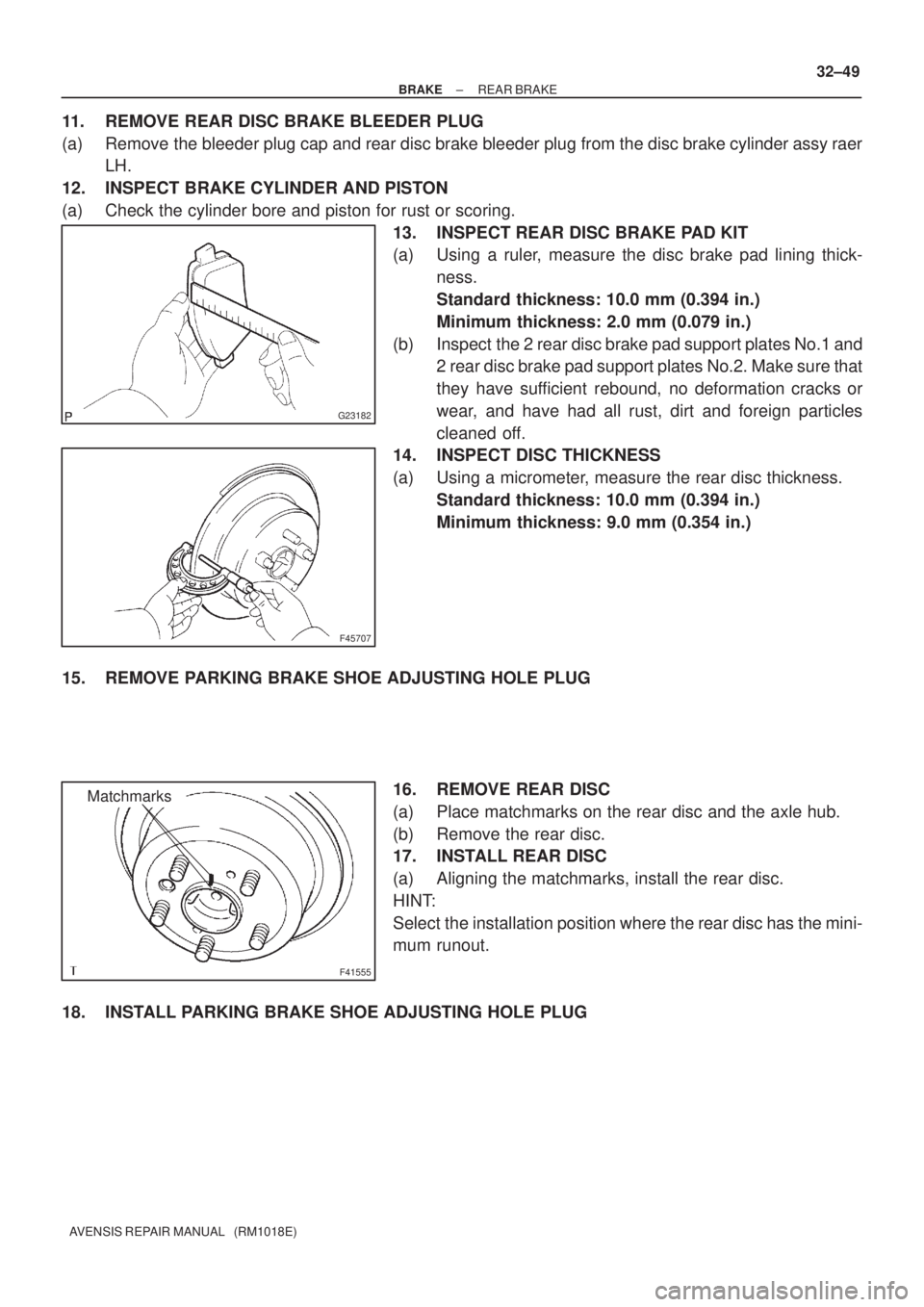
13. INSPECT REAR DISC BRAKE PAD KIT
(a) Using a ruler, measure the disc brake pad lining thick-
ness.
Standard thickness: 10.0 mm (0.394 in.)
Minimum thickness: 2.0 mm (0.079 in.)
(b) Inspect the 2 rear disc brake pad support plates No.1 and
2 rear disc brake pad support plates No.2. Make sure that
they have sufficient rebound, no deformation cracks or
wear, and have had all rust, dirt and foreign particles
cleaned off.
14. INSPECT DISC THICKNESS
(a) Using a micrometer, measure the rear disc thickness.
Standard thickness: 10.0 mm (0.394 in.)
Minimum thickness: 9.0 mm (0.354 in.)
15. REMOVE PARKING BRAKE SHOE ADJUSTING HOLE PLUG
16. REMOVE REAR DISC
(a) Place matchmarks on the rear disc and the axle hub.
(b) Remove the rear disc.
17. INSTALL REAR DISC
(a) Aligning the matchmarks, install the rear disc.
HINT:
Select the installation position where the rear disc has the mini-
mum runout.
18. INSTALL PARKING BRAKE SHOE ADJUSTING HOLE PLUG
Page 2621 of 5135
320GE±03
G23180
� Gasket Flexible Hose
30 (306, 22)
Disc Brake Cylinder
Assy Rear LH
Disc Brake
Pad Kit Rear
� Non±reusable part
N�m (kgf�cm, ft�lbf) : Specified torque
Lithium soap base glycol grease
Rear Disc Brake
Bush Dust Boot
Rear Disc Brake
Pad Support Plate No.1
Rear Disc Brake
Cylinder Mounting LH
RearDisc
Brake Piston
Cylinder Boot � Piston Seal
Rear Disc Brake
Cylinder Slide Pin (No.2) Bleeder Plug Cap
Rear Disc Brake
Bleeder Plug
Rear Disc Brake
Cylinder Slide Bush
Rear Disc Brake
Cylinder Slide Pin (No.1)
Rear Disc Brake
Bush Dust Boot Rear Disc
Parking Brake Shoe
Adjusting Hole Plug
47 (475, 34)
30 (306, 22)
47 (475, 34)
29 (296, 21)
10 (102, 7)
Rear Disc Brake
Pad Support Plate No.2
Union Bolt
�� � Bolt � Bolt
32±46
± BRAKEREAR BRAKE
AVENSIS REPAIR MANUAL (RM1018E)
REAR DISC BRAKE
COMPONENTS
Page 2643 of 5135
400DA±02
������������D30339
Neutral
Basic Line
Groove
Neutral
Basic Line
GrooveU241E:
U341E: 40±8
± AUTOMATIC TRANSMISSION / TRANSPARK/NEUTRAL POSITION SWITCH ASSY (ATM)
AVENSIS REPAIR MANUAL (RM1018E)
ADJUSTMENT
1. INSPECT PARK/NEUTRAL POSITION SWITCH ASSY
(a) Apply the parking brake and turn the ignition switch ON.
(b) Depress the brake pedal and check that the engine starts only when the shift lever is set in N or P posi-
tion and it does not start in other position.
(c) Check that the back±up light is on and the reverse warning buzzer sounds only when the shift lever
is set in R position and these do not function in other position.
If a failure is found, check the park/neutral position switch for continuity.
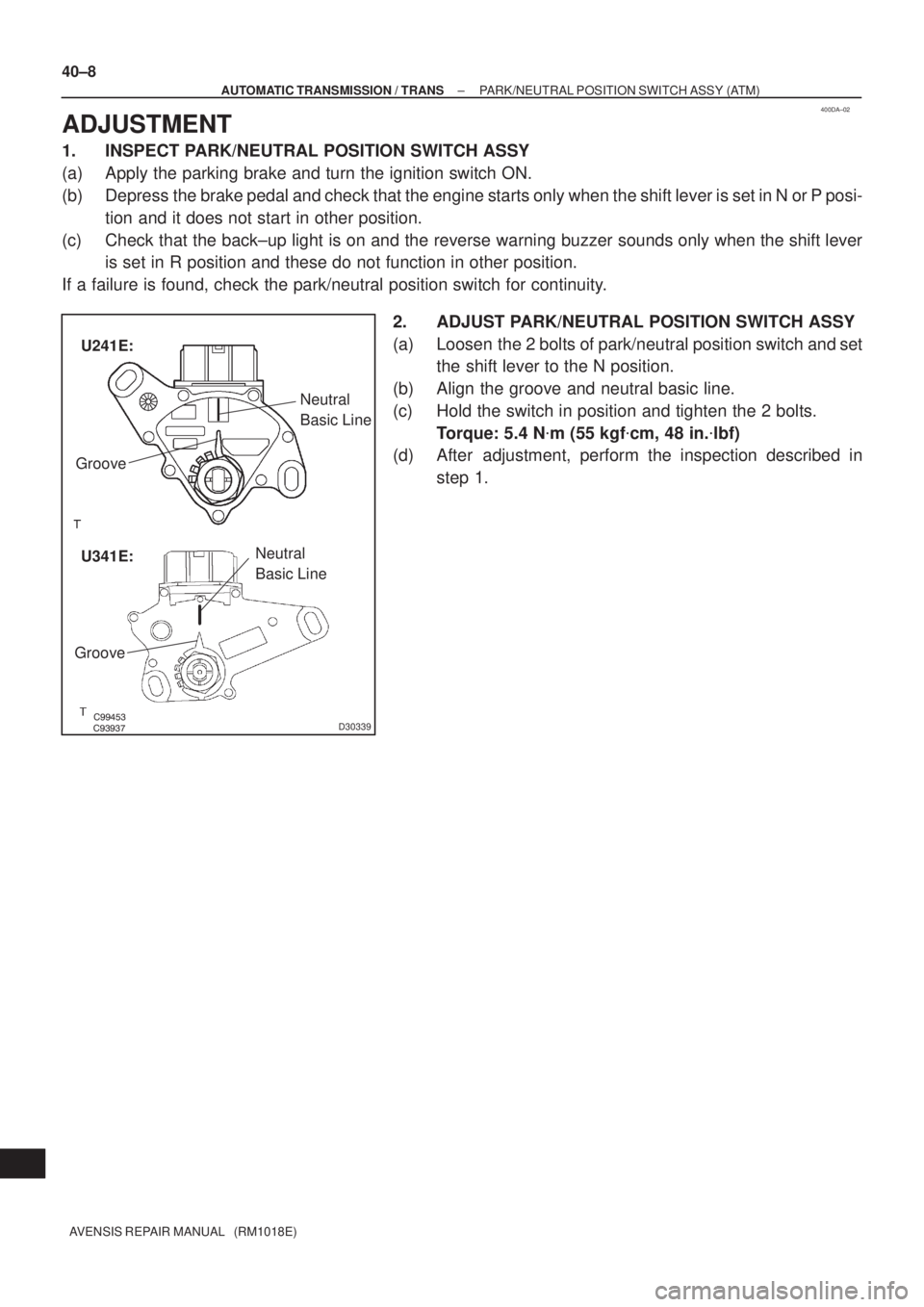
2. ADJUST PARK/NEUTRAL POSITION SWITCH ASSY
(a) Loosen the 2 bolts of park/neutral position switch and set
the shift lever to the N position.
(b) Align the groove and neutral basic line.
(c) Hold the switch in position and tighten the 2 bolts.
Torque: 5.4 N�m (55 kgf�cm, 48 in.�lbf)
(d) After adjustment, perform the inspection described in
step 1.
Page 2649 of 5135
400D7±02
D25120
OK if hot
Add if hot 40±2
± AUTOMATIC TRANSMISSION / TRANSAUTOMATIC TRANSAXLE FLUID (ATM)
AVENSIS REPAIR MANUAL (RM1018E)
AUTOMATIC TRANSAXLE FLUID (ATM)
ON±VEHICLE INSPECTION
1. CHECK THE FLUID LEVEL
HINT:
Drive the vehicle so that the engine and transaxle are at the nor-
mal operating temperature.
Fluid temperature: 70 ± 80 �C (158 ± 176 �F)
(a) Park the vehicle on a level surface and set the parking
brake.
(b) With the engine idling and the brake pedal depressed,
shift the shift lever into all position from P to L position and
return to P position.
(c) Pull out the dipstick and wipe it clean.
(d) Push it back fully into the pipe.
(e) Pull it out and check that the fluid level is in the HOT posi-
tion.
If there are leaks, it is necessary to repair or replace O±rings,
FIPGs, oil seals, plugs or other parts.
Page 2651 of 5135
330C8±01
F45710
Contract
F06409
G22379
������G22380
33±14
±
PARKING BRAKE PARKING BRAKE ASSY
AVENSIS REPAIR MANUAL (RM1018E)
OVERHAUL
HINT:
Overhaul the RH side by the same procedures as those of the LH side.
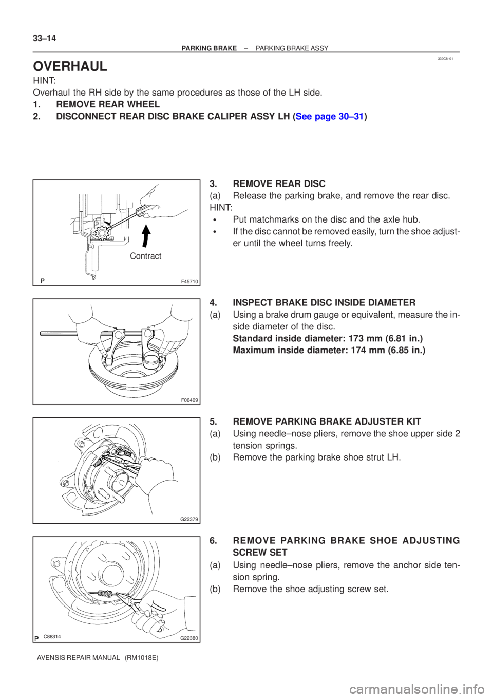
1. REMOVE REAR WHEEL
2.DISCONNECT REAR DISC BRAKE CALIPER ASSY LH (See page 30±31) 3. REMOVE REAR DISC
(a) Release the parking brake, and remove the rear disc.
HINT:
�Put matchmarks on the disc and the axle hub.
�If the disc cannot be removed easily, turn the shoe adjust-
er until the wheel turns freely.
4. INSPECT BRAKE DISC INSIDE DIAMETER
(a) Using a brake drum gauge or equivalent, measure the in- side diameter of the disc.
Standard inside diameter: 173 mm (6.81 in.)
Maximum inside diameter: 174 mm (6.85 in.)
5. REMOVE PARKING BRAKE ADJUSTER KIT
(a) Using needle±nose pliers, remove the shoe upper side 2 tension springs.
(b) Remove the parking brake shoe strut LH.
6. REMOVE PARKING BRAKE SHOE ADJUSTING
SCREW SET
(a) Using needle±nose pliers, remove the anchor side ten- sion spring.
(b) Remove the shoe adjusting screw set.