Page 1183 of 5135

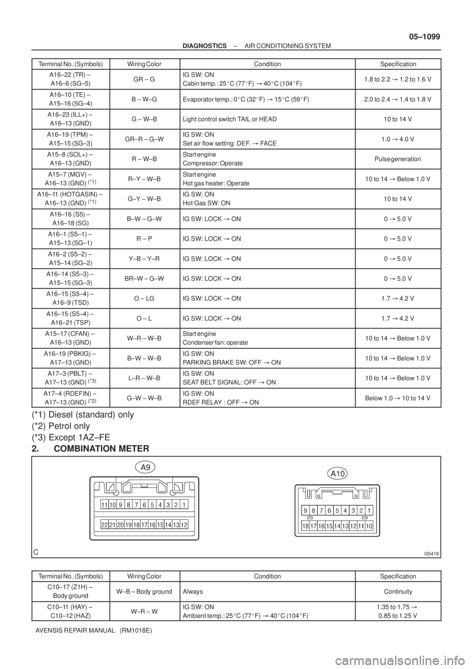
I35419
A10A9
± DIAGNOSTICSAIR CONDITIONING SYSTEM
05±1099
AVENSIS REPAIR MANUAL (RM1018E)Terminal No. (Symbols)Specification Condition Wiring Color
A16±22 (TR) ±
A16±6 (SG±5)GR ± GIG SW: ON
Cabin temp.: 25�C (77�F) � 40�C (104�F)1.8 to 2.2 � 1.2 to 1.6 V
A16±10 (TE) ±
A15±16 (SG±4)B ± W±GEvaporator temp.: 0�C (32�F) � 15�C (59�F)2.0 to 2.4 � 1.4 to 1.8 V
A16±23 (ILL+) ±
A16±13 (GND)G ± W±BLight control switch TAIL or HEAD10 to 14 V
A16±19 (TPM) ±
A15±15 (SG±3)GR±R ± G±WIG SW: ON
Set air flow setting: DEF. � FACE1.0 � 4.0 V
A15±8 (SOL+) ±
A16±13 (GND)R ± W±BStart engine
Compressor: OperatePulse generation
A15±7 (MGV) ±
A16±13 (GND) (*1)R±Y ± W±BStart engine
Hot gas heater: Operate10 to 14 � Below 1.0 V
A16±11 (HOTGASIN) ±
A16±13 (GND) (*1)G±Y ± W±BIG SW: ON
Hot Gas SW: ON10 to 14 V
A16±16 (S5) ±
A16±18 (SG)B±W ± G±WIG SW: LOCK � ON0 � 5.0 V
A16±1 (S5±1) ±
A15±13 (SG±1)R ± PIG SW: LOCK � ON0 � 5.0 V
A16±2 (S5±2) ±
A15±14 (SG±2)Y±B ± Y±RIG SW: LOCK � ON0 � 5.0 V
A16±14 (S5±3) ±
A15±15 (SG±3)BR±W ± G±WIG SW: LOCK � ON0 � 5.0 V
A16±15 (S5±4) ±
A16±9 (TSD)O ± LGIG SW: LOCK � ON1.7 � 4.2 V
A16±15 (S5±4) ±
A16±21 (TSP)O ± LIG SW: LOCK � ON1.7 � 4.2 V
A15±17 (CFAN) ±
A16±13 (GND)W±R ± W±BStart engine
Condenser fan: operate10 to 14 � Below 1.0 V
A16±19 (PBKIG) ±
A17±13 (GND)B±W ± W±BIG SW: ON
PARKING BRAKE SW: OFF � ON10 to 14 � Below 1.0 V
A17±3 (PBLT) ±
A17±13 (GND) (*3)L±R ± W±BIG SW: ON
SEAT BELT SIGNAL: OFF � ON10 to 14 � Below 1.0 V
A17±4 (RDEFIN) ±
A17±13 (GND) (*2)G±W ± W±BIG SW: ON
RDEF RELAY : OFF � ONBelow 1.0 � 10 to 14 V
(*1) Diesel (standard) only
(*2) Petrol only
(*3) Except 1AZ±FE
2. COMBINATION METER
Terminal No. (Symbols)Wiring ColorConditionSpecification
C10±17 (Z1H) ±
Body groundW±B ± Body groundAlwaysContinuity
C10±11 (HAY) ±
C10±12 (HAZ)W±R ± WIG SW: ON
Ambient temp.: 25�C (77�F) � 40�C (104�F)1.35 to 1.75 �
0.85 to 1.25 V
Page 1952 of 5135
A77884
A77885
A77886
A77887
A78450
11±106
± FUELFUEL TANK ASSY (DIESEL)
AVENSIS REPAIR MANUAL (RM1018E)
11. REMOVE PARKING BRAKE CABLE ASSY NO.2
(a) Remove the 2 set bolts of the parking brake cable.
12. REMOVE PARKING BRAKE CABLE ASSY NO.3
(a) Remove the 2 set bolts of the parking brake cable.
13. DISCONNECT BREATHER TUBE FUEL HOSE
(a) Loosen the hose clamp and disconnect the fuel tank
breather hose.
14. DISCONNECT FUEL TANK TO FILLER PIPE HOSE
(a) Loosen the hose clamp and disconnect the fuel tank to fill-
er pipe hose.
15. DISCONNECT FUEL TANK RETURN TUBE
Page 1954 of 5135

A77892
A77893
UpperFuel Tank
Rear
Hose Clamp
A81618
11±108
±
FUEL FUEL TANK ASSY(DIESEL)
AVENSIS REPAIR MANUAL (RM1018E)
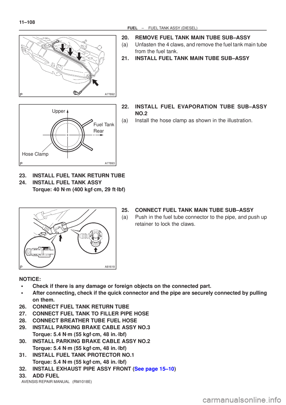
20.REMOVE FUEL TANK MAIN TUBE SUB±ASSY
(a)Unfasten the 4 claws, and remove the fuel tank main tube from the fuel tank.
21.INSTALL FUEL TANK MAIN TUBE SUB±ASSY
22.INSTALL FUEL EVAPOR ATION TUBE SUB±ASSY
NO.2
(a)Install the hose clamp as shown in the illustration.
23.INSTALL FUEL TANK RETURN TUBE
24.INSTALL FUEL TANK ASSY Torque: 40 N �m (400 kgf �cm, 29 ft �lbf)
25.CONNECT FUEL TANK MAIN TUBE SUB±ASSY
(a)Push in the fuel tube connector to the pipe, and push up retainer to lock the claws.
NOTICE:
�Check if there is any damage or foreign objects on the connected part.
�After connecting, check if the quick connector and the pipe are securely\
connected by pulling
on them.
26.CONNECT FUEL TANK RETURN TUBE
27.CONNECT FUEL TANK TO FILLER PIPE HOSE
28.CONNECT BREATHER TUBE FUEL HOSE
29.INSTALL PARKING BRAKE CABLE ASSY NO.3 Torque: 5.4 N �m (55 kgf �cm, 48 in. �lbf)
30.INSTALL PARKING BRAKE CABLE ASSY NO.2 Torque: 5.4 N �m (55 kgf �cm, 48 in. �lbf)
31.INSTALL FUEL TANK PROTECTOR NO.1
Torque: 5.4 N �m (55 kgf �cm, 48 in. �lbf)
32.INSTALL EXHAUST PIPE ASSY FRONT (See page 15±10)
33. ADD FUEL
Page 1958 of 5135
A78268
N´m (kgf´cm, ft´lbf)
: Specified torqueParking Brake Cable
Assy No. 3 Parking Brake Cable
Assy No. 2 Fuel Tank Protector No. 1
Fuel Tank Band Breather Tube Fuel HoseFuel Tank to Filler Pipe Hose
Fuel Tank Band
5.4 (55, 48 in.�lbf)
5.4 (55, 48 in.�lbf)
5.4 (55, 48 in.�lbf)
40 (400, 29)
11±102
± FUELFUEL TANK ASSY (DIESEL)
AVENSIS REPAIR MANUAL (RM1018E)
Page 1962 of 5135
A78519
(a)
(b)
(a)(b)
(a)
(a)
A77883
A77884
± FUELFUEL TANK ASSY (GASOLINE)
11±95
AVENSIS REPAIR MANUAL (RM1018E)
12. REMOVE EXHAUST PIPE ASSY CENTER
(1AZ±FE/1AZ±FSE ENGINE TYPE)
(a) Remove the 4 bolts and 2 compression springs.
(b) Remove the exhaust pipe center and the gasket from the
2 exhaust pipe supports.
(c) Remove the gasket from the exhaust pipe center.
13. REMOVE FUEL TANK PROTECTOR NO.1
(a) Remove the 4 bolts, and then remove the fuel tank pro-
tector.
14. REMOVE PARKING BRAKE CABLE ASSY NO.2
(a) Remove the 2 set bolts of the parking brake cable.
Page 1963 of 5135
A77885
A77886
A77887
A78450
11±96
± FUELFUEL TANK ASSY (GASOLINE)
AVENSIS REPAIR MANUAL (RM1018E)
15. REMOVE PARKING BRAKE CABLE ASSY NO.3
(a) Remove the 2 set bolts of the parking brake cable.
16. DISCONNECT BREATHER TUBE FUEL HOSE
(a) Loosen the hose clamp and disconnect the fuel tank
breather hose.
17. DISCONNECT FUEL TANK TO FILLER PIPE HOSE
(a) Loosen the hose clamp and disconnect the fuel tank to fill-
er pipe hose.
18. DISCONNECT FUEL TANK RETURN TUBE (1AZ±FSE
ENGINE TYPE)
Page 1966 of 5135

A81618
Push
2
1
Retainer
A77857
A78440
New Gasket
A77857
± FUELFUEL TANK ASSY (GASOLINE)
11±99
AVENSIS REPAIR MANUAL (RM1018E)
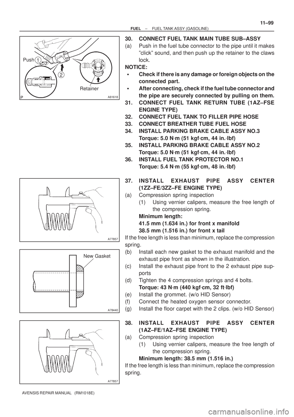
30. CONNECT FUEL TANK MAIN TUBE SUB±ASSY
(a) Push in the fuel tube connector to the pipe until it makes
ºclickº sound, and then push up the retainer to the claws
lock.
NOTICE:
�Check if there is any damage or foreign objects on the
connected part.
�After connecting, check if the fuel tube connector and
the pipe are securely connected by pulling on them.
31. CONNECT FUEL TANK RETURN TUBE (1AZ±FSE
ENGINE TYPE)
32. CONNECT FUEL TANK TO FILLER PIPE HOSE
33. CONNECT BREATHER TUBE FUEL HOSE
34. INSTALL PARKING BRAKE CABLE ASSY NO.3
Torque: 5.0 N�m (51 kgf�cm, 44 in.�lbf)
35. INSTALL PARKING BRAKE CABLE ASSY NO.2
Torque: 5.0 N�m (51 kgf�cm, 44 in.�lbf)
36. INSTALL FUEL TANK PROTECTOR NO.1
Torque: 5.4 N�m (55 kgf�cm, 48 in.�lbf)
37. INSTALL EXHAUST PIPE ASSY CENTER
(1ZZ±FE/3ZZ±FE ENGINE TYPE)
(a) Compression spring inspection
(1) Using vernier calipers, measure the free length of
the compression spring.
Minimum length:
41.5 mm (1.634 in.) for front x manifold
38.5 mm (1.516 in.) for front x tail
If the free length is less than minimum, replace the compression
spring.
(b) Install each new gasket to the exhaust manifold and the
exhaust pipe front as shown in the illustration.
(c) Install the exhaust pipe front to the 2 exhaust pipe sup-
ports
(d) Tighten the 4 compression springs and 4 bolts.
Torque: 43 N�m (440 kgf�cm, 32 ft�lbf)
(e) Install the grommet. (w/o HID Sensor)
(f) Connect the heated oxygen sensor connector.
(g) Install the floor carpet with the 2 clips. (w/o HID Sensor)
38. INSTALL EXHAUST PIPE ASSY CENTER
(1AZ±FE/1AZ±FSE ENGINE TYPE)
(a) Compression spring inspection
(1) Using vernier calipers, measure the free length of
the compression spring.
Minimum length: 38.5 mm (1.516 in.)
If the free length is less than minimum, replace the compression
spring.
Page 1970 of 5135
A77881
Fuel Tank AssyFuel Hose No. 1Fuel Tank
to Filler Pipe Hose
Fuel Tank Band Sub±assy
No. 1
Fuel Tank Band Sub±assy
No. 1 LH
Fuel Tank Protector
No. 1
Parking Brake Cable Assy
No. 2
Parking Brake Cable Assy
No. 3
5.0 (51, 44 in.�lbf)
5.0 (51, 44 in.�lbf)
5.4 (54, 47 in.�lbf)x4
40 (400, 29)
40 (400, 29)
N´m (kgf´cm, ft´lbf) : Specified torque
± FUELFUEL TANK ASSY (GASOLINE)
11±91
AVENSIS REPAIR MANUAL (RM1018E)