Page 2492 of 5135
G25775
G23865
G23866
G23867
G23868
± REAR SUSPENSIONREAR SHOCK ABSORBER WITH COIL SPRING
27±9
AVENSIS REPAIR MANUAL (RM1018E)
14. REMOVE REAR SHOCK ABSORBER WITH COIL
SPRING
(a) Support the rear suspension arm assy No.1 LH.
(b) Remove the bolt and nut from the rear suspension arm
assy No.1 LH.
NOTICE:
When removing the bolt, hold the nut not to rotate.
(c) Remove the 3 nuts.
(d) Remove the 2 bolts, and separate the parking brake cable
assy No.3.
(e) Remove the 3 bolts from the rear suspension arm assy
No.1 LH.
(f) Press the rear suspension arm assy No.1 LH down to the
outside of the vehicle and remove the rear shock absorb-
er with coil spring.
Page 2495 of 5135

G23868
G23867
G25772
G25771
27±12
± REAR SUSPENSIONREAR SHOCK ABSORBER WITH COIL SPRING
AVENSIS REPAIR MANUAL (RM1018E)
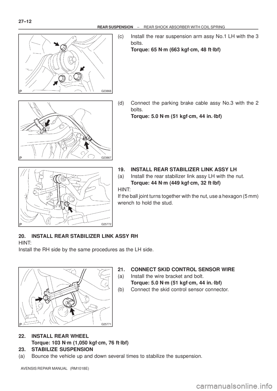
(c) Install the rear suspension arm assy No.1 LH with the 3
bolts.
Torque: 65 N�m (663 kgf�cm, 48 ft�lbf)
(d) Connect the parking brake cable assy No.3 with the 2
bolts.
Torque: 5.0 N�m (51 kgf�cm, 44 in.�lbf)
19. INSTALL REAR STABILIZER LINK ASSY LH
(a) Install the rear stabilizer link assy LH with the nut.
Torque: 44 N�m (449 kgf�cm, 32 ft�lbf)
HINT:
If the ball joint turns together with the nut, use a hexagon (5 mm)
wrench to hold the stud.
20. INSTALL REAR STABILIZER LINK ASSY RH
HINT:
Install the RH side by the same procedures as the LH side.
21. CONNECT SKID CONTROL SENSOR WIRE
(a) Install the wire bracket and bolt.
Torque: 5.0 N�m (51 kgf�cm, 44 in.�lbf)
(b) Connect the skid control sensor connector.
22. INSTALL REAR WHEEL
Torque: 103 N�m (1,050 kgf�cm, 76 ft�lbf)
23. STABILIZE SUSPENSION
(a) Bounce the vehicle up and down several times to stabilize the suspension.
Page 2501 of 5135

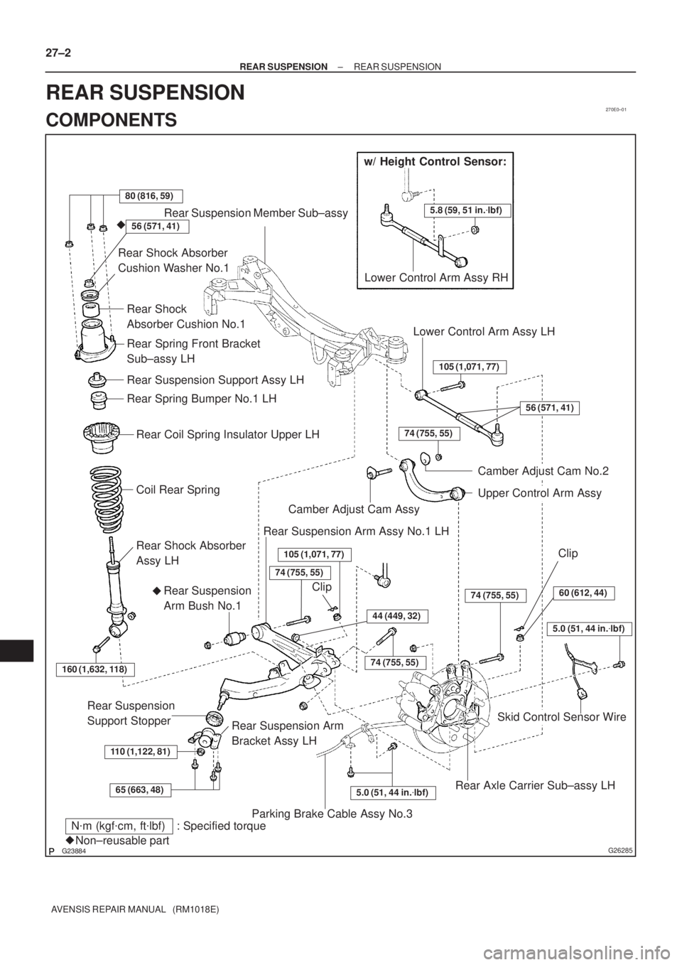
270E0±01
������G26285
w/ Height Control Sensor:
5.8 (59, 51 in.�lbf)
80 (816, 59)
Rear Suspension Member Sub±assy
Rear Shock Absorber
Cushion Washer No.1
Coil Rear Spring
Rear Coil Spring Insulator Upper LH
Rear Spring Bumper No.1 LH
Rear Suspension Support Assy LH
Rear Spring Front Bracket
Sub±assy LH
Rear Shock
Absorber Cushion No.1
Lower Control Arm Assy RH
Rear Shock Absorber
Assy LH
160 (1,632, 118)
110 (1,122, 81)
65 (663, 48)
Rear Suspension
Support Stopper
Rear Suspension Arm
Bracket Assy LH
Rear Suspension
Arm Bush No.1�Camber Adjust Cam Assy
Rear Suspension Arm Assy No.1 LH
74 (755, 55)
105 (1,071, 77)
44 (449, 32)
74 (755, 55)
74 (755, 55)
Parking Brake Cable Assy No.3
5.0 (51, 44 in.�lbf)Rear Axle Carrier Sub±assy LH
Skid Control Sensor Wire
74 (755, 55)
Upper Control Arm Assy
Camber Adjust Cam No.2
Lower Control Arm Assy LH
105 (1,071, 77)
5.0 (51, 44 in.�lbf)
60 (612, 44)
N�m (kgf�cm, ft�lbf) : Specified torque
Non±reusable part �
56 (571, 41)
�56 (571, 41)
Clip
Clip 27±2
± REAR SUSPENSIONREAR SUSPENSION
AVENSIS REPAIR MANUAL (RM1018E)
REAR SUSPENSION
COMPONENTS
Page 2565 of 5135
270E3±01
G23867
G25771
G25772
G25775
±
REAR SUSPENSION REAR SUSPENSION ARM ASSY NO.1 LH
27±15
AVENSIS REPAIR MANUAL (RM1018E)
REAR SUSPENSION ARM ASSY NO.1 LH
OVERHAUL
HINT:
COMPONENTS: See page 27±2.
1. REMOVE REAR WHEEL
2. SEPARATE PARKING BRAKE CABLE ASSY NO.3
(a) Remove the 2 bolts, and separate the parking brake cableassy No.3.
3. DISCONNECT SKID CONTROL SENSOR WIRE
(a) Disconnect the skid control sensor connector.
(b) Remove the bolt and wire bracket.
4. SEPARATE REAR STABILIZER LINK ASSY LH
(a) Remove the nut, and separate the rear stabilizer link assy LH.
HINT:
If the ball joint turns together with the nut, use a hexagon (5 mm)
wrench to hold the stud.
5. REMOVE LOWER CONTROL ARM ASSY LH
(a) Support the rear suspension arm assy No.1 LH.
Page 2571 of 5135
G23871
G23872
G25772
G25771
G23867
± REAR SUSPENSIONREAR SUSPENSION ARM ASSY NO.1 LH
27±21
AVENSIS REPAIR MANUAL (RM1018E)
10. INSTALL LOWER CONTROL ARM ASSY LH
(a) Install the lower control arm assy LH, and temporarily
tighten the bolt.
(b) Install the lower control arm assy LH to the rear axle carri-
er LH, and temporarily tighten the nut.
11. INSTALL REAR STABILIZER LINK ASSY LH
(a) Install the rear stabilizer link assy LH with the nut.
Torque: 44 N�m (449 kgf�cm, 32 ft�lbf)
HINT:
If the ball joint turns together with the nut, use a hexagon (5
mm) wrench to hold the stud.
12. CONNECT SKID CONTROL SENSOR WIRE
(a) Install the wire bracket and bolt.
Torque: 5.0 N�m (51 kgf�cm, 44 in.�lbf)
(b) Connect the skid control sensor connector.
13. INSTALL PARKING BRAKE CABLE ASSY NO.3
(a) Connect the parking brake cable assy No.3 with the 2
bolts.
Torque: 5.0 N�m (51 kgf�cm, 44 in.�lbf)
Page 2592 of 5135
G23176
Pedal Free Play
R00934
Pedal Reserve
Distance
± BRAKEBRAKE PEDAL SUB±ASSY
32±7
AVENSIS REPAIR MANUAL (RM1018E)
(h) Check the protrusion of the rod.
Protrusion of the rod: 0.5 to 2.6 mm (0.020 to 0.102 in.)
(i) Install the clevis pin and clip.
(j) After adjusting the pedal height, check the pedal free
play.
2. CHECK PEDAL FREE PLAY
(a) Stop the engine and depress the brake pedal several
times until there is no more vacuum left in the booster.
(b) Push in the pedal until the beginning of the resistance is
felt. Measure the distance, as shown.
Pedal free play: 1 to 6 mm (0.04 to 0.24 in.)
3. CHECK PEDAL RESERVE DISTANCE
(a) Release the parking brake lever.
With the engine running, depress the pedal and measure
the pedal reserve distance, as shown.
Pedal reserve distance from asphalt sheet at 490 N
(50 kgf, 110.2 lbf): More than 50 mm (1.97 in.)
If the distance is out of the specification , troubleshoot the brake
system.
Page 2595 of 5135

3201B±12
32±2
±
BRAKE BRAKE SYSTEM
AVENSIS REPAIR MANUAL (RM1018E)
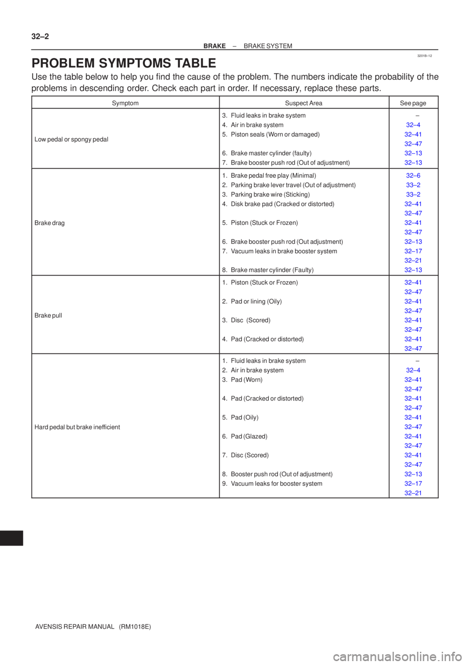
PROBLEM SYMPTOMS TABLE
Use the table below to help you find the cause of the problem. The numbers \
indicate the probability of the
problems in descending order. Check each part in order. If necessary, replace these parts.
SymptomSuspect AreaSee page
Low pedal or spongy pedal
3. Fluid leaks in brake system
4. Air in brake system
5. Piston seals (Worn or damaged)
6. Brake master cylinder (faulty)
7. Brake booster push rod (Out of adjustment) ±
32±4
32±41
32±47
32±13
32±13
Brake drag
1. Brake pedal free play (Minimal)
2. Parking brake lever travel (Out of adjustment)
3. Parking brake wire (Sticking)
4. Disk brake pad (Cracked or distorted)
5. Piston (Stuck or Frozen)
6. Brake booster push rod (Out adjustment)
7. Vacuum leaks in brake booster system
8. Brake master cylinder (Faulty)32±6
33±2
33±2
32±41
32±47
32±41
32±47
32±13
32±17
32±21
32±13
Brake pull
1. Piston (Stuck or Frozen)
2. Pad or lining (Oily)
3. Disc (Scored)
4. Pad (Cracked or distorted) 32±41
32±47
32±41
32±47
32±41
32±47
32±41
32±47
Hard pedal but brake inefficient
1. Fluid leaks in brake system
2. Air in brake system
3. Pad (Worn)
4. Pad (Cracked or distorted)
5. Pad (Oily)
6. Pad (Glazed)
7. Disc (Scored)
8. Booster push rod (Out of adjustment)
9. Vacuum leaks for booster system ±
32±4
32±41
32±47
32±41
32±47
32±41
32±47
32±41
32±47
32±41
32±47
32±13
32±17
32±21
Page 2599 of 5135

300JZ±01
������F45267
F44818
������F45752
SST
±
DRIVE SHAFT / PROPELLER SHAFT REAR AXLE CARRIER SUB±ASSY LH
30±31
AVENSIS REPAIR MANUAL (RM1018E)
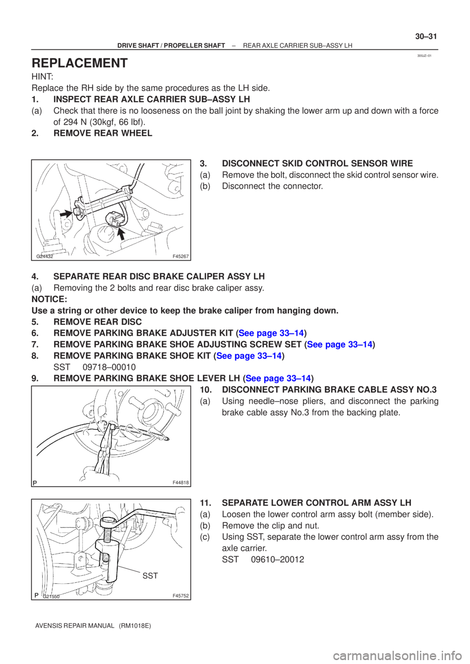
REPLACEMENT
HINT:
Replace the RH side by the same procedures as the LH side.
1. INSPECT REAR AXLE CARRIER SUB±ASSY LH
(a) Check that there is no looseness on the ball joint by shaking the lower arm up and down with a force
of 294 N (30kgf, 66 lbf).
2. REMOVE REAR WHEEL
3. DISCONNECT SKID CONTROL SENSOR WIRE
(a) Remove the bolt, disconnect the skid control sensor wire.
(b) Disconnect the connector.
4. SEPARATE REAR DISC BRAKE CALIPER ASSY LH
(a) Removing the 2 bolts and rear disc brake caliper assy.
NOTICE:
Use a string or other device to keep the brake caliper from hanging down\
.
5. REMOVE REAR DISC
6.REMOVE PARKING BRAKE ADJUSTER KIT (See page 33±14)
7.REMOVE PARKING BRAKE SHOE ADJUSTING SCREW SET (See page 33±14)
8.REMOVE PARKING BRAKE SHOE KIT (See page 33±14) SST 09718±00010
9.REMOVE PARKING BRAKE SHOE LEVER LH (See page 33±14)
10. DISCONNECT PARKING BRAKE CABLE ASSY NO.3
(a) Using needle±nose pliers, and disconnect the parkingbrake cable assy No.3 from the backing plate.
11. SEPARATE LOWER CONTROL ARM ASSY LH
(a) Loosen the lower control arm assy bolt (member side).
(b) Remove the clip and nut.
(c) Using SST, separate the lower control arm assy from the axle carrier.
SST 09610±20012