Page 2668 of 5135
3300F±07
F44808
Lock NutAdjusting Nut
33±2
±
PARKING BRAKE PARKING BRAKE SYSTEM
AVENSIS REPAIR MANUAL (RM1018E)
ADJUSTMENT
1. REMOVE REAR WHEEL
2.ADJUST PARKING BRAKE SHOE CLEARANCE (See page 33±14)
3. INSTALL REAR WHEEL Torque: 103 N �m (1,050 kgf �cm, 76 ft �lbf)
4. INSPECT PARKING BRAKE LEVER TRAVEL
(a) Pull the parking brake lever all the way up, and count the number of cli\
cks. Parking brake lever travel: 6 ± 9 clicks at 196 N (20 kgf, 44.1 lbf)\
5. ADJUST PARKING BRAKE LEVER TRAVEL
(a) Remove the console box assy RR.(See page71±11)
(b) Loosen the lock nut and turn the adjusting nut until the le- ver travel turns correct.
(c) Tighten the lock nut. Torque: 5.0 N �m (51 kgf �cm, 44 in. �lbf)
(d) Install the console box assy RR.
(See page 71±11)
Page 2669 of 5135
3300E±07
±
PARKING BRAKE PARKING BRAKE SYSTEM
33±1
AVENSIS REPAIR MANUAL (RM1018E)
PARKING BRAKE SYSTEM
PROBLEM SYMPTOMS TABLE
Use the table below to help you find the cause of the problem. The numbers \
indicate the likelihood of the
cause in the descending order. Check each parts in the order shown. Replace these parts as necessary.
SymptomSuspect AreaSee page
Brake drag
1. Parking brake lever travel (Out of adjustment)
2. Parking brake wire (Sticking)
3. Parking brake shoe clearance (Out of adjustment)
4. Parking brake shoe lining (Cracked or distorted)
5. Tension or return spring (Damaged)33±2
33±7
33±10
33±14
33±14
33±14
Page 2768 of 5135

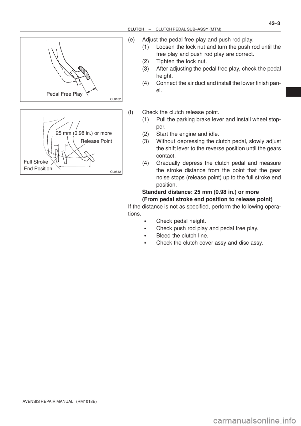
CL0102Pedal Free Play
CL0512
25 mm (0.98 in.) or more
Release Point
Full Stroke
End Position
± CLUTCHCLUTCH PEDAL SUB±ASSY (MTM)
42±3
AVENSIS REPAIR MANUAL (RM1018E)
(e) Adjust the pedal free play and push rod play.
(1) Loosen the lock nut and turn the push rod until the
free play and push rod play are correct.
(2) Tighten the lock nut.
(3) After adjusting the pedal free play, check the pedal
height.
(4) Connect the air duct and install the lower finish pan-
el.
(f) Check the clutch release point.
(1) Pull the parking brake lever and install wheel stop-
per.
(2) Start the engine and idle.
(3) Without depressing the clutch pedal, slowly adjust
the shift lever to the reverse position until the gears
contact.
(4) Gradually depress the clutch pedal and measure
the stroke distance from the point that the gear
noise stops (release point) up to the full stroke end
position.
Standard distance: 25 mm (0.98 in.) or more
(From pedal stroke end position to release point)
If the distance is not as specified, perform the following opera-
tions.
�Check pedal height.
�Check push rod play and pedal free play.
�Bleed the clutch line.
�Check the clutch cover assy and disc assy.
Page 2839 of 5135

± HEATER & AIR CONDITIONERAIR CONDITIONING SYSTEM
55±5
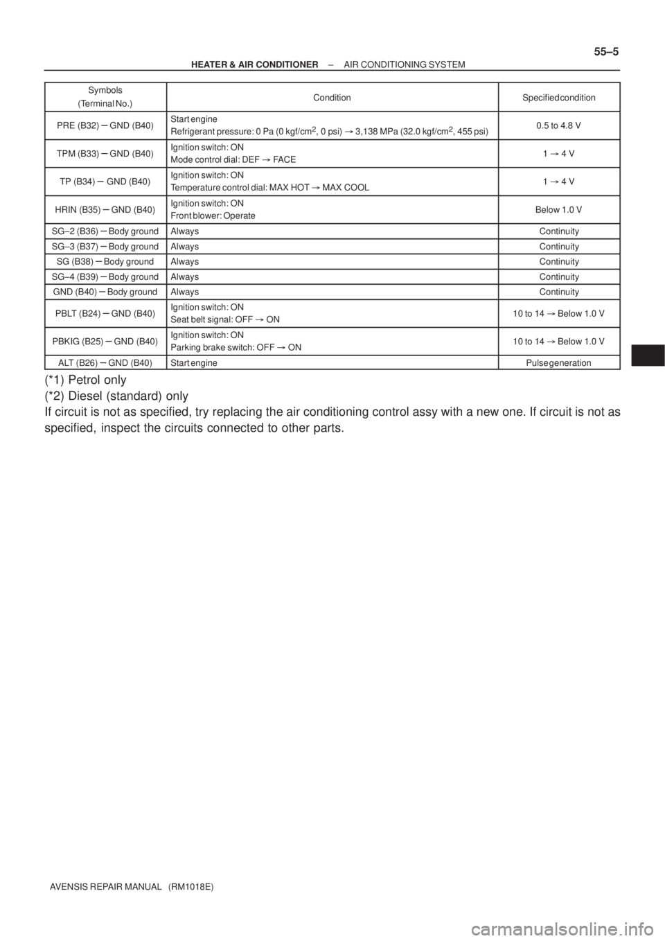
AVENSIS REPAIR MANUAL (RM1018E)Symbols
(Terminal No.)Specified condition Condition
PRE (B32) ± GND (B40)Start engine
Refrigerant pressure: 0 Pa (0 kgf/cm2, 0 psi) � 3,138 MPa (32.0 kgf/cm2, 455 psi)0.5 to 4.8 V
TPM (B33) ± GND (B40)Ignition switch: ON
Mode control dial: DEF � FACE1 � 4 V
TP (B34) ± GND (B40)Ignition switch: ON
Temperature control dial: MAX HOT � MAX COOL1 � 4 V
HRIN (B35) ± GND (B40)Ignition switch: ON
Front blower: OperateBelow 1.0 V
SG±2 (B36) ± Body groundAlwaysContinuity
SG±3 (B37) ± Body groundAlwaysContinuity
SG (B38) ± Body groundAlwaysContinuity
SG±4 (B39) ± Body groundAlwaysContinuity
GND (B40) ± Body groundAlwaysContinuity
PBLT (B24) ± GND (B40)Ignition switch: ON
Seat belt signal: OFF � ON10 to 14 � Below 1.0 V
PBKIG (B25) ± GND (B40)Ignition switch: ON
Parking brake switch: OFF � ON10 to 14 � Below 1.0 V
ALT (B26) ± GND (B40)Start enginePulse generation
(*1) Petrol only
(*2) Diesel (standard) only
If circuit is not as specified, try replacing the air conditioning control assy with a new one. If circuit is not as
specified, inspect the circuits connected to other parts.
Page 3237 of 5135

IG
SPEED
BKL SW
(D±seat)
BKL SW
(P seat)
WRN LAMP
BUZZERON
OFF
15km/h
0
BELT ON
BELT OFF
LVL1
LVL2 BELT ON
BELT OFF
ON
OFF OFF
30s
90s30s
90s
± INSTRUMENT PANEL/METERCOMBINATION METER
71±5
AVENSIS REPAIR MANUAL (RM1018E)
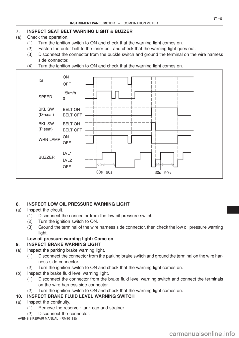
7. INSPECT SEAT BELT WARNING LIGHT & BUZZER
(a) Check the operation.
(1) Turn the ignition switch to ON and check that the warning light comes on.
(2) Fasten the outer belt to the inner belt and check that the warning light goes out.
(3) Disconnect the connector from the buckle switch and ground the terminal on the wire harness
side connector.
(4) Turn the ignition switch to ON and check that the warning light comes on.
8. INSPECT LOW OIL PRESSURE WARNING LIGHT
(a) Inspect the circuit.
(1) Disconnect the connector from the low oil pressure switch.
(2) Turn the ignition switch to ON.
(3) Ground the terminal of the wire harness side connector, then check the low oil pressure warning
light.
Low oil pressure warning light: Come on
9. INSPECT BRAKE WARNING LIGHT
(a) Inspect the parking brake warning light.
(1) Disconnect the connector from the parking brake switch and ground the terminal on the wire har-
ness side connector.
(2) Turn the ignition switch to ON and check that the warning light comes on.
(b) Inspect the brake fluid level warning light.
(1) Disconnect the connector from the brake fluid level warning switch and connect the terminals
on the wire harness side connector.
(2) Turn the ignition switch to ON and check that the warning light comes on.
10. INSPECT BRAKE FLUID LEVEL WARNING SWITCH
(a) Inspect the continuity.
(1) Remove the reservoir tank cap and strainer.
(2) Disconnect the connector.
Page 3465 of 5135

01±10
± INTRODUCTIONTERMS
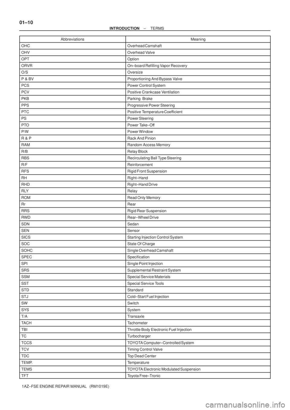
1AZ±FSE ENGINE REPAIR MANUAL (RM1019E)Abbreviations Meaning
OHCOverhead Camshaft
OHVOverhead Valve
OPTOption
ORVROn±board Refilling Vapor Recovery
O/SOversize
P & BVProportioning And Bypass Valve
PCSPower Control System
PCVPositive Crankcase Ventilation
PKBParking Brake
PPSProgressive Power Steering
PTCPositive Temperature Coefficient
PSPower Steering
PTOPower Take±Off
P/WPower Window
R & PRack And Pinion
RAMRandom Access Memory
R/BRelay Block
RBSRecirculating Ball Type Steering
R/FReinforcement
RFSRigid Front Suspension
RHRight±Hand
RHDRight±Hand Drive
RLYRelay
ROMRead Only Memory
RrRear
RRSRigid Rear Suspension
RWDRear±Wheel Drive
SDNSedan
SENSensor
SICSStarting Injection Control System
SOCState Of Charge
SOHCSingle Overhead Camshaft
SPECSpecification
SPISingle Point Injection
SRSSupplemental Restraint System
SSMSpecial Service Materials
SSTSpecial Service Tools
STDStandard
STJCold±Start Fuel Injection
SWSwitch
SYSSystem
T/ATransaxle
TACHTachometer
TBIThrottle Body Electronic Fuel Injection
TCTurbocharger
TCCSTOYOTA Computer±Controlled System
TCVTiming Control Valve
TDCTop Dead Center
TEMP.Temperature
TEMSTOYOTA Electronic Modulated Suspension
TFTToyota Free±Tronic
Page 3988 of 5135
05±840
± DIAGNOSTICSABS WITH EBD & BA & TRC & VSC SYSTEM
AVENSIS REPAIR MANUAL (RM1018E)
BRAKE WARNING LIGHT CIRCUIT
CIRCUIT DESCRIPTION
The Brake warning light comes on when the brake fluid is insufficient, the parking brake is applied or the EBD
is defective.
0543H±04
Page 3990 of 5135
05±842
±
DIAGNOSTICS ABS WITH EBD & BA & TRC & VSC SYSTEM
AVENSIS REPAIR MANUAL (RM1018E)
INSPECTION PROCEDURE
HINT:
Start the inspection from step 1 if you are using the hand±held tester and\
start from step 2 if you are not using
the hand±held tester.
1PERFORM ACTIVE TEST BY HAND±HELD TESTER(BRAKE WARNING LIGHT)
(a)Check that ºONº and ºOFFº of the Brake warning light is shown on \
the combination meter by the hand± held tester.
OKGo to step 4
NG
2CHECK DTC FOR ABS
(a)Check the DTC on page 05±756. YES REPAIR CIRCUIT INDICATED BY OUTPUTCODE
NO
3 INSPECT BRAKE WARNING LIGHT
(a)See combination meter troubleshooting on page 71±1. NG REPAIR OR REPLACE COMBINATION METERASSEMBLY
OK
4INSPECT PARKING BRAKE SWITCH ASSY(See page 71±3)
NG REPLACE PARKING BRAKE SWITCH ASSY
OK
5INSPECT BRAKE FLUID LEVEL WARNING SWITCH(See page 71±3)
NG REPLACE BRAKE MASTER CYLINDER RESERVOIR SUB±ASSY
OK