Page 480 of 5135

A00309
V1
Manifold Absolute Pressure Sensor
18
E13ECM
5V
E1 1R±W
33
G±W
2 3
BR28
E2 PIM VC
VOUT
GNDE13
E13 VCC
± DIAGNOSTICSSFI SYSTEM (1AZ±FSE)
05±343
AVENSIS REPAIR MANUAL (RM1018E)
WIRING DIAGRAM
INSPECTION PROCEDURE
HINT:
�If different DTCs related to different systems that have terminal E2 as the ground terminal are output
simultaneously, terminal E2 may be open.
�Read freeze frame data using the hand±held tester. Freeze frame data records the engine conditions
when a malfunction is detected. When troubleshooting, it is useful for determining whether the vehicle
was running or stopped, the engine was warmed up or not, the air±fuel ratio was lean or rich, etc. at
the time of the malfunction.
1 READ VALUE OF HAND±HELD TESTER(INTAKE MANIFOLD ABSOLUTE
PRESSURE)
(a) Connect the hand±held tester to the DLC3.
(b) Turn the ignition switch ON.
(c) Push the hand±held tester main switch ON.
(d) Select the item ºDIAGNOSIS / OBD/MOBD / DATA LIST / ALL / MAPº and read its value displayed on
the hand±held tester.
Pressure: Same as the atmospheric pressure
Result:
Manifold Absolute Pressure (kPa)Proceed to
142 or moreA
0.0B
OK (Same as present pressure) (*1)C
*1: The value must be changed when the engine is run or stopped.
B Go to step 3
C CHECK FOR INTERMITTENT PROBLEMS
A
Page 501 of 5135
A71007
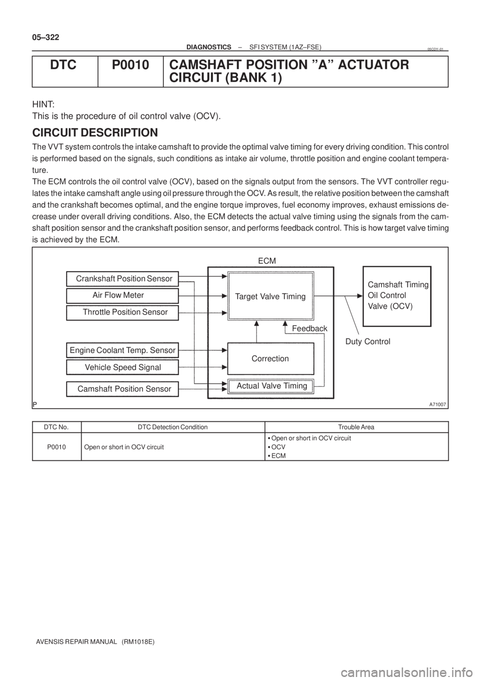
Air Flow Meter Crankshaft Position Sensor
Actual Valve TimingCorrection Target Valve Timing
Feedback
Duty Control ECM
Camshaft Timing
Oil Control
Valve (OCV)
Vehicle Speed Signal Engine Coolant Temp. SensorThrottle Position Sensor
Camshaft Position Sensor
05±322
± DIAGNOSTICSSFI SYSTEM (1AZ±FSE)
AVENSIS REPAIR MANUAL (RM1018E)
DTC P0010 CAMSHAFT POSITION ºAº ACTUATOR
CIRCUIT (BANK 1)
HINT:
This is the procedure of oil control valve (OCV).
CIRCUIT DESCRIPTION
The VVT system controls the intake camshaft to provide the optimal valve timing for every driving condition. This control
is performed based on the signals, such conditions as intake air volume, throttle position and engine coolant tempera-
ture.
The ECM controls the oil control valve (OCV), based on the signals output from the sensors. The VVT controller regu-
lates the intake camshaft angle using oil pressure through the OCV. As result, the relative position between the camshaft
and the crankshaft becomes optimal, and the engine torque improves, fuel economy improves, exhaust emissions de-
crease under overall driving conditions. Also, the ECM detects the actual valve timing using the signals from the cam-
shaft position sensor and the crankshaft position sensor, and performs feedback control. This is how target valve timing
is achieved by the ECM.
DTC No.DTC Detection ConditionTrouble Area
P0010Open or short in OCV circuit
�Open or short in OCV circuit
�OCV
�ECM
05CDY±01
Page 515 of 5135
± DIAGNOSTICSSFI SYSTEM (1AZ±FSE)
05±415
AVENSIS REPAIR MANUAL (RM1018E)
DTC P0200 INJECTOR CIRCUIT / OPEN
DTC P0201 INJECTOR CIRCUIT / OPEN ± (CYLINDER 1)
DTC P0202 INJECTOR CIRCUIT / OPEN ± (CYLINDER 2)
DTC P0203 INJECTOR CIRCUIT / OPEN ± (CYLINDER 3)
DTC P0204 INJECTOR CIRCUIT / OPEN ± (CYLINDER 4)
CIRCUIT DESCRIPTION
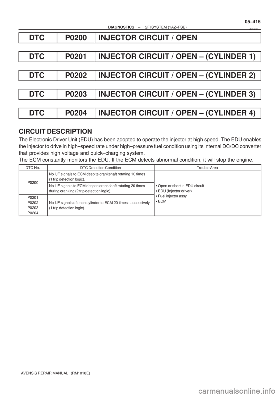
The Electronic Driver Unit (EDU) has been adopted to operate the injector at high speed. The EDU enables
the injector to drive in high±speed rate under high±pressure fuel condition using its internal DC/DC converter
that provides high voltage and quick±charging system.
The ECM constantly monitors the EDU. If the ECM detects abnormal condition, it will stop the engine.
DTC No.DTC Detection ConditionTrouble Area
P0200
No IJF signals to ECM despite crankshaft rotating 10 times
(1 trip detection logic).
P0200No IJF signals to ECM despite crankshaft rotating 20 times
during cranking (2 trip detection logic).�Open or short in EDU circuit
�EDU (Injector driver)
P0201
P0202
P0203
P0204
No IJF signals of each cylinder to ECM 20 times successively
(1 trip detection logic).
(j )
�Fuel injector assy
�ECM
05CKG±01
Page 520 of 5135
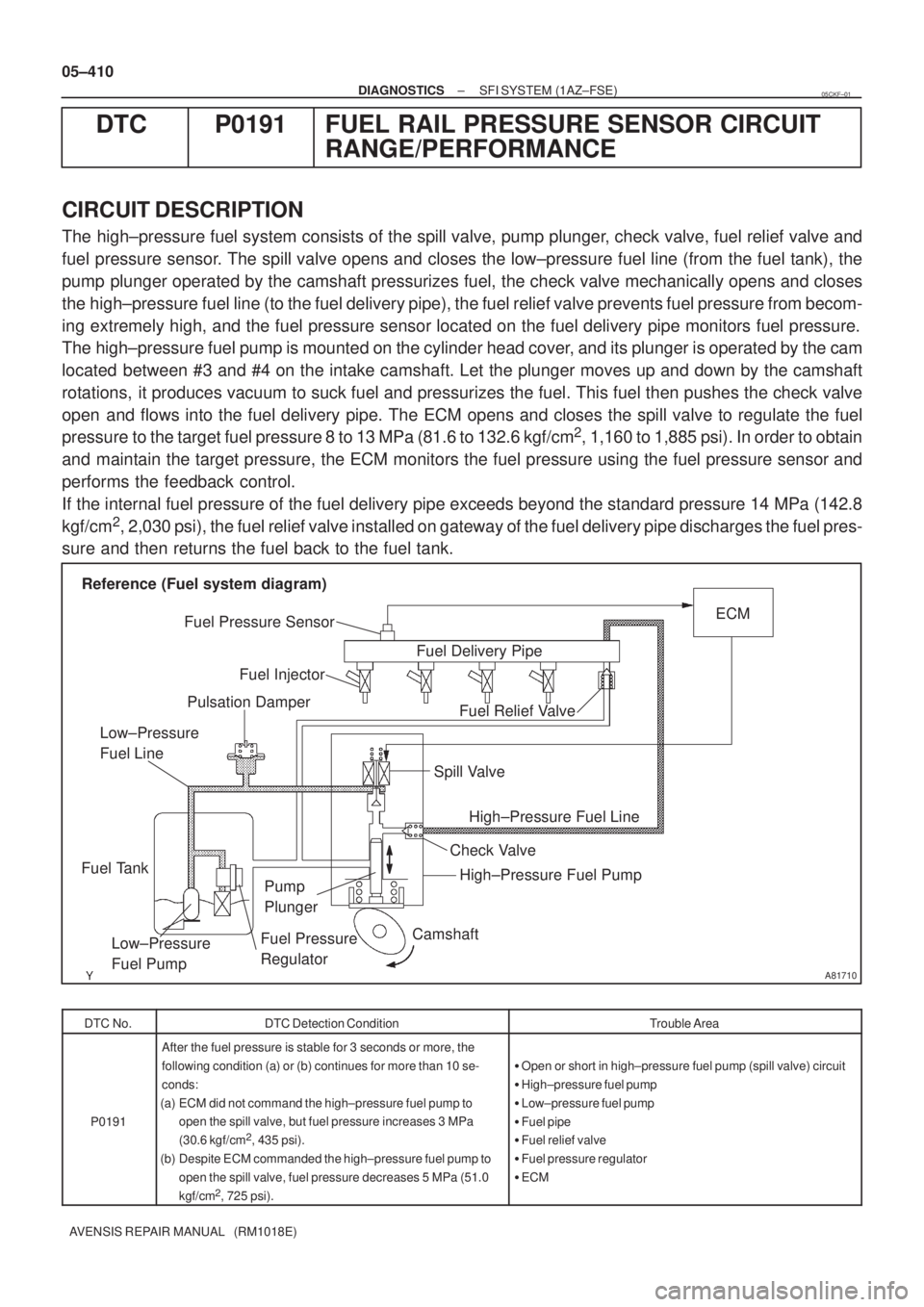
A81710
Camshaft
Fuel Relief ValveECM
Fuel Pressure Sensor
Pulsation Damper
Fuel Tank
Fuel Pressure
Regulator Fuel Injector
Spill Valve
High±Pressure Fuel Pump
Low±Pressure
Fuel PumpFuel Delivery Pipe Reference (Fuel system diagram)
Pump
Plunger
High±Pressure Fuel Line Low±Pressure
Fuel Line
Check Valve
05±410
± DIAGNOSTICSSFI SYSTEM (1AZ±FSE)
AVENSIS REPAIR MANUAL (RM1018E)
DTC P0191 FUEL RAIL PRESSURE SENSOR CIRCUIT
RANGE/PERFORMANCE
CIRCUIT DESCRIPTION
The high±pressure fuel system consists of the spill valve, pump plunger, check valve, fuel relief valve and
fuel pressure sensor. The spill valve opens and closes the low±pressure fuel line (from the fuel tank), the
pump plunger operated by the camshaft pressurizes fuel, the check valve mechanically opens and closes
the high±pressure fuel line (to the fuel delivery pipe), the fuel relief valve prevents fuel pressure from becom-
ing extremely high, and the fuel pressure sensor located on the fuel delivery pipe monitors fuel pressure.
The high±pressure fuel pump is mounted on the cylinder head cover, and its plunger is operated by the cam
located between #3 and #4 on the intake camshaft. Let the plunger moves up and down by the camshaft
rotations, it produces vacuum to suck fuel and pressurizes the fuel. This fuel then pushes the check valve
open and flows into the fuel delivery pipe. The ECM opens and closes the spill valve to regulate the fuel
pressure to the target fuel pressure 8 to 13 MPa (81.6 to 132.6 kgf/cm
2, 1,160 to 1,885 psi). In order to obtain
and maintain the target pressure, the ECM monitors the fuel pressure using the fuel pressure sensor and
performs the feedback control.
If the internal fuel pressure of the fuel delivery pipe exceeds beyond the standard pressure 14 MPa (142.8
kgf/cm
2, 2,030 psi), the fuel relief valve installed on gateway of the fuel delivery pipe discharges the fuel pres-
sure and then returns the fuel back to the fuel tank.
DTC No.DTC Detection ConditionTrouble Area
P0191
After the fuel pressure is stable for 3 seconds or more, the
following condition (a) or (b) continues for more than 10 se-
conds:
(a) ECM did not command the high±pressure fuel pump to
open the spill valve, but fuel pressure increases 3 MPa
(30.6 kgf/cm
2, 435 psi).
(b) Despite ECM commanded the high±pressure fuel pump to
open the spill valve, fuel pressure decreases 5 MPa (51.0
kgf/cm
2, 725 psi).
�Open or short in high±pressure fuel pump (spill valve) circuit
�High±pressure fuel pump
�Low±pressure fuel pump
�Fuel pipe
�Fuel relief valve
�Fuel pressure regulator
�ECM
05CKF±01
Page 521 of 5135
±
DIAGNOSTICS SFI SYSTEM(1AZ±FSE)
05±411
AVENSIS REPAIR MANUAL (RM1018E)
WIRING DIAGRAM
Refer to DTC P1235 on page 05±477.
INSPECTION PROCEDURE
HINT:
�If different DTCs related to different systems that have terminal E2 as the ground terminal are output
simultaneously, terminal E2 may be open.
�Read freeze frame data using the hand±held tester. Freeze frame data records the engine conditions
when a malfunction is detected. When troubleshooting, it is useful for deter\
mining whether the vehicle
was running or stopped, the engine was warmed up or not, the air±fuel ra\
tio was lean or rich, etc. at
the time of the malfunction.
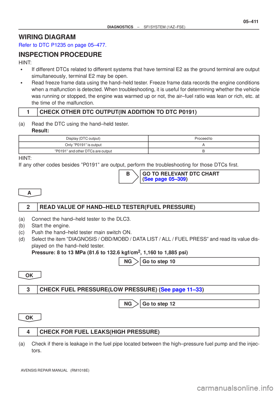
1CHECK OTHER DTC OUTPUT(IN ADDITION TO DTC P0191)
(a)Read the DTC using the hand±held tester.
Result:
Display (DTC output)Proceed to
Only ºP0191º is outputA
ºP0191º and other DTCs are outputB
HINT:
If any other codes besides ºP0191º are output, perform the troublesh\
ooting for those DTCs first.
BGO TO RELEVANT DTC CHART(See page 05±309)
A
2READ VALUE OF HAND±HELD TESTER(FUEL PRESSURE)
(a)Connect the hand±held tester to the DLC3.
(b)Start the engine.
(c)Push the hand±held tester main switch ON.
(d)Select the item ºDIAGNOSIS / OBD/MOBD / DATA LIST / ALL / FUEL PRESSº and read its value dis- played on the hand±held tester.
Pressure: 8 to 13 MPa (81.6 to 132.6 kgf/cm
2, 1,160 to 1,885 psi)
NGGo to step 10
OK
3CHECK FUEL PRESSURE(LOW PRESSURE) (See page 11±33)
NG Go to step 12
OK
4 CHECK FOR FUEL LEAKS(HIGH PRESSURE)
(a) Check if there is leakage in the fuel pipe located between the high±pressure fuel pump and the injec- tors.
Page 522 of 5135
������B12608
A81695
E12
ECM Connector FP+FP±
A81702
S3
High±Pressure Fuel Pump
(Spill Valve) Connector Wire Harness Side
05±412
± DIAGNOSTICSSFI SYSTEM (1AZ±FSE)
AVENSIS REPAIR MANUAL (RM1018E)
NG REPAIR OR REPLACE A PLACE FUEL LEAKS
OK
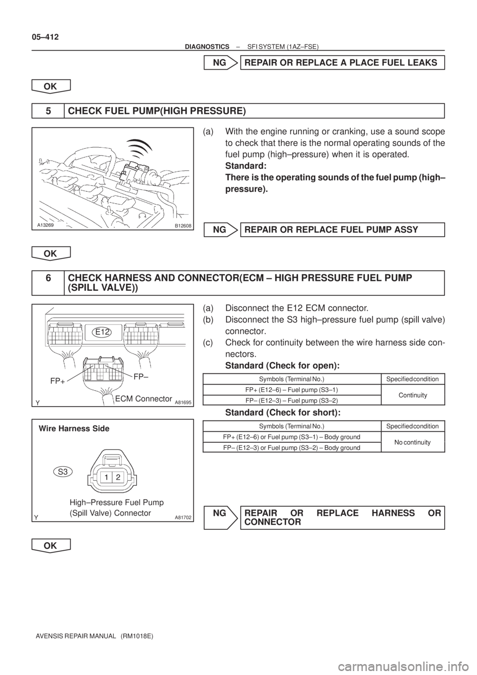
5 CHECK FUEL PUMP(HIGH PRESSURE)
(a) With the engine running or cranking, use a sound scope
to check that there is the normal operating sounds of the
fuel pump (high±pressure) when it is operated.
Standard:
There is the operating sounds of the fuel pump (high±
pressure).
NG REPAIR OR REPLACE FUEL PUMP ASSY
OK
6 CHECK HARNESS AND CONNECTOR(ECM ± HIGH PRESSURE FUEL PUMP
(SPILL VALVE))
(a) Disconnect the E12 ECM connector.
(b) Disconnect the S3 high±pressure fuel pump (spill valve)
connector.
(c) Check for continuity between the wire harness side con-
nectors.
Standard (Check for open):
Symbols (Terminal No.)Specified condition
FP+ (E12±6) ± Fuel pump (S3±1)ContinuityFP± (E12±3) ± Fuel pump (S3±2)Continuity
Standard (Check for short):
Symbols (Terminal No.)Specified condition
FP+ (E12±6) or Fuel pump (S3±1) ± Body groundNo continuityFP± (E12±3) or Fuel pump (S3±2) ± Body groundNo continuity
NG REPAIR OR REPLACE HARNESS OR
CONNECTOR
OK
Page 523 of 5135
±
DIAGNOSTICS SFI SYSTEM(1AZ±FSE)
05±413
AVENSIS REPAIR MANUAL (RM1018E)
7CHECK IF DTC OUTPUTS REOCCUR(DTC P0191 IS OUTPUT AGAIN)
(a)Clear the DTC (See page 05±294).
(b)Warm up the engine.
(c)Let the engine idle for 30 seconds or more.
(d)Read the DTC (See page 05±294).
Result:
Display (DTC output)Proceed to
ºP0191º is output againA
No DTC outputB
BCHECK FOR INTERMITTENT PROBLEMS
A
8REPLACE FUEL RELIEF VALVE ASSY
GO
9CHECK IF DTC OUTPUTS REOCCUR(DTC P0191 IS OUTPUT AGAIN)
(a)Clear the DTC (See page 05±294).
(b)Warm up the engine.
(c)Let the engine idle for 30 seconds or more.
(d)Read the DTC (See page 05±294). Result:
Display (DTC output)Proceed to
ºP0191º is output againA
No DTC outputB
BSYSTEM OK
A
REPLACE FUEL PUMP ASSY (HIGH PRESSURE)
10CHECK OPERATION OF FUEL PUMP(LOW PRESSURE) (See page 11±33)
OK Go to step 3
NG
11CHECK VOLTAGE FUEL PUMP(LOW PRESSURE) (See page 05±507)
OK Go to step 3
NG
CHECK FOR FUEL PUMP CONTROL CIRCUIT (See page 05±507)
Page 524 of 5135
05±414
± DIAGNOSTICSSFI SYSTEM (1AZ±FSE)
AVENSIS REPAIR MANUAL (RM1018E)
12 CHECK FOR FUEL LEAKS(LOW PRESSURE)
(a) Check if there is leakage in the fuel pipe located between the fuel tank and the high±pressure fuel
pump.
NG REPAIR OR REPLACE A PLACE FUEL LEAKS
OK
REPLACE FUEL PRESSURE REGULATOR ASSY