Page 3597 of 5135
![TOYOTA AVENSIS 2005 Service Repair Manual C81320
C81321
C81322
40±74
± AUTOMATIC TRANSMISSION / TRANSFRONNT DIFFERENTIAL ASSY (U34#E Series)
U340E A/T REPAIR MANUAL (RM824E)
10. INSTALL FRONT DIFFERENTIAL SIDE GEAR
[ 41331F / 4301 ]
(a) A](/manual-img/14/57441/w960_57441-3596.png "TOYOTA AVENSIS 2005 Service Repair Manual C81320
C81321
C81322
40±74
± AUTOMATIC TRANSMISSION / TRANSFRONNT DIFFERENTIAL ASSY (U34#E Series)
U340E A/T REPAIR MANUAL (RM824E)
10. INSTALL FRONT DIFFERENTIAL SIDE GEAR
[ 41331F / 4301 ]
(a) A")
C81320
C81321
C81322
40±74
± AUTOMATIC TRANSMISSION / TRANSFRONNT DIFFERENTIAL ASSY (U34#E Series)
U340E A/T REPAIR MANUAL (RM824E)
10. INSTALL FRONT DIFFERENTIAL SIDE GEAR
[ 41331F / 4301 ]
(a) After applying ATF to the 2 front differential side gears, 2
side gear thrust washers No. 1, 2 front differential pinions
and 2 pinion thrust washers, install them to the front differ-
ential case.
HINT:
At the time of installation, set the alignment of the front differen-
tial pinions perpendicular to that of the side gear and rotate
them so that their holes will be aligned with the holes in the dif-
ferential case.
11. INSTALL FRONT DIFFERENTIAL PINION SHAFT NO.1
[ 41342F / 4301 ]
(a) Install the pinion shaft so as to align the lock pin holes on
the pinion shaft and differential case.
12. INSPECT BACKLASH
(a) Measure the side gear backlash while holding 1 pinion
gear toward the case.
Standard backlash:
0.05 ± 0.20 mm (0.0020 ± 0.0079 in.)
If the backlash is out of specification, install the correct thrust
washer to the side gear.
(b) Referring to the table below, select thrust washers which
will ensure that the backlash is within for both sides.
Thrust washer thickness: mm (in.)
ThicknessThickness
0.95 (0.0374)1.10 (0.0433)
1.00 (0.0394)1.15 (0.0453)
1.05 (0.0413)1.20 (0.0472)
If the backlash is not within the specification, install a thrust
washer of a different thickness.
Page 3598 of 5135
C81323
C81324
D25177
C81325
���
C81326
± AUTOMATIC TRANSMISSION / TRANSFRONNT DIFFERENTIAL ASSY (U34#E Series)
40±75
U340E A/T REPAIR MANUAL (RM824E)
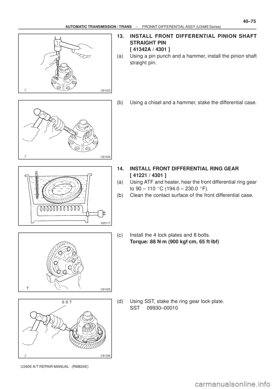
13. INSTALL FRONT DIFFERENTIAL PINION SHAFT
STRAIGHT PIN
[ 41342A / 4301 ]
(a) Using a pin punch and a hammer, install the pinion shaft
straight pin.
(b) Using a chisel and a hammer, stake the differential case.
14. INSTALL FRONT DIFFERENTIAL RING GEAR
[ 41221 / 4301 ]
(a) Using ATF and heater, hear the front differential ring gear
to 90 ± 110 �C (194.0 ± 230.0 �F).
(b) Clean the contact surface of the front differential case.
(c) Install the 4 lock plates and 8 bolts.
Torque: 88 N�m (900 kgf�cm, 65 ft�lbf)
(d) Using SST, stake the ring gear lock plate.
SST 09930±00010
Page 3599 of 5135
D25171
40±76
± AUTOMATIC TRANSMISSION / TRANSFRONNT DIFFERENTIAL ASSY (U34#E Series)
U340E A/T REPAIR MANUAL (RM824E)
15. INSTALL SPEEDOMETER DRIVE (ATM) GEAR
[ 33481X / 4301 ]
(a) Install the speedometer drive gear to the differential case.
Page 3600 of 5135
4002M±01
C67905
C67904
C82123
C67908
± AUTOMATIC TRANSMISSION / TRANSTRANSMISSION VALVE BODY ASSY (U34#E Series)
40±67
U340E A/T REPAIR MANUAL (RM824E)
TRANSMISSION VALVE BODY ASSY (U34#E Series)
OVERHAUL
1. REMOVE LINE PRESSURE CONTROL SOLENOID
ASSY
[ 35290A / 3512 ]
(a) Remove the bolt, and pull out the line pressure control so-
lenoid assy.
2. REMOVE TRANSMISSION 3WAY SOLENOID ASSY
NO.3
[ 35250A / 3512 ]
(a) Remove the bolt, and pull out the transmission 3 way so-
lenoid assy No. 3.
3. REMOVE LOCK UP CONTROL SOLENOID ASSY
[ 35280 / 3512 ]
(a) Remove the bolt, and pull out the lock up control solenoid
assy.
4. REMOVE TRANSMISSION 3WAY SOLENOID ASSY
NO.2
[ 35230 / 3512 ]
(a) Remove the bolt, and pull out the transmission 3 way so-
lenoid assy No. 2.
Page 3601 of 5135
C67907
C67910
C67910
C67907
C67908
40±68
± AUTOMATIC TRANSMISSION / TRANSTRANSMISSION VALVE BODY ASSY (U34#E Series)
U340E A/T REPAIR MANUAL (RM824E)
5. REMOVE AUTOMATIC TRANSMISSION 3WAY
SOLENOID ASSY
[ 35240 / 3512 ]
(a) Remove the bolt, and pull out the automatic transmission
3 way solenoid assy.
6. REMOVE MANUAL VALVE
[ 35418 / 3512 ]
(a) Remove the manual valve from the valve body assy.
7. INSTALL MANUAL VALVE
[ 35418 / 3512 ]
(a) Coat the manual valve with ATF and install it to the valve
body assy.
8. INSTALL AUTOMATIC TRANSMISSION 3WAY
SOLENOID ASSY
[ 35240 / 3512 ]
(a) Install the automatic transmission 3 way solenoid assy
with the bolt.
Torque: 11 N�m (110 kgf�cm, 8 ft�lbf)
9. INSTALL TRANSMISSION 3WAY SOLENOID ASSY
NO.2
[ 35230 / 3512 ]
(a) Install the transmission 3 way solenoid assy No. 2 with the
bolt.
Torque: 11 N�m (110 kgf�cm, 8 ft�lbf)
Page 3602 of 5135

40±69
U340E A/T REPAIR MANUAL (RM824E)
10. INSTALL LOCK UP CONTROL SO")
C82123
C67904
C67905
D25170
A
C
BA
A DB
�
�
C62687
± AUTOMATIC TRANSMISSION / TRANSTRANSMISSION VALVE BODY ASSY (U34#E Series)
40±69
U340E A/T REPAIR MANUAL (RM824E)
10. INSTALL LOCK UP CONTROL SOLENOID ASSY
[ 35280 / 3512 ]
(a) Install the lock up control solenoid assy with the bolt.
Torque: 11 N�m (110 kgf�cm, 8 ft�lbf)
11. INSTALL TRANSMISSION 3WAY SOLENOID ASSY
NO.3
[ 35250A / 3512 ]
(a) Install the transmission 3 way solenoid assy No. 3 with the
bolt.
Torque: 11 N�m (110 kgf�cm, 8 ft�lbf)
12. INSTALL LINE PRESSURE CONTROL SOLENOID
ASSY
[ 35290A / 3512 ]
(a) Install the line pressure control solenoid assy with the
bolt.
Torque: 11 N�m (110 kgf�cm, 8 ft�lbf)
13. TIGHTEN BOLT
(a) Install the valve body assembly and 13 bolts.
Torque: 11 N�m (110 kgf�cm, 8 ft�lbf)
Bolt length:
Bolt A: 32 mm (1.26 in.)
Bolt B: 22 mm (0.87 in.)
Bolt C: 55 mm (2.17 in.)
Bolt D: 45 mm (1.77 in.)
(b) Install the detente spring, detente spring cover and 2
bolts.
Torque: 11 N�m (110 kgf�cm, 8 ft�lbf)
Bolt length:
Bolt A: 14 mm (0.55 in.)
Bolt B: 45 mm (1.77 in.)
(c) Check that the manual valve lever is touching the center
of the detente spring tip roller.
Page 3603 of 5135
�
�
� ��
�
C67914
C67911
40±70
± AUTOMATIC TRANSMISSION / TRANSTRANSMISSION VALVE BODY ASSY (U34#E Series)
U340E A/T REPAIR MANUAL (RM824E)
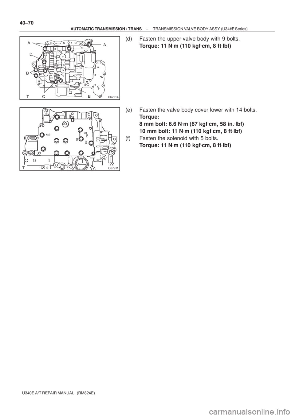
(d) Fasten the upper valve body with 9 bolts.
Torque: 11 N�m (110 kgf�cm, 8 ft�lbf)
(e) Fasten the valve body cover lower with 14 bolts.
Torque:
8 mm bolt: 6.6 N�m (67 kgf�cm, 58 in.�lbf)
10 mm bolt: 11 N�m (110 kgf�cm, 8 ft�lbf)
(f) Fasten the solenoid with 5 bolts.
Torque: 11 N�m (110 kgf�cm, 8 ft�lbf)
Page 3604 of 5135

U340E A/T REPAIR MANUAL (RM824E)
TRANSAXLE REAR COVER ASSY (U34#E Series)
OVERH")
4002L±01
C67881
D08358
C59838
C67883
40±64
± AUTOMATIC TRANSMISSION / TRANSTRANSAXLE REAR COVER ASSY (U34#E Series)
U340E A/T REPAIR MANUAL (RM824E)
TRANSAXLE REAR COVER ASSY (U34#E Series)
OVERHAUL
1. REMOVE TRANSAXLE REAR COVER PLUG
[ 35102B / 3503 ]
(a) Remove the 4 transaxle rear cover plug from the trans-
axle rear cover.
(b) Using a screwdriver, remove the O±ring from the trans-
axle rear cover plug.
2. REMOVE OVERDRIVE BRAKE RETURN SPRING
SUB±ASSY
[ 34603B / 3509 ]
(a) Using SST, a press and a screwdriver, remove the snap
ring.
SST 09387±00070
NOTICE:
Stop the press when the O/D brake piston is lowered 1 ± 2
mm (0.039 ± 0.078 in.) from the snap ring groove, prevent-
ing the O/D brake piston from being deformed.
(b) Remove the O/D brake return spring.
3. INSPECT OVERDRIVE BRAKE RETURN SPRING
SUB±ASSY
[ 34603B / 3509 ]
(a) Using a vernier calipers, measure the free length of the
spring together with the spring seat.
Standard free length: 17.88mm (0.7039 in.)
4. REMOVE 2ND COAST & OVERDRIVE BRAKE PISTON
[ 34622B / 3509 ]
(a) Apply compressed air (392 kPa, 4.0 kgf�cm
2, 57 psi) to the
transaxle rear cover to remove the O/D brake piston.
NOTICE:
�Blowing off the air may cause the piston's jump±out.
When removing the piston, holding it with your hand
using a waste cloth.
�Take care not to splash ATF when air±blowing.
![TOYOTA AVENSIS 2005 Service Repair Manual D25171
40±76
± AUTOMATIC TRANSMISSION / TRANSFRONNT DIFFERENTIAL ASSY (U34#E Series)
U340E A/T REPAIR MANUAL (RM824E)
15. INSTALL SPEEDOMETER DRIVE (ATM) GEAR
[ 33481X / 4301 ]
(a) Install the spe](/manual-img/14/57441/w960_57441-3598.png "TOYOTA AVENSIS 2005 Service Repair Manual D25171
40±76
± AUTOMATIC TRANSMISSION / TRANSFRONNT DIFFERENTIAL ASSY (U34#E Series)
U340E A/T REPAIR MANUAL (RM824E)
15. INSTALL SPEEDOMETER DRIVE (ATM) GEAR
[ 33481X / 4301 ]
(a) Install the spe")

40±67
U340E A/T REPAIR MANUAL (RM824E)
TRANSMISSION VALVE BODY ASSY (U34#E Series)")

U340E A/T REPAIR MANUAL (RM824E)
5. REMOVE AUTOMATIC TRANSMISSION 3WAY
SOLENOID")