Page 3573 of 5135
90�11 0�
C58905
C80408
Match
marks
C67982
41±70
± MANUAL TRANSMISSION/TRANSAXLEDIFFERENTIAL CASE ASSY (C250)
C250 M/T REPAIR MANUAL (RM1020E)
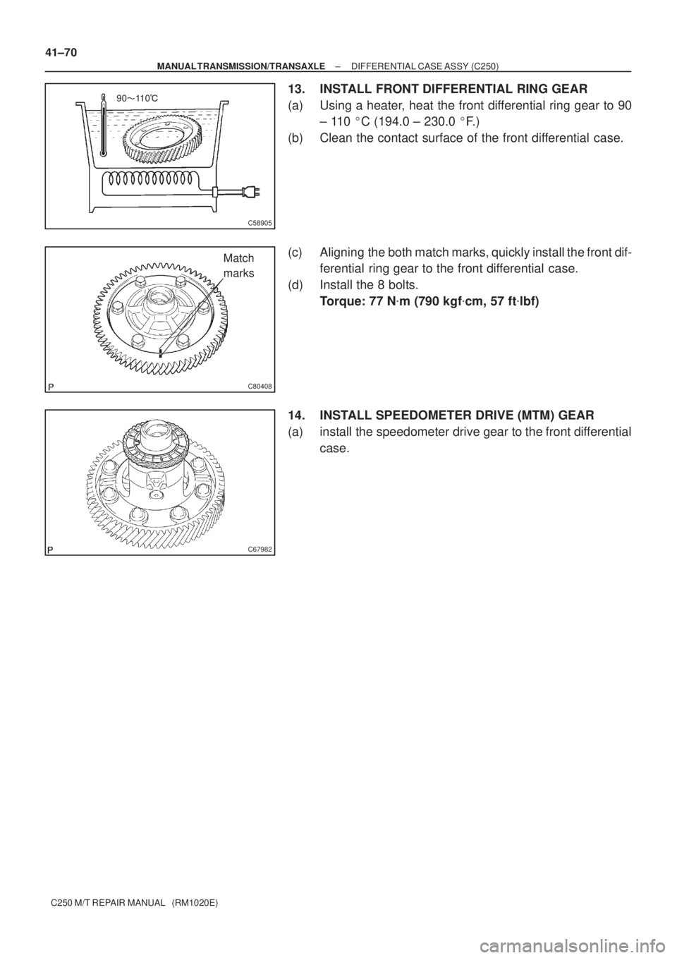
13. INSTALL FRONT DIFFERENTIAL RING GEAR
(a) Using a heater, heat the front differential ring gear to 90
± 110 �C (194.0 ± 230.0 �F. )
(b) Clean the contact surface of the front differential case.
(c) Aligning the both match marks, quickly install the front dif-
ferential ring gear to the front differential case.
(d) Install the 8 bolts.
Torque: 77 N�m (790 kgf�cm, 57 ft�lbf)
14. INSTALL SPEEDOMETER DRIVE (MTM) GEAR
(a) install the speedometer drive gear to the front differential
case.
Page 3574 of 5135
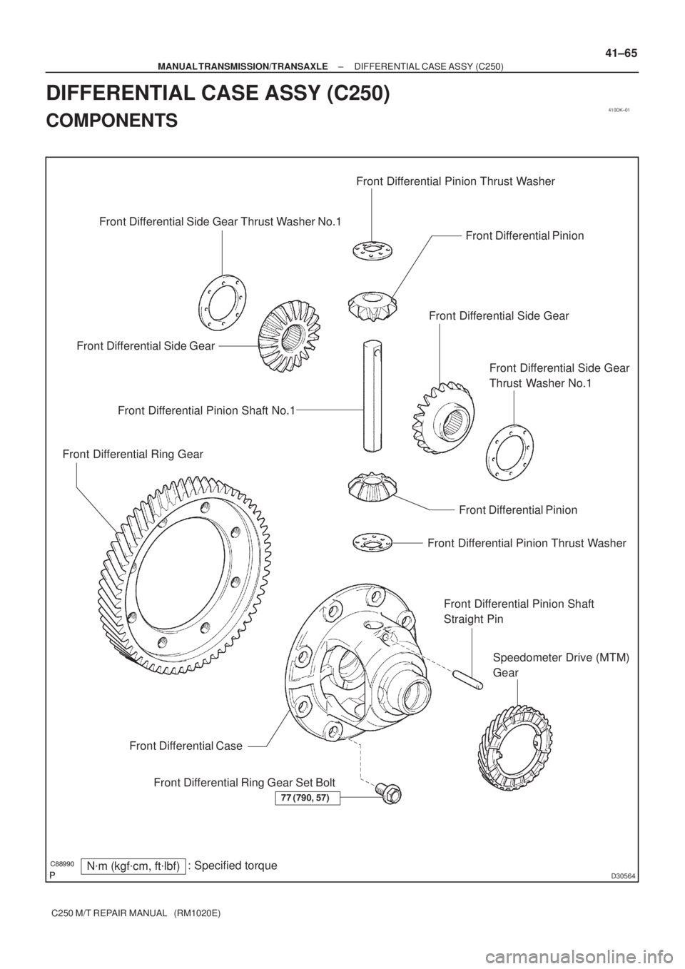
410DK±01
������
D30564
Front Differential Pinion Front Differential Pinion Thrust Washer
N�m (kgf�cm, ft�lbf): Specified torque
77 (790, 57)
Front Differential Ring Gear Set Bolt Front Differential CaseFront Differential Side Gear
Front Differential Side Gear
Thrust Washer No.1
Front Differential Pinion
Front Differential Pinion Thrust Washer
Front Differential Pinion Shaft
Straight Pin Front Differential Side GearFront Differential Side Gear Thrust Washer No.1
Speedometer Drive (MTM)
Gear Front Differential Ring GearFront Differential Pinion Shaft No.1
± MANUAL TRANSMISSION/TRANSAXLEDIFFERENTIAL CASE ASSY (C250)
41±65
C250 M/T REPAIR MANUAL (RM1020E)
DIFFERENTIAL CASE ASSY (C250)
COMPONENTS
Page 3575 of 5135
410DJ±01
C80760
C80761
C80762
C80763
41±60
± MANUAL TRANSMISSION/TRANSAXLESHIFT & SELECT LEVER SHAFT ASSY (C250)
C250 M/T REPAIR MANUAL (RM1020E)
OVERHAUL
1. REMOVE SHIFT & SELECT LEVER BUSH
(a) Remove the shift & select lever bush from the selecting
bell crank assy.
2. REMOVE SELECTING BELLCRANK DUST COVER
NO.1
(a) Remove the selecting bellcrank dust cover No.1 from the
selecting bellcrank assy.
3. REMOVE SELECTING BELL CRANK NO.2
(a) Remove the nut, spring washer and selecting bellcrank
No.2 plate washer.
(b) Remove selecting bellcrank No.2 from the selecting bell-
crank support.
4. REMOVE SELECTING BELLCRANK DUST COVER
NO.2
(a) Remove the selecting bellcrank dust cover No.2 from the
selecting bellcrank No.2.
Page 3576 of 5135

41±61
C250 M/T REPAIR MANUAL (RM1020E)
5. REMOVE SELECTING BELLCRANK NO.2 BUSH
(a) Rem")
C80764
Bush
C80572
D30553
D30554
D30555
± MANUAL TRANSMISSION/TRANSAXLESHIFT & SELECT LEVER SHAFT ASSY (C250)
41±61
C250 M/T REPAIR MANUAL (RM1020E)
5. REMOVE SELECTING BELLCRANK NO.2 BUSH
(a) Remove the 2 selecting bellcrank No.2 bushes from the
selecting bellcrank.
6. REMOVE SELECT SPRING SEAT NO.2
(a) Using a screwdriver, remove the select spring seat No.2
E±ring, select spring seat No.2 and select return spring
No.2 from the shift & select lever shaft.
7. REMOVE SHIFT LEVER INNER NO.2
(a) Using a pin punch (�5mm) and hammer, remove the shift
inner lever slotted pin and shift lever inner No.2 from the
shift & select lever shaft.
HINT:
Make sure of the orientation of the shift lever inner No.2.
8. REMOVE SHIFT LEVER INNER NO.1
(a) Using a pin punch (�5mm) and hammer, remove the shift
inner lever slotted pin, shift lever inner No.1 and shift inter
lock plate from the shift & select lever shaft.
HINT:
Make sure of the orientation of the shift lever inner No.1.
9. REMOVE SELECT INNER LEVER
(a) Using a pin punch (�5mm) and hammer, remove the se-
lect inner lever slotted pin, select inner lever select return
spring No.1 and select return spring No.1 seat from shift
& select lever shaft.
HINT:
Make sure of the orientation of the select inner lever.
Page 3577 of 5135

C250 M/T REPAIR MANUAL (RM1020E)
10. REMOVE SELECT SPRING NO.1 SEAT SHAFT SNAP
RING
(a)")
D30556
C80778
C94255
SST
D30557
41±62
± MANUAL TRANSMISSION/TRANSAXLESHIFT & SELECT LEVER SHAFT ASSY (C250)
C250 M/T REPAIR MANUAL (RM1020E)
10. REMOVE SELECT SPRING NO.1 SEAT SHAFT SNAP
RING
(a) Using 2 screwdrivers and a hammer, remove the select
spring No.1 seat shaft snap ring.
NOTICE:
Do not damage the shaft.
11. REMOVE SHIFT & SELECT LEVER SHAFT DUST BOOT
(a) Remove the shift & select lever shaft dust boot from the shift & select lever shaft.
12. REMOVE CONTROL SHAFT COVER OIL SEAL
(a) Using a screwdriver remove the control shaft cover oil
seal from the control shaft cover.
13. INSTALL CONTROL SHAFT COVER OIL SEAL
(a) Using SST and a hammer, install the new control shaft
cover oil seal to the control shaft cover.
SST 09950±60010 (09951±00220), 09950±70010
(09951±07100)
Drive in depth:
0.2 ± 1.2 mm (0.079 ± 0.0472 in.)
(b) Coat the control shaft cover oil seal with MP grease.
14. INSTALL SHIFT & SELECT LEVER SHAFT DUST
BOOT
(a) Coat the shift & select lever shaft dust boot with MP
grease.
(b) Install the shift & select lever shaft dust boot to the shift
& select lever shaft.
HINT:
Install the boot with the projection up and the hole side down.
Page 3578 of 5135

41±63
C250 M/T REPAIR MANUAL (RM1020E)
15. INSTALL SELECT SPRING NO.1 SEAT SHAFT SNAP
RING")
D30558
D30559
D30560
D30561
C80584
± MANUAL TRANSMISSION/TRANSAXLESHIFT & SELECT LEVER SHAFT ASSY (C250)
41±63
C250 M/T REPAIR MANUAL (RM1020E)
15. INSTALL SELECT SPRING NO.1 SEAT SHAFT SNAP
RING
(a) Coat the shift & select lever shaft with MP grease, install
it and snap ring with a brass bar and hammer.
16. INSTALL SELECT INNER LEVER
(a) Coat the select spring No.1 seat with MP grease.
(b) Using a pin punch (�5mm) and hammer, install the select
spring No.1 seat, select return spring No.1, select inner
lever and shift & select lever slotted pin to the shift & select
lever.
Drive in depth: 3.0 ± 4.0 mm (0.1181 ± 0.1575 in)
17. INSTALL SHIFT LEVER INNER NO.1
(a) Coat the shift inter lock plate and shift lever inner No.1
with MP grease.
(b) Using a pin punch (�5mm) and hammer, install the shift
inter lock plate, shift lever inner No.1 and shift lever
slotted pin to the shift & select lever shaft.
Drive in depth: ±0.5 ± 0.5 mm (±0.0197 ± 0.0197 in)
18. INSTALL SHIFT LEVER INNER NO.2
(a) Coat the shift lever inner No.2 with Mp grease.
(b) Using a pin punch (�5mm) and hammer, install the shift
lever inner No.2 E±ring and shift inner lever slotted pin to
the shift & select lever shaft.
Drive in depth: ±0.5 ± 0.5 mm (±0.0197 ± 0.0197 in)
19. INSTALL SELECT SPRING SEAT NO.2
(a) Coat the select spring seat No.2 with MP grease.
(b) Install the select spring seat No.2, select return spring
No.2. Using a plier, install a new select spring seat No.2
E±ring to the shift & select lever shaft.
Page 3579 of 5135
C80571
Bush
C80763
C80762
C80761
C80760
41±64
± MANUAL TRANSMISSION/TRANSAXLESHIFT & SELECT LEVER SHAFT ASSY (C250)
C250 M/T REPAIR MANUAL (RM1020E)
20. INSTALL SELECTING BELLCRANK NO.2 BUSH
(a) Coat the 2 selecting bellcrank No.2 bushes with MP
grease, install it to the selecting bellcrank.
21. INSTALL SELECTING BELLCRANK DUST COVER
NO.2
(a) Coat the selecting bellcrank dust cover No.2 with MP
grease, install it to the selecting bell crank.
22. INSTALL SELECTING BELL CRANK NO.2
(a) Install the selecting bellcrank, selecting bell crank No.1
plate washer, spring washer and nut.
Torque: 12 N�m (120 kgf�cm, 9 ft�lbf)
23. INSTALL SELECTING BELLCRANK DUST COVER
NO.1
(a) Install the selecting bellcrank dust cover No.1 to the se-
lecting bell crank assy.
24. INSTALL SHIFT & SELECT LEVER BUSH
(a) Install shift & select lever bush to the selecting bell crank
assy.
Page 3580 of 5135
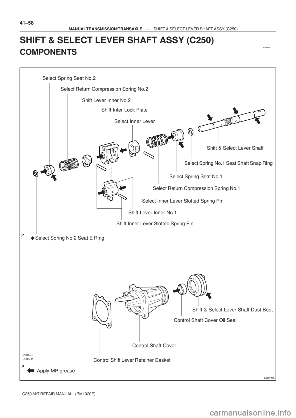
410DI±01
������������
D30695
Select Spring Seat No.2
�
Apply MP greaseSelect Spring No.2 Seat E Ring
Shift Lever Inner No.1
Shift Inner Lever Slotted Spring Pin Select Return Compression Spring No.2
Shift Lever Inner No.2
Shift Inter Lock Plate
Select Inner Lever
Select Return Compression Spring No.1
Select Inner Lever Slotted Spring Pin
Select Spring Seat No.1
Select Spring No.1 Seat Shaft Snap Ring
Shift & Select Lever Shaft
Control Shift Lever Retainer Gasket
Control Shaft Cover
Control Shaft Cover Oil SealShift & Select Lever Shaft Dust Boot
41±58
± MANUAL TRANSMISSION/TRANSAXLESHIFT & SELECT LEVER SHAFT ASSY (C250)
C250 M/T REPAIR MANUAL (RM1020E)
SHIFT & SELECT LEVER SHAFT ASSY (C250)
COMPONENTS

C250 M/T REPAIR MANUAL (RM1020E)
OVERHAUL
1. REMOVE SHIFT & SELECT LEVER BUSH
(a)")

C250 M/T REPAIR MANUAL (RM1020E)
20. INSTALL SELECTING BELLCRANK NO.2 BUSH
(a) C")