Page 3557 of 5135
C67657
C67656
C80586
C80386
Align alignment mark
C80387
± MANUAL TRANSMISSION/TRANSAXLEMANUAL TRANSAXLE ASSY (C250)
41±25
C250 M/T REPAIR MANUAL (RM1020E)
73. INSTALL MANUAL TRANSAXLE CASE RECEIVER
(a) Install the manual transaxle case receiver with bolt to the
front transaxle case.
Torque: 11 N�m (115 kgf�cm, 8.3 ft�lbf)
74. INSTALL DIFFERENTIAL CASE ASSY
(a) Coat the differential case tapered roller bearing with gear
oil, install them to the front transaxle case.
75. INSTALL INPUT SHAFT ASSY
(a) Coat sliding and rotating surface of the input and output
shafts with gear oil, install them to the transaxle case.
76. INSTALL REVERSE IDLER GEAR SUB±ASSY
(a) Coat the reverse idler gear, shim and reverse idler gear
shaft with gear oil, install them.
HINT:
Align the mark on the reverse idler gear shaft with the bolt hole
shown in the illustration.
77. INSTALL GEAR SHIFT FORK SHAFT NO.1
(a) Coat the gear shift fork No.1 and gear shift fork No.2 with
gear oil, install them.
Page 3558 of 5135
C80388
C80389
C80450
C80391
C80392
41±26
± MANUAL TRANSMISSION/TRANSAXLEMANUAL TRANSAXLE ASSY (C250)
C250 M/T REPAIR MANUAL (RM1020E)
(b) Coat the gear shift fork shaft No.1 with gear oil, install it.
(c) Apply sealant to the shift fork lock bolt.
Sealant:
Part No. 08833±00080, THREE BOND 1344, LOCTITE
242 or equivalent
(d) Install the gear shift fork lock bolt.
Torque: 16 N�m (160 kgf�cm, 12 ft�lbf)
(e) Using a brass bar and hammer, install the shaft snap ring
to the gear shift fork shaft No.1.
78. INSTALL GEAR SHIFT FORK SHAFT NO.3
(a) Coat the 2 shift fork balls with MP grease, install them to
the reverse shift fork.
(b) Install reverse shift fork to the shift fork shaft No.3.
(c) Using a brass bar and hammer, install 2 shift fork shaft
snap rings to the shift fork shaft No.3.
(d) Coat the shift fork shaft No.3 with gear oil, install it.
Page 3559 of 5135

C80362
C80361
C80360
C82142
FIPG
C80358
± MANUAL TRANSMISSION/TRANSAXLEMANUAL TRANSAXLE ASSY (C250)
41±27
C250 M/T REPAIR MANUAL (RM1020E)
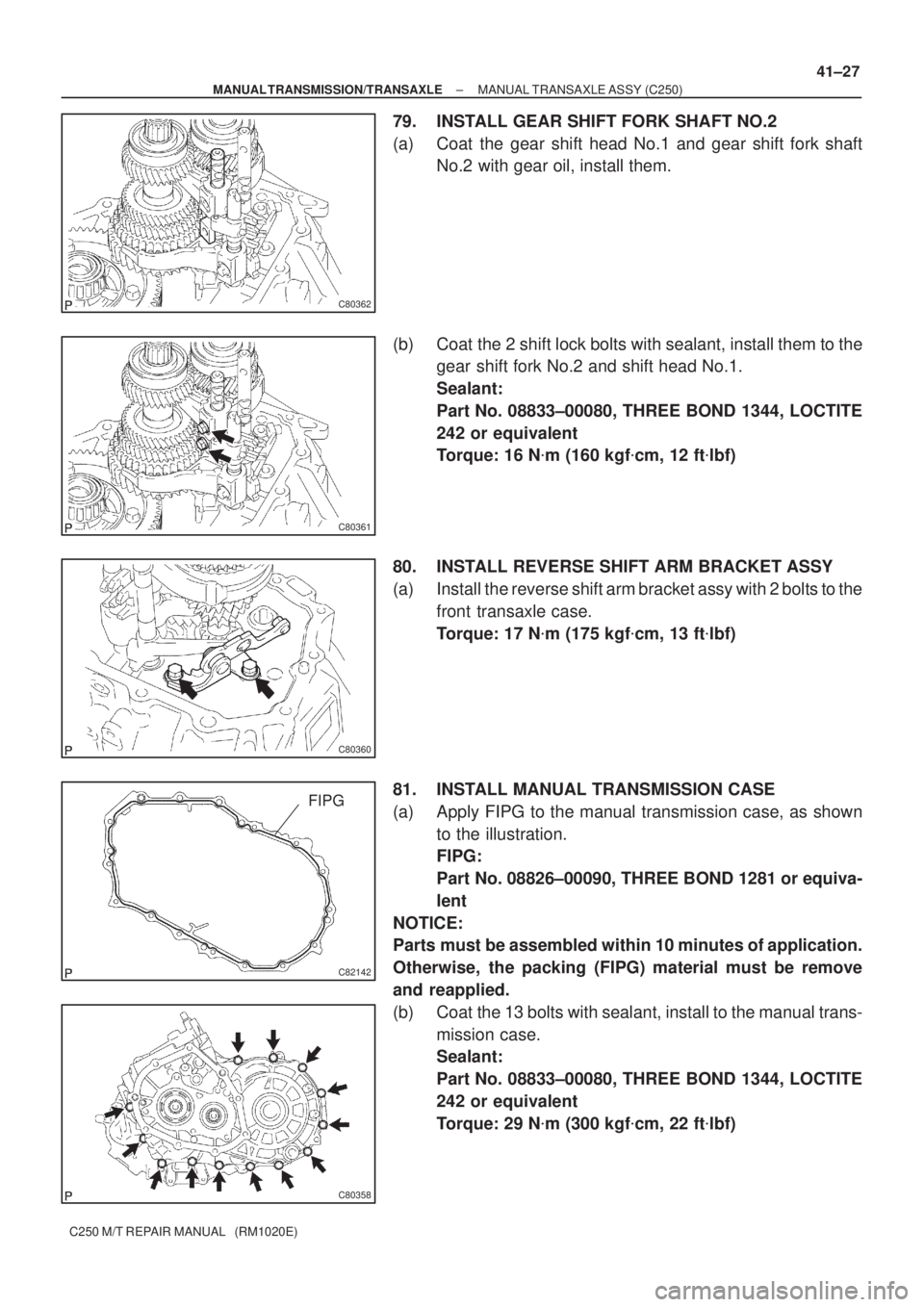
79. INSTALL GEAR SHIFT FORK SHAFT NO.2
(a) Coat the gear shift head No.1 and gear shift fork shaft
No.2 with gear oil, install them.
(b) Coat the 2 shift lock bolts with sealant, install them to the
gear shift fork No.2 and shift head No.1.
Sealant:
Part No. 08833±00080, THREE BOND 1344, LOCTITE
242 or equivalent
Torque: 16 N�m (160 kgf�cm, 12 ft�lbf)
80. INSTALL REVERSE SHIFT ARM BRACKET ASSY
(a) Install the reverse shift arm bracket assy with 2 bolts to the
front transaxle case.
Torque: 17 N�m (175 kgf�cm, 13 ft�lbf)
81. INSTALL MANUAL TRANSMISSION CASE
(a) Apply FIPG to the manual transmission case, as shown
to the illustration.
FIPG:
Part No. 08826±00090, THREE BOND 1281 or equiva-
lent
NOTICE:
Parts must be assembled within 10 minutes of application.
Otherwise, the packing (FIPG) material must be remove
and reapplied.
(b) Coat the 13 bolts with sealant, install to the manual trans-
mission case.
Sealant:
Part No. 08833±00080, THREE BOND 1344, LOCTITE
242 or equivalent
Torque: 29 N�m (300 kgf�cm, 22 ft�lbf)
Page 3560 of 5135

D30544
D30540
D30543
C68417
C67634
41±28
± MANUAL TRANSMISSION/TRANSAXLEMANUAL TRANSAXLE ASSY (C250)
C250 M/T REPAIR MANUAL (RM1020E)
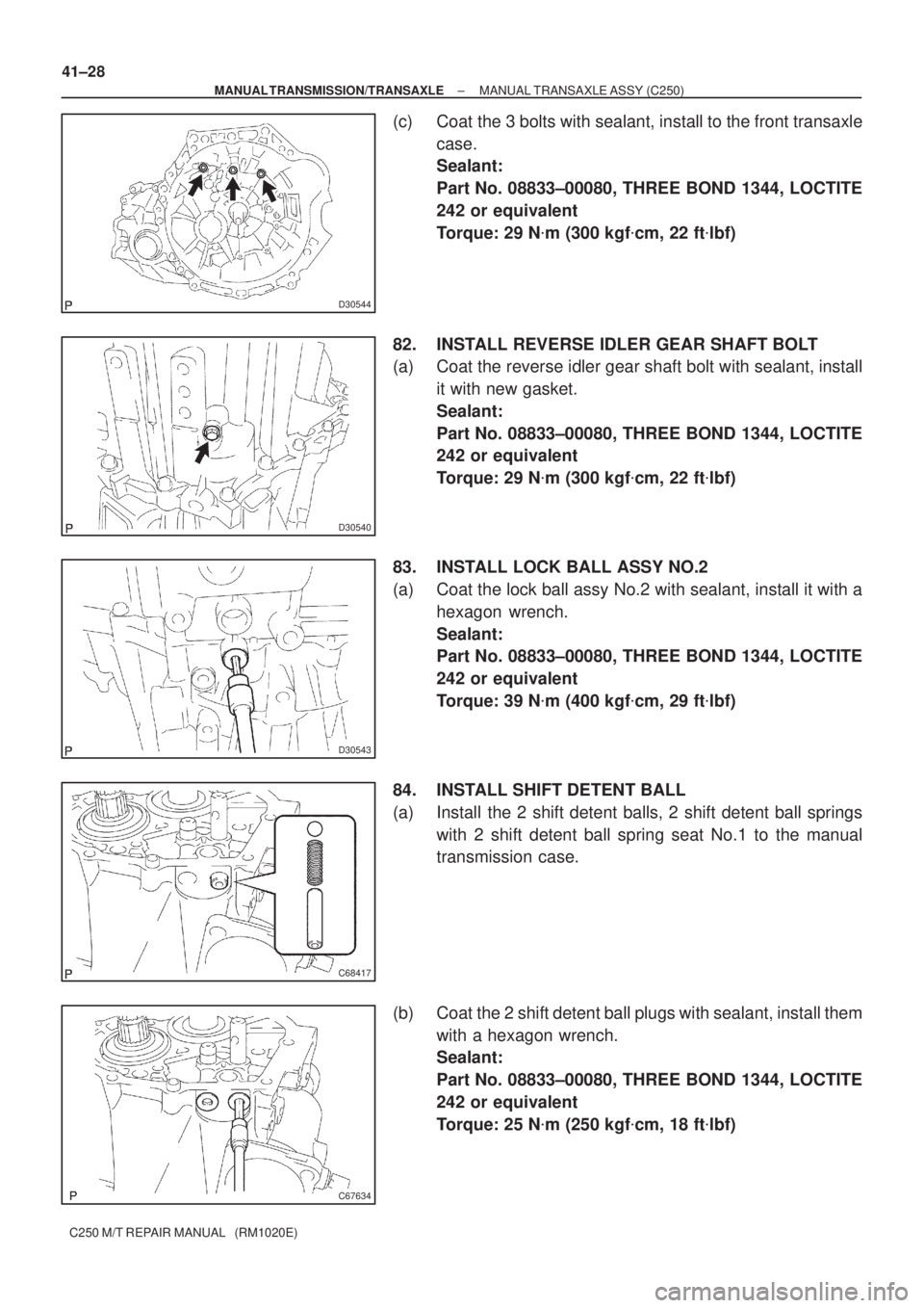
(c) Coat the 3 bolts with sealant, install to the front transaxle
case.
Sealant:
Part No. 08833±00080, THREE BOND 1344, LOCTITE
242 or equivalent
Torque: 29 N�m (300 kgf�cm, 22 ft�lbf)
82. INSTALL REVERSE IDLER GEAR SHAFT BOLT
(a) Coat the reverse idler gear shaft bolt with sealant, install
it with new gasket.
Sealant:
Part No. 08833±00080, THREE BOND 1344, LOCTITE
242 or equivalent
Torque: 29 N�m (300 kgf�cm, 22 ft�lbf)
83. INSTALL LOCK BALL ASSY NO.2
(a) Coat the lock ball assy No.2 with sealant, install it with a
hexagon wrench.
Sealant:
Part No. 08833±00080, THREE BOND 1344, LOCTITE
242 or equivalent
Torque: 39 N�m (400 kgf�cm, 29 ft�lbf)
84. INSTALL SHIFT DETENT BALL
(a) Install the 2 shift detent balls, 2 shift detent ball springs
with 2 shift detent ball spring seat No.1 to the manual
transmission case.
(b) Coat the 2 shift detent ball plugs with sealant, install them
with a hexagon wrench.
Sealant:
Part No. 08833±00080, THREE BOND 1344, LOCTITE
242 or equivalent
Torque: 25 N�m (250 kgf�cm, 18 ft�lbf)
Page 3561 of 5135
D30566
D30541
C80352
C80351
C80394
± MANUAL TRANSMISSION/TRANSAXLEMANUAL TRANSAXLE ASSY (C250)
41±29
C250 M/T REPAIR MANUAL (RM1020E)
(c) Install the shift detent ball, shift detent ball compression
spring and shift detent ball spring seat No.1 to the front
transaxle case.
(d) Coat the shift detent ball plug with sealant, install it with
using a hexagon wrench.
Sealant:
Part No. 08833±00080, THREE BOND 1344, LOCTITE
242 or equivalent
Torque: 25 N�m (250 kgf�cm, 18 ft�lbf)
85. INSTALL INPUT SHAFT REAR BEARING HOLE SNAP
RING
(a) Using a snap ring expander, install the input shaft rear
bearing hole snap ring to the input shaft.
86. INSTALL OUTPUT SHAFT REAR BEARING HOLE
SNAP RING
(a) Using a snap ring expander, install the output shaft rear
bearing hole snap ring to the output shaft.
87. INSTALL SHIFT FORK SHAFT SHAFT SNAP RING
(a) Using a brass bar and hammer, install the shift fork shaft
snap ring to the shift fork shaft No.2.
Page 3562 of 5135
D30539
D30568
SST
D30537
C80396
C80397
Key Position 41±30
± MANUAL TRANSMISSION/TRANSAXLEMANUAL TRANSAXLE ASSY (C250)
C250 M/T REPAIR MANUAL (RM1020E)
88. INSTALL BEARING RETAINER REAR (MTM)
(a) Coat the 5 bolts with sealant, install them and bearing re-
tainer rear to the manual transmission case.
Torque: 27 N�m (280 kgf�cm, 20 ft�lbf)
89. INSTALL 5TH DRIVEN GEAR
(a) Using SST, install the 5th driven gear to the output shaft.
SST 09950±30012 (09951±03010, 09953±03010,
09954±03010, 09955±03011, 09956±03020)
90. INSTALL 5TH GEAR NEEDLE ROLLER BEARING
(a) Coat the 5th gear needle roller bearing and spacer with
gear oil, install them to the input shaft.
91. INSTALL 5TH GEAR
(a) Coat the 5th gear with gear oil, install it to the input shaft.
92. INSTALL SYNCHRONIZER RING NO.3
(a) Coat the synchronizer ring No.3 with gear oil, install it to
the 5th gear.
Page 3563 of 5135

D30550
Engine
Side
D30551
Key Position
C80400
C80344
± MANUAL TRANSMISSION/TRANSAXLEMANUAL TRANSAXLE ASSY (C250)
41±31
C250 M/T REPAIR MANUAL (RM1020E)
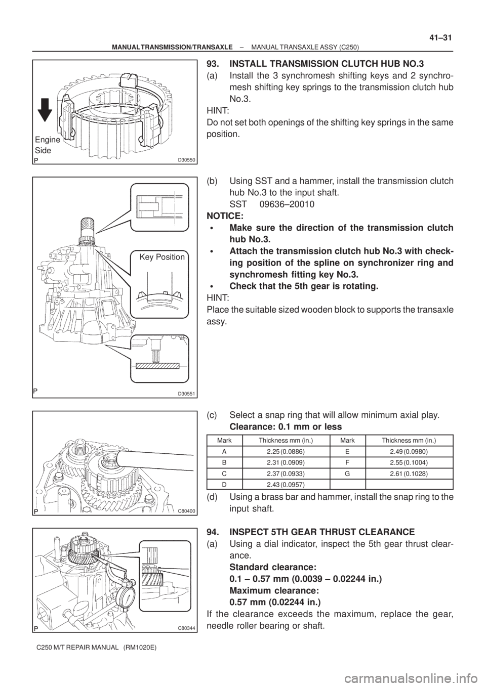
93. INSTALL TRANSMISSION CLUTCH HUB NO.3
(a) Install the 3 synchromesh shifting keys and 2 synchro-
mesh shifting key springs to the transmission clutch hub
No.3.
HINT:
Do not set both openings of the shifting key springs in the same
position.
(b) Using SST and a hammer, install the transmission clutch
hub No.3 to the input shaft.
SST 09636±20010
NOTICE:
�Make sure the direction of the transmission clutch
hub No.3.
�Attach the transmission clutch hub No.3 with check-
ing position of the spline on synchronizer ring and
synchromesh fitting key No.3.
�Check that the 5th gear is rotating.
HINT:
Place the suitable sized wooden block to supports the transaxle
assy.
(c) Select a snap ring that will allow minimum axial play.
Clearance: 0.1 mm or less
MarkThickness mm (in.)MarkThickness mm (in.)
A2.25 (0.0886)E2.49 (0.0980)
B2.31 (0.0909)F2.55 (0.1004)
C2.37 (0.0933)G2.61 (0.1028)
D2.43 (0.0957)
(d) Using a brass bar and hammer, install the snap ring to the
input shaft.
94. INSPECT 5TH GEAR THRUST CLEARANCE
(a) Using a dial indicator, inspect the 5th gear thrust clear-
ance.
Standard clearance:
0.1 ± 0.57 mm (0.0039 ± 0.02244 in.)
Maximum clearance:
0.57 mm (0.02244 in.)
If the clearance exceeds the maximum, replace the gear,
needle roller bearing or shaft.
Page 3564 of 5135

C80345
C80401
C80402
C80403
C80404
41±32
± MANUAL TRANSMISSION/TRANSAXLEMANUAL TRANSAXLE ASSY (C250)
C250 M/T REPAIR MANUAL (RM1020E)
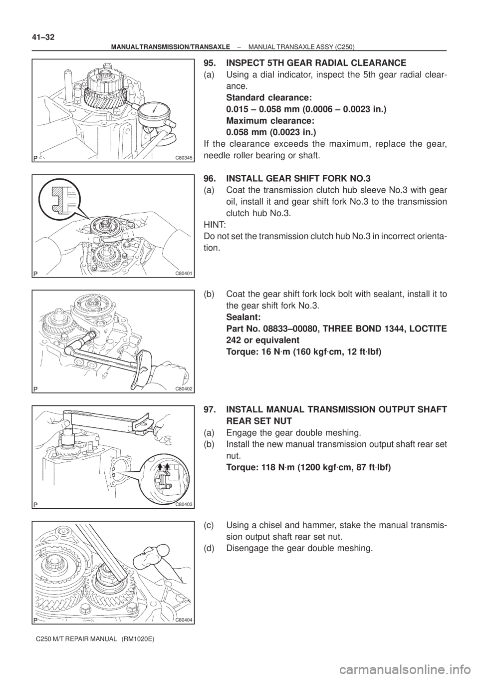
95. INSPECT 5TH GEAR RADIAL CLEARANCE
(a) Using a dial indicator, inspect the 5th gear radial clear-
ance.
Standard clearance:
0.015 ± 0.058 mm (0.0006 ± 0.0023 in.)
Maximum clearance:
0.058 mm (0.0023 in.)
If the clearance exceeds the maximum, replace the gear,
needle roller bearing or shaft.
96. INSTALL GEAR SHIFT FORK NO.3
(a) Coat the transmission clutch hub sleeve No.3 with gear
oil, install it and gear shift fork No.3 to the transmission
clutch hub No.3.
HINT:
Do not set the transmission clutch hub No.3 in incorrect orienta-
tion.
(b) Coat the gear shift fork lock bolt with sealant, install it to
the gear shift fork No.3.
Sealant:
Part No. 08833±00080, THREE BOND 1344, LOCTITE
242 or equivalent
Torque: 16 N�m (160 kgf�cm, 12 ft�lbf)
97. INSTALL MANUAL TRANSMISSION OUTPUT SHAFT
REAR SET NUT
(a) Engage the gear double meshing.
(b) Install the new manual transmission output shaft rear set
nut.
Torque: 118 N�m (1200 kgf�cm, 87 ft�lbf)
(c) Using a chisel and hammer, stake the manual transmis-
sion output shaft rear set nut.
(d) Disengage the gear double meshing.