Page 3549 of 5135
C82141
SST
C67719
C81785
SST
C82145
SST
C81789
SST
± MANUAL TRANSMISSION/TRANSAXLEMANUAL TRANSAXLE ASSY (C250)
41±17
C250 M/T REPAIR MANUAL (RM1020E)
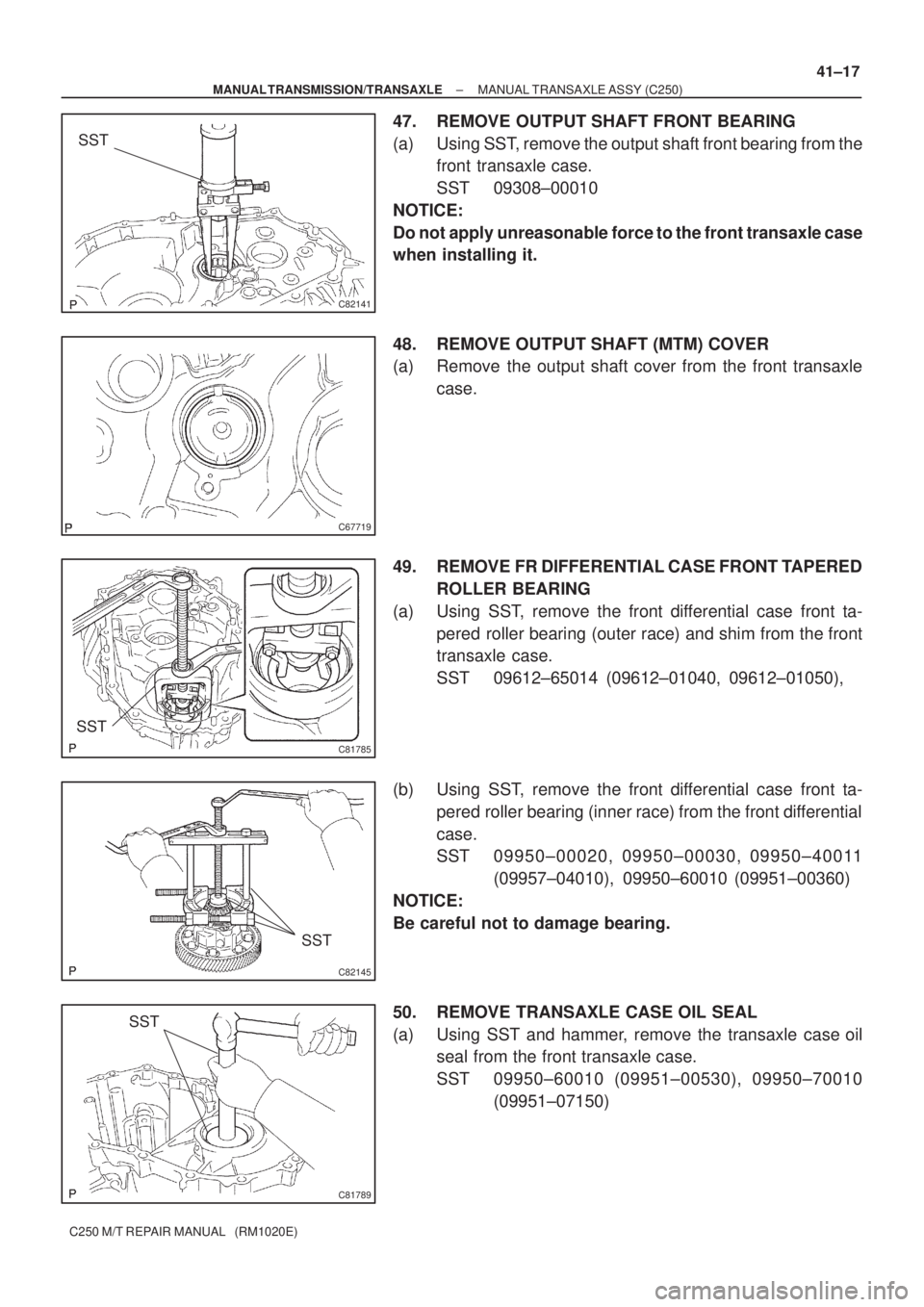
47. REMOVE OUTPUT SHAFT FRONT BEARING
(a) Using SST, remove the output shaft front bearing from the
front transaxle case.
SST 09308±00010
NOTICE:
Do not apply unreasonable force to the front transaxle case
when installing it.
48. REMOVE OUTPUT SHAFT (MTM) COVER
(a) Remove the output shaft cover from the front transaxle
case.
49. REMOVE FR DIFFERENTIAL CASE FRONT TAPERED
ROLLER BEARING
(a) Using SST, remove the front differential case front ta-
pered roller bearing (outer race) and shim from the front
transaxle case.
SST 09612±65014 (09612±01040, 09612±01050),
(b) Using SST, remove the front differential case front ta-
pered roller bearing (inner race) from the front differential
case.
SST 09950±00020, 09950±00030, 09950±40011
(09957±04010), 09950±60010 (09951±00360)
NOTICE:
Be careful not to damage bearing.
50. REMOVE TRANSAXLE CASE OIL SEAL
(a) Using SST and hammer, remove the transaxle case oil
seal from the front transaxle case.
SST 09950±60010 (09951±00530), 09950±70010
(09951±07150)
Page 3550 of 5135
C81788
SST
C82144
SST
C81787
SST
D30571
SST
C67848
41±18
± MANUAL TRANSMISSION/TRANSAXLEMANUAL TRANSAXLE ASSY (C250)
C250 M/T REPAIR MANUAL (RM1020E)
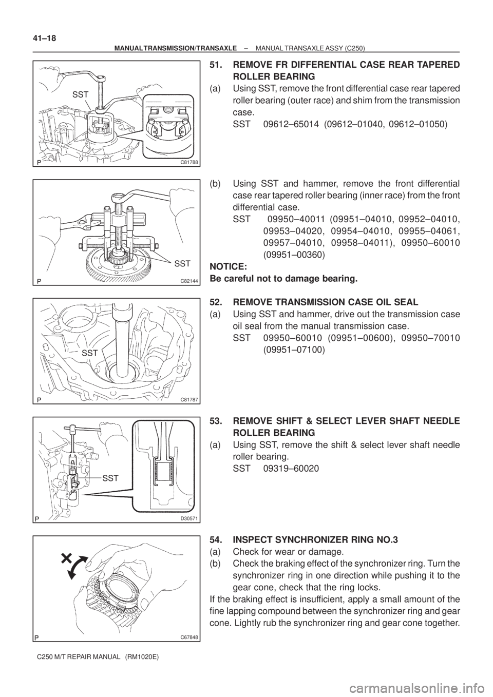
51. REMOVE FR DIFFERENTIAL CASE REAR TAPERED
ROLLER BEARING
(a) Using SST, remove the front differential case rear tapered
roller bearing (outer race) and shim from the transmission
case.
SST 09612±65014 (09612±01040, 09612±01050)
(b) Using SST and hammer, remove the front differential
case rear tapered roller bearing (inner race) from the front
differential case.
SST 09950±40011 (09951±04010, 09952±04010,
09953±04020, 09954±04010, 09955±04061,
09957±04010, 09958±04011), 09950±60010
(09951±00360)
NOTICE:
Be careful not to damage bearing.
52. REMOVE TRANSMISSION CASE OIL SEAL
(a) Using SST and hammer, drive out the transmission case
oil seal from the manual transmission case.
SST 09950±60010 (09951±00600), 09950±70010
(09951±07100)
53. REMOVE SHIFT & SELECT LEVER SHAFT NEEDLE
ROLLER BEARING
(a) Using SST, remove the shift & select lever shaft needle
roller bearing.
SST 09319±60020
54. INSPECT SYNCHRONIZER RING NO.3
(a) Check for wear or damage.
(b) Check the braking effect of the synchronizer ring. Turn the
synchronizer ring in one direction while pushing it to the
gear cone, check that the ring locks.
If the braking effect is insufficient, apply a small amount of the
fine lapping compound between the synchronizer ring and gear
cone. Lightly rub the synchronizer ring and gear cone together.
Page 3551 of 5135
C67850
C67978
C80375
± MANUAL TRANSMISSION/TRANSAXLEMANUAL TRANSAXLE ASSY (C250)
41±19
C250 M/T REPAIR MANUAL (RM1020E)
NOTICE:
Ensure the fine lapping compound is completely washed
off after rubbing.
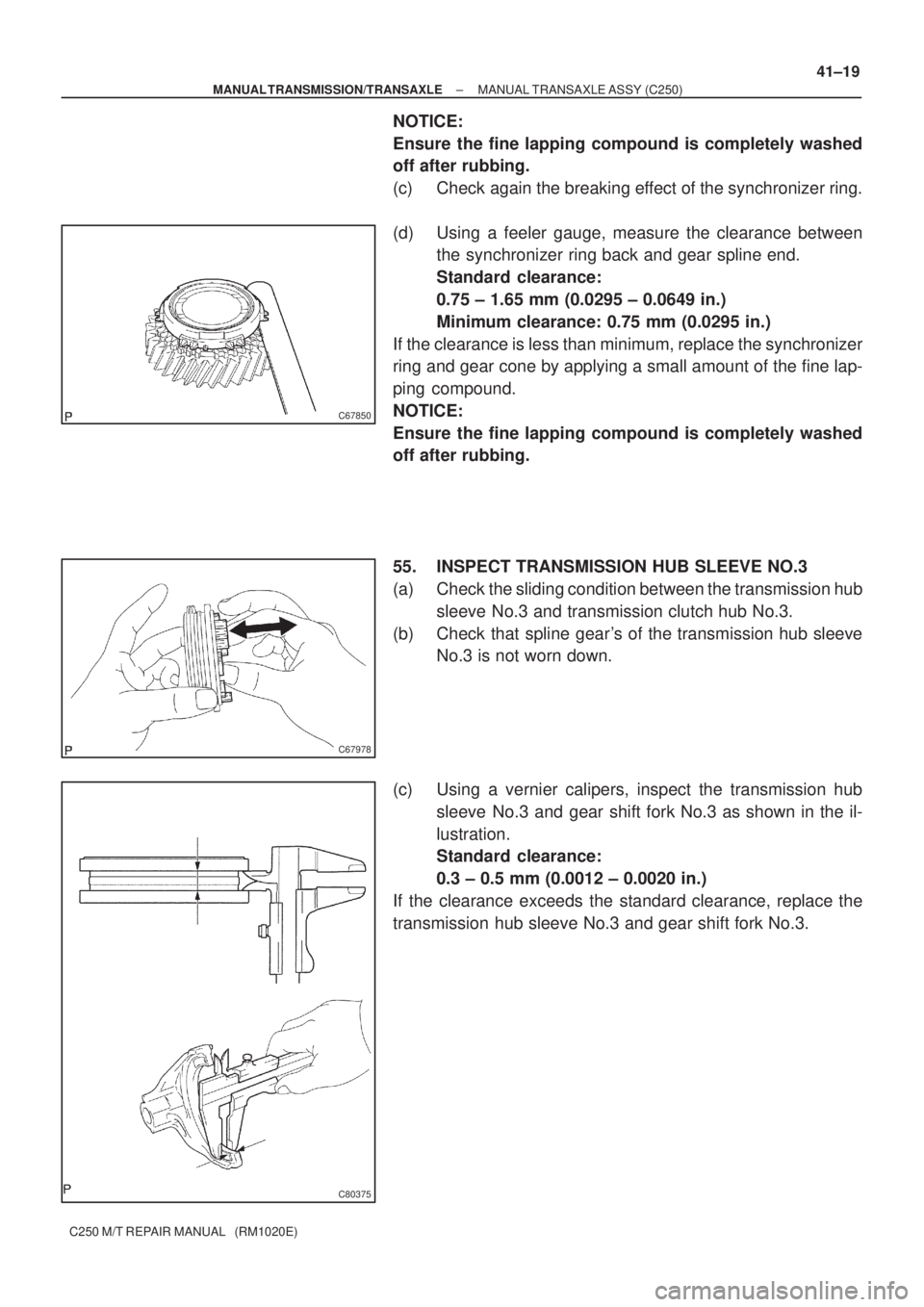
(c) Check again the breaking effect of the synchronizer ring.
(d) Using a feeler gauge, measure the clearance between
the synchronizer ring back and gear spline end.
Standard clearance:
0.75 ± 1.65 mm (0.0295 ± 0.0649 in.)
Minimum clearance: 0.75 mm (0.0295 in.)
If the clearance is less than minimum, replace the synchronizer
ring and gear cone by applying a small amount of the fine lap-
ping compound.
NOTICE:
Ensure the fine lapping compound is completely washed
off after rubbing.
55. INSPECT TRANSMISSION HUB SLEEVE NO.3
(a) Check the sliding condition between the transmission hub
sleeve No.3 and transmission clutch hub No.3.
(b) Check that spline gear's of the transmission hub sleeve
No.3 is not worn down.
(c) Using a vernier calipers, inspect the transmission hub
sleeve No.3 and gear shift fork No.3 as shown in the il-
lustration.
Standard clearance:
0.3 ± 0.5 mm (0.0012 ± 0.0020 in.)
If the clearance exceeds the standard clearance, replace the
transmission hub sleeve No.3 and gear shift fork No.3.
Page 3552 of 5135
C67975
C67846
C67719
C80376
SST 41±20
± MANUAL TRANSMISSION/TRANSAXLEMANUAL TRANSAXLE ASSY (C250)
C250 M/T REPAIR MANUAL (RM1020E)
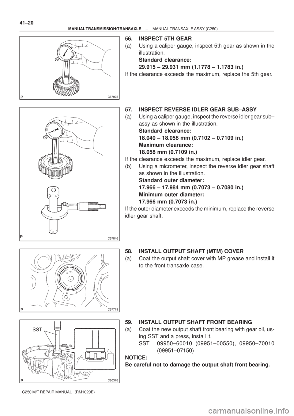
56. INSPECT 5TH GEAR
(a) Using a caliper gauge, inspect 5th gear as shown in the
illustration.
Standard clearance:
29.915 ± 29.931 mm (1.1778 ± 1.1783 in.)
If the clearance exceeds the maximum, replace the 5th gear.
57. INSPECT REVERSE IDLER GEAR SUB±ASSY
(a) Using a caliper gauge, inspect the reverse idler gear sub±
assy as shown in the illustration.
Standard clearance:
18.040 ± 18.058 mm (0.7102 ± 0.7109 in.)
Maximum clearance:
18.058 mm (0.7109 in.)
If the clearance exceeds the maximum, replace idler gear.
(b) Using a micrometer, inspect the reverse idler gear shaft
as shown in the illustration.
Standard outer diameter:
17.966 ± 17.984 mm (0.7073 ± 0.7080 in.)
Minimum outer diameter:
17.966 mm (0.7073 in.)
If the outer diameter exceeds the minimum, replace the reverse
idler gear shaft.
58. INSTALL OUTPUT SHAFT (MTM) COVER
(a) Coat the output shaft cover with MP grease and install it
to the front transaxle case.
59. INSTALL OUTPUT SHAFT FRONT BEARING
(a) Coat the new output shaft front bearing with gear oil, us-
ing SST and a press, install it.
SST 09950±60010 (09951±00550), 09950±70010
(09951±07150)
NOTICE:
Be careful not to damage the output shaft front bearing.
Page 3553 of 5135
C81790
SST
C81791
SST
D30572
SST
C82146
SST
C80379
SST
± MANUAL TRANSMISSION/TRANSAXLEMANUAL TRANSAXLE ASSY (C250)
41±21
C250 M/T REPAIR MANUAL (RM1020E)
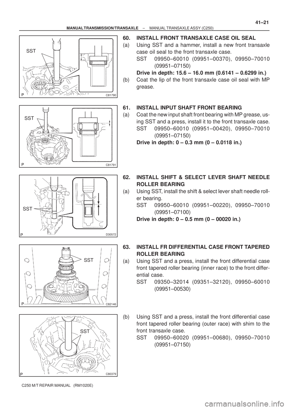
60. INSTALL FRONT TRANSAXLE CASE OIL SEAL
(a) Using SST and a hammer, install a new front transaxle
case oil seal to the front transaxle case.
SST 09950±60010 (09951±00370), 09950±70010
(09951±07150)
Drive in depth: 15.6 ± 16.0 mm (0.6141 ± 0.6299 in.)
(b) Coat the lip of the front transaxle case oil seal with MP
grease.
61. INSTALL INPUT SHAFT FRONT BEARING
(a) Coat the new input shaft front bearing with MP grease, us-
ing SST and a press, install it to the front transaxle case.
SST 09950±60010 (09951±00420), 09950±70010
(09951±07150)
Drive in depth: 0 ± 0.3 mm (0 ± 0.0118 in.)
62. INSTALL SHIFT & SELECT LEVER SHAFT NEEDLE
ROLLER BEARING
(a) Using SST, install the shift & select lever shaft needle roll-
er bearing.
SST 09950±60010 (09951±00220), 09950±70010
(09951±07100)
Drive in depth: 0 ± 0.5 mm (0 ± 00020 in.)
63. INSTALL FR DIFFERENTIAL CASE FRONT TAPERED
ROLLER BEARING
(a) Using SST and a press, install the front differential case
front tapered roller bearing (inner race) to the front differ-
ential case.
SST 09350±32014 (09351±32120), 09950±60010
(09951±00530)
(b) Using SST and a press, install the front differential case
front tapered roller bearing (outer race) with shim to the
front transaxle case.
SST 09950±60020 (09951±00680), 09950±70010
(09951±07150)
Page 3554 of 5135
C82147
SST
D30548
SST
C67656
C81793
SST
C81793
SST 41±22
± MANUAL TRANSMISSION/TRANSAXLEMANUAL TRANSAXLE ASSY (C250)
C250 M/T REPAIR MANUAL (RM1020E)
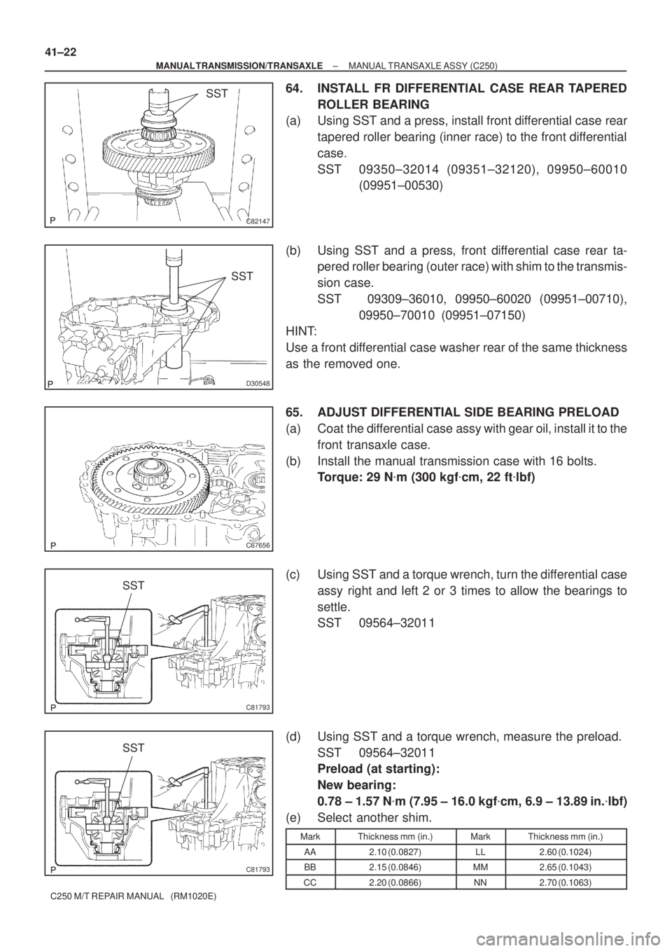
64. INSTALL FR DIFFERENTIAL CASE REAR TAPERED
ROLLER BEARING
(a) Using SST and a press, install front differential case rear
tapered roller bearing (inner race) to the front differential
case.
SST 09350±32014 (09351±32120), 09950±60010
(09951±00530)
(b) Using SST and a press, front differential case rear ta-
pered roller bearing (outer race) with shim to the transmis-
sion case.
SST 09309±36010, 09950±60020 (09951±00710),
09950±70010 (09951±07150)
HINT:
Use a front differential case washer rear of the same thickness
as the removed one.
65. ADJUST DIFFERENTIAL SIDE BEARING PRELOAD
(a) Coat the differential case assy with gear oil, install it to the
front transaxle case.
(b) Install the manual transmission case with 16 bolts.
Torque: 29 N�m (300 kgf�cm, 22 ft�lbf)
(c) Using SST and a torque wrench, turn the differential case
assy right and left 2 or 3 times to allow the bearings to
settle.
SST 09564±32011
(d) Using SST and a torque wrench, measure the preload.
SST 09564±32011
Preload (at starting):
New bearing:
0.78 ± 1.57 N�m (7.95 ± 16.0 kgf�cm, 6.9 ± 13.89 in.�lbf)
(e) Select another shim.
MarkThickness mm (in.)MarkThickness mm (in.)
AA2.10 (0.0827)LL2.60 (0.1024)
BB2.15 (0.0846)MM2.65 (0.1043)
CC2.20 (0.0866)NN2.70 (0.1063)
Page 3555 of 5135
C80381
SST
C80382
SST
C67659
C67658
± MANUAL TRANSMISSION/TRANSAXLEMANUAL TRANSAXLE ASSY (C250)
41±23
C250 M/T REPAIR MANUAL (RM1020E)Mark Thickness mm (in.)Mark Thickness mm (in.)
DD2.25 (0.0886)PP2.75 (0.1083)
EE2.30 (0.0906)QQ2.80 (0.1102)
FF2.35 (0.0925)RR2.85 (0.1122)
GG2.40 (0.0945)SS2.90 (0.1142)
HH2.45 (0.0965)TT2.95 (0.1161)
JJ2.50 (0.0984)UU3.00 (0.1181)
KK2.55 (0.1004)±±
(f) Remove the 16 bolts and manual transmission case.
(g) Remove the differential case assy.
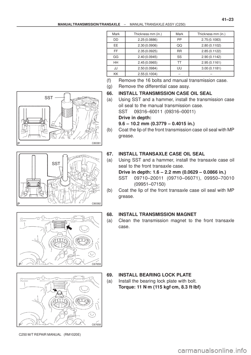
66. INSTALL TRANSMISSION CASE OIL SEAL
(a) Using SST and a hammer, install the transmission case
oil seal to the manual transmission case.
SST 09316±60011 (09316±00011)
Drive in depth:
9.6 ± 10.2 mm (0.3779 ± 0.4015 in.)
(b) Coat the lip of the front transmission case oil seal with MP
grease.
67. INSTALL TRANSAXLE CASE OIL SEAL
(a) Using SST and a hammer, install the transaxle case oil
seal to the front transaxle case.
Drive in depth: 1.6 ± 2.2 mm (0.0629 ± 0.0866 in.)
SST 09710±20011 (09710±06071), 09950±70010
(09951±07150)
(b) Coat the lip of the front transaxle case oil seal with MP
grease.
68. INSTALL TRANSMISSION MAGNET
(a) Clean the transmission magnet to the front transaxle
case.
69. INSTALL BEARING LOCK PLATE
(a) Install the bearing lock plate with bolt.
Torque: 11 N�m (115 kgf�cm, 8.3 ft�lbf)
Page 3556 of 5135
C68380
C80432
C80383
C80384
D30549
41±24
± MANUAL TRANSMISSION/TRANSAXLEMANUAL TRANSAXLE ASSY (C250)
C250 M/T REPAIR MANUAL (RM1020E)
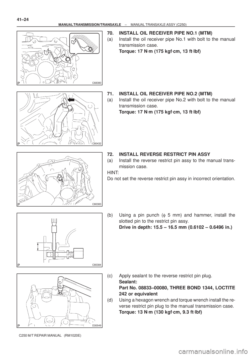
70. INSTALL OIL RECEIVER PIPE NO.1 (MTM)
(a) Install the oil receiver pipe No.1 with bolt to the manual
transmission case.
Torque: 17 N�m (175 kgf�cm, 13 ft�lbf)
71. INSTALL OIL RECEIVER PIPE NO.2 (MTM)
(a) Install the oil receiver pipe No.2 with bolt to the manual
transmission case.
Torque: 17 N�m (175 kgf�cm, 13 ft�lbf)
72. INSTALL REVERSE RESTRICT PIN ASSY
(a) Install the reverse restrict pin assy to the manual trans-
mission case.
HINT:
Do not set the reverse restrict pin assy in incorrect orientation.
(b) Using a pin punch (� 5 mm) and hammer, install the
slotted pin to the restrict pin assy.
Drive in depth: 15.5 ± 16.5 mm (0.6102 ± 0.6496 in.)
(c) Apply sealant to the reverse restrict pin plug.
Sealant:
Part No. 08833±00080, THREE BOND 1344, LOCTITE
242 or equivalent
(d) Using a hexagon wrench and torque wrench install the re-
verse restrict pin plug to the manual transmission case.
Torque: 13 N�m (130 kgf�cm, 9.3 ft�lbf)