Page 1728 of 5135

B67699
S+B
IOUT 24
26 L±W
L±B 9 T12
Theft Warning Radar Sensor
6 S+B
IOUT
SOFF7
W±BSSW1
13 LG±B
ID18T6
Theft Warning ECU Assy
T14
Rear Theft Warning
Radar Sensor (IN)
T13
Rear Theft Warning
Radar Sensor (OUT)
IJ DA DK9 6 LG±B L±B L±W
ID1 ID1
W±B 19
SOU+
SOU±GND SIN+
SIN± 2
1
2
18
4
1 53 W
P
L
2 MIN+
MIN±
MOU+
MOU±Instrument Panel J/B Assy Shielded 05±1650
± DIAGNOSTICSTHEFT DETERRENT SYSTEM
AVENSIS REPAIR MANUAL (RM1018E)
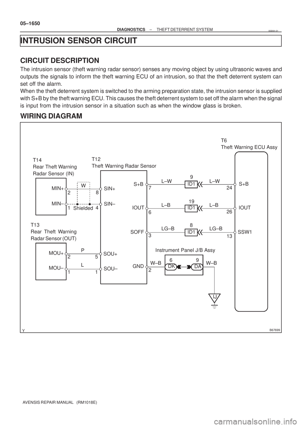
INTRUSION SENSOR CIRCUIT
CIRCUIT DESCRIPTION
The intrusion sensor (theft warning radar sensor) senses any moving object by using ultrasonic waves and
outputs the signals to inform the theft warning ECU of an intrusion, so that the theft deterrent system can
set off the alarm.
When the theft deterrent system is switched to the arming preparation state, the intrusion sensor is supplied
with S+B by the theft warning ECU. This causes the theft deterrent system to set off the alarm when the signal
is input from the intrusion sensor in a situation such as when the window glass is broken.
WIRING DIAGRAM
05BAH±01
Page 1732 of 5135

B67700
CTLS
27 L±R
IM111 T15
Theft Warning Siren Assy
W±R
CI CC7
2
2
4AECU±B2 Fuse Block 10
1 W±R
B*
2
Battery Center J/B Assy
6T6
Theft Warning ECU Assy
BW
+B
3 W±R
B±G*
1
L±R
IM112
GND CONT
6
IP15
B±W B±W
Engine Room R/B
DCC
1 21
1 1A
B*
2B±G*1
4B
Main3
3 11W±B
*
1: Gasoline
*2: 1CD±FTV1
Engine Room
R/B No. 3 Engine Room
J/B No. 4
± DIAGNOSTICSTHEFT DETERRENT SYSTEM
05±1647
AVENSIS REPAIR MANUAL (RM1018E)
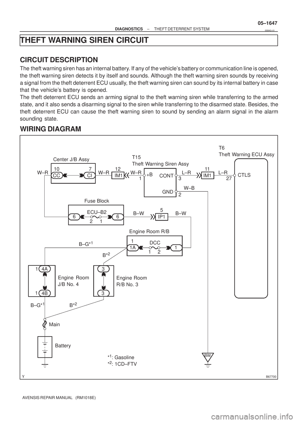
THEFT WARNING SIREN CIRCUIT
CIRCUIT DESCRIPTION
The theft warning siren has an internal battery. If any of the vehicle's battery or communication line is opened,
the theft warning siren detects it by itself and sounds. Although the theft warning siren sounds by receiving
a signal from the theft deterrent ECU usually, the theft warning siren can sound by its internal battery in case
that the vehicle's battery is opened.
The theft deterrent ECU sends an arming signal to the theft warning siren while transferring to the armed
state, and it also sends a disarming signal to the siren while transferring to the disarmed state. Besides, the
theft deterrent ECU can cause the theft warning siren to sound by sending an alarm signal in the alarm
sounding state.
WIRING DIAGRAM
05BAG±01
Page 1735 of 5135
B67701
Battery MainEngine Room R/B12
1T7
Theft Warning ECU Assy
G
HORN
B±G*
1
HORN Relay
G±W20
1H11
Horn
(Low) W
H12
Horn
(High)IE1J26
J/C
B
HORN5 Engine Room R/B No. 2
B G G
32
2 2 2
5
W
1
1A 1
1 3
3
B±G*
1
B*2
B*2
4A
4B1
1
*
1: Gasoline
*2: 1CD±FTV Engine Room
R/B No. 3 Engine
Room J/B
No. 4
G±W 05±1644
± DIAGNOSTICSTHEFT DETERRENT SYSTEM
AVENSIS REPAIR MANUAL (RM1018E)
HORN CIRCUIT
CIRCUIT DESCRIPTION
When the theft deterrent system is transferred from the armed state to the alarm sounding state, the theft
warning ECU switches on the HORN relay causing the horns to sound. The horn sounds at an interval of
0.4 seconds.
WIRING DIAGRAM
05BAF±01
Page 1738 of 5135
B68375
E6
Engine Hood Courtesy Switch
W±B
1 3IO15
DSWH
34 L±RT6
Theft Warning ECU Assy
ECL±R
B67861
Free
(ON)
Pushed
(OFF)
05±1642
± DIAGNOSTICSTHEFT DETERRENT SYSTEM
AVENSIS REPAIR MANUAL (RM1018E)
ENGINE HOOD COURTESY SWITCH CIRCUIT
CIRCUIT DESCRIPTION
The engine hood courtesy switch is installed together with the hood lock assy. This switch comes on when
the engine hood is opened and goes off when the engine hood is closed.
WIRING DIAGRAM
INSPECTION PROCEDURE
1 INSPECT ENGINE HOOD COURTESY SWITCH
(a) Remove the engine hood courtesy switch from the hood
lock assy.
(b) Check the resistance.
Tester ConnectionSwitch PositionSpecified Condition
13Pushed (OFF (Lock))10 k� or higher1 ± 3Free (ON (Unlock))Below 1 �
NG REPAIR OR REPLACE ENGINE HOOD
COURTESY SWITCH
OK
05BAE±01
Page 1742 of 5135
I35707
1AZ±FSE
D5
DLC3
TC
CG13
4W±L
W±B
W±B W±LW±L
W±BW±L
TC 20
E12 17 3
DB DC
CB CA36 DBB
B
A J21 J20J8
J8
J16
J/C
IOIP Center J/B Driver Side J/BECM
*2: RHD *1: LHD (*1)(*1)
(*1)(*2)
(*2)
(*2)
(*1) (*2)
(*2) J/B
A
W±B
± DIAGNOSTICSCRUISE CONTROL SYSTEM
05±1729
AVENSIS REPAIR MANUAL (RM1018E)
DIAGNOSIS CIRCUIT
CIRCUIT DESCRIPTION
Making short circuit between terminal TC and CG of DLC3 will output DTC from the DLC3.
WIRING DIAGRAM
05C4V±01
Page 1746 of 5135
I35709
C9
Clutch Start
SW Assy
R±W R±W
R±W R±W
R±W
W±B W±B LG±B
LG±BLG±B
LG±BLG±B
LG±B (*1)
(*2)12 9
515
6
21
568
610 J14
J/C
J19
J/C
DECM
E11
DD
6
IP CPU
CRUISEC11
C11CD
CKCE
CA Center J/B Combination Meter AssyIE2
IR1IE2
IR1 (*1) (*1) (*1) (*1)
CC
(*2)
(*2)(*2)
(*2)
*1: LHD
*2: RHD 1AZ±FSE (M/T) 05±1722
± DIAGNOSTICSCRUISE CONTROL SYSTEM
AVENSIS REPAIR MANUAL (RM1018E)
CRUISE MAIN INDICATOR LIGHT CIRCUIT
CIRCUIT DESCRIPTION
When the cruise control main switch is turned off, the cruise control does not operate.
WIRING DIAGRAM
05C4U±01
Page 1753 of 5135
I35711
C14
Combination SW
CANCEL SET/COASTRES/ACC
CRUISE
CCS
CCSW24
E11
J/C
E J13
J13
J13
J12 ECC 3
BR
BR
BR2 1AZ±FSE
ECU
EE
E
E
D
Cruise Control Main Switch Assy 05±1718
± DIAGNOSTICSCRUISE CONTROL SYSTEM
AVENSIS REPAIR MANUAL (RM1018E)
CRUISE CONTROL SWITCH CIRCUIT
CIRCUIT DESCRIPTION
This circuit carries the SET/COAST, RES/ACC and CANCEL signals (each voltage) to the ECM.
WIRING DIAGRAM
05C4T±01
Page 1759 of 5135
I35714
ECM
19
E11
STP
12
E11 ST1± R±WR±W
G±W
G±W(*1)
(*2)
(*1)
(*2) G±W
R±W
R±W
G±W
G±W(*1)
(*2)
(*1)
(*2) S13
Stop Lamp
Switch Assy
Engine Room R/B G±W
G±W G±W
G±W
B±W B±W
B±W B±W(*1) (*1)
(*2) (*2)
(*1)
(*1)
(*2) (*2)11
2
14
4 6
1
20
3IE3
IR1
IE2
IR1 IE3
IR1
IE1
IR1
4 312
I13
Ignition SW
B±R B±R
IG2 AM24
611
IE4 IP1
(*2) (*1)
B±R
1 1
1AAM2
12
Driver Side J/B Engine Room J/B No.4Driver Side J/B
ALT IGN
1
21
1 4A
4DB±G
1STOP
22
DN DA 1
4B B±G
FL MAIN
Battery2 18
DA DHDA DC10 2Driver Side J/B
J26 J8
J27 J9 AC ECJ/C
B±G (*2)(*2)
(*1)(*1)
*1: LHD
*2: RHD 1AZ±FSE
B±W 05±1712
± DIAGNOSTICSCRUISE CONTROL SYSTEM
AVENSIS REPAIR MANUAL (RM1018E)
WIRING DIAGRAM