Page 1613 of 5135
B66819
DCTY
Integration Relay
KSW 13
DB D9
Front Door Courtesy Lamp Switch Assy
(Driver Side)
128
DA U1
Unlock Warning Switch AssyInstrument Panel J/B Assy
1 LHD models
R14
IC2J10
J/C
B
Y W±B J16
J/C
A
*
2: 1CD±FTVB
RR
A
IO*
1
IL*2
*1: Gasoline
W±B17
19
± DIAGNOSTICSPOWER DOOR LOCK CONTROL SYSTEM
05±1555
AVENSIS REPAIR MANUAL (RM1018E)
KEY LOCK±IN PREVENTION FUNCTION DOES NOT WORK
PROPERLY (MANUAL OPERATION AND OPERATION
INTERLOCKED WITH KEY ARE ACTIVE)
CIRCUIT DESCRIPTION
The unlock warning switch turns ON when the key is inserted into the ignition key cylinder. The courtesy
lamp switch turns ON when the driver side door is opened. These 2 switches are monitored by the integration
relay. In order to prevent the key from being locked in, the integration relay controls door locking operation
according to the conditions of these switches so that the doors are not locked with the key locked in.
WIRING DIAGRAM
05C8C±01
Page 1619 of 5135

B66818
ACT+ L1
UL1
Integration Relay
DA
DA11
10 29
13
5 8
D17
Power Window Regulator
Master Switch Assy (Door Control Switch)
7
L2 9
10
18
4 7
D13
Front Door w/ Motor Lock Assy LH
UL2
LSWD
ACT±
20
10
D15
Front Door w/ Motor Lock Assy RH
B7
Back Door Lock AssyInstrument Panel J/B Assy
LHD Models
4
5
3
DJ1
DJ4
DM7
DM6
1 4
D18
Rear Door w/ Motor Lock Assy LH
DB
DB 1 4D20
Rear Door w/ Motor
Lock Assy RH
1 4
BDCYI1412
12
4
3
LACT4
DM3
1
2
3 2
12
L3 Back Door Lock Assy
I14 Back Door Opener
Switch Assy
(Outside Handle Switch)
L4 Back Door Opener Switch Assy
LGCY
1
1BDSU
10 W±BBR±W
IA2
IC1
IA1
BA1
CA
CJ
CC
CC
CK IL1
BC1IM2
BE2
BG2R±Y*
3BF2
BD2
J34A
W±B*2J/C
J31 IA1
IJG±W
IA2
IC1
IC1
IA1BR±W
G±W 4
3
17
7
16
7
2
2
11
BA1 L±R
L
L±R
L±B
Center J/B LG
L±R
L±B
L±R
L±B
L±R
L±B L±R
L±B L±R
L±B
BC1IL1
IM2
R±Y*
3
R±Y*4R±Y*4
8
5 2
117
172
1
W±B*2
W±B*2
BE2
5 4
BG27
L*
4
L*3
J34
J34
BX
BS
J30 W±B*
1C
B
B J30W±B*1
W±B*1
A
AA
J33 BE26*
4*3R±Y*
228
A
A
I14
I14
L±B*
1 A
A
J32 J/C
R±Y*1
R±Y*1
L*3BF2BD2
*4*3
7 6
L*2
L*1
BF2BD26
*4*3
CBL±R
L±B
L±R
L±B
8 7
7
112 4
L±R
L±B
L*
4
L±B*3L±B*2L*3
L±R*2L±Y*1
I14
I14
I14 L
LG
2
3
*
1: Sedan
*2: Liftback and Wagon
*3: Liftback
*4: Wagon9W±B
L±R
L±B
R±Y*2
J/C
BG23
L*
4
L±B*4
J32 J/C
L±R
L
LGIA2
IA22
1
18 IA2
W±B
W±B
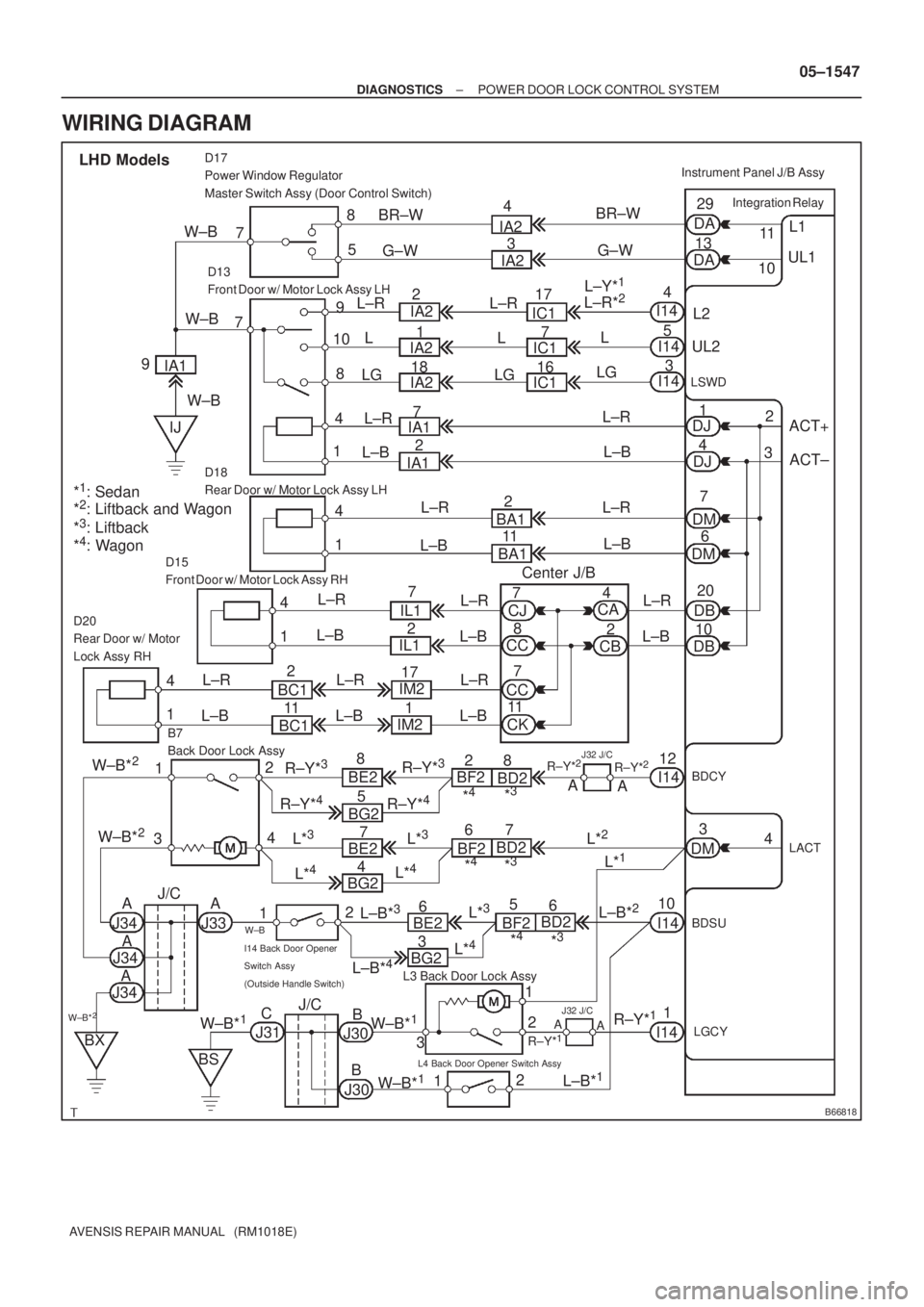
± DIAGNOSTICSPOWER DOOR LOCK CONTROL SYSTEM
05±1547
AVENSIS REPAIR MANUAL (RM1018E)
WIRING DIAGRAM
Page 1645 of 5135

B68159
17
DB
DCTY
KSW R B J/C
Combination Meter Assy
IC119
I14 11 DA Y
I14 22
P±B 12 1
W±B*
3
A1310
29*6
Buzzer
Meter ECU
20*
7
U1
Unlock Warning
Switch AssyIntegration Relay
B D9*
4
D10*5
Door Courtesy Lamp Switch
(Driver Side)
W±B
IC1
P
*
1: 1AZ±FSE
*2: 1AZ±FE, 1ZZ±FE, 3ZZ±FE
*
3: 1CD±FTV
*
4: LHD
*5: RHD
*
6: Except Automatic A/C
*7: Automatic A/CMPX2 Instrument Panel J/B
13
J10 J10CE CA1
5
R RIC2 IM1914
8 W±B*
5CF CA13
6
MPX1 P±B
C1014 1
A15
MPX±
MPX+
A13
A159*
6
10*7
P
P±B A/C Control
Assembly
E10 E9 E9212929
E10 E9 E9 202318ECM
*
1*1*2*3*2*3
*5*4
R*5
R*4
Center J/B
Center J/B
C10 13
PR
IPIL W±B*
4A
AJ16
IO W±B*
1,
2
R*5
W±B*5
05±1594
± DIAGNOSTICSKEY REMINDER WARNING SYSTEM
AVENSIS REPAIR MANUAL (RM1018E)
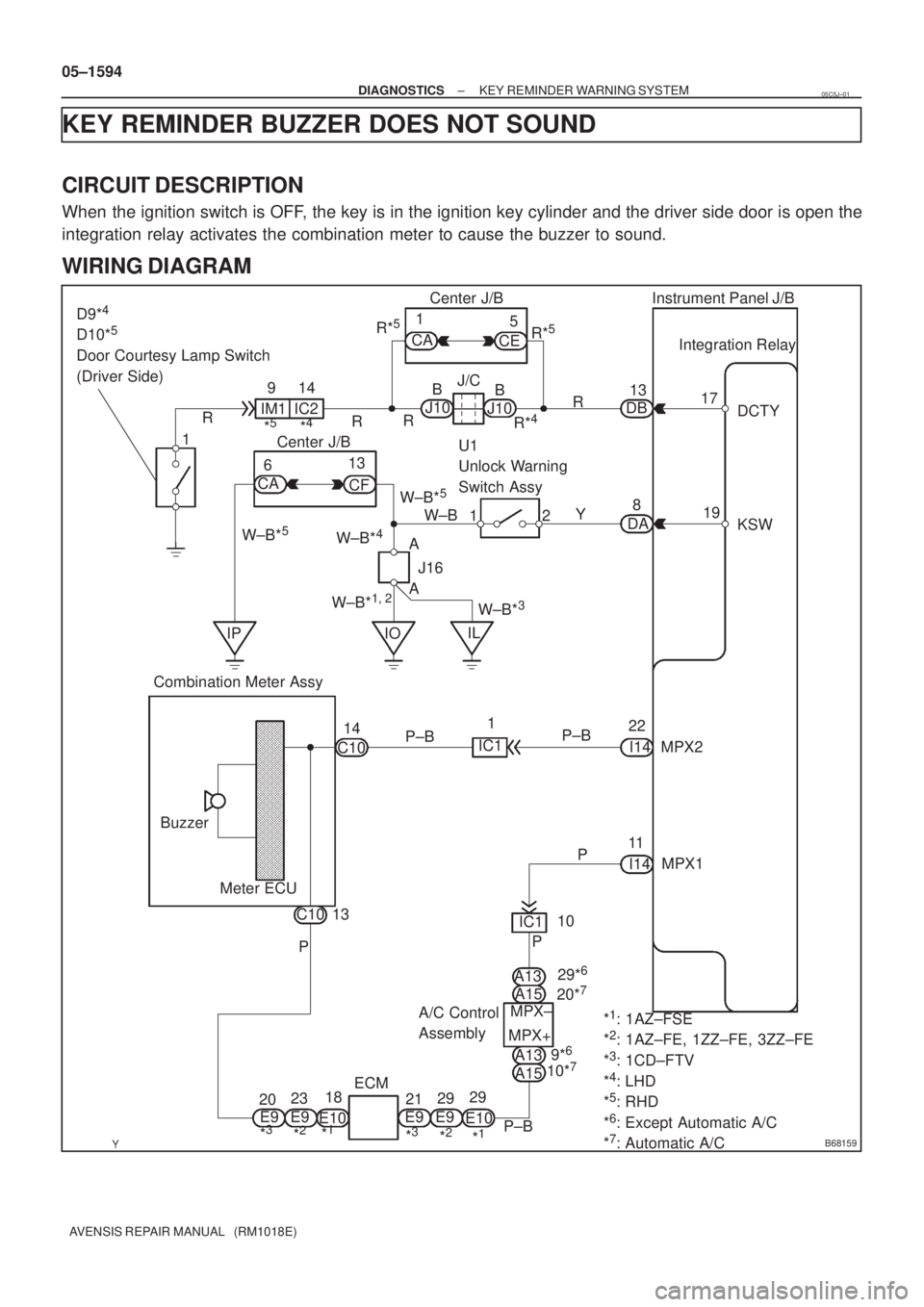
KEY REMINDER BUZZER DOES NOT SOUND
CIRCUIT DESCRIPTION
When the ignition switch is OFF, the key is in the ignition key cylinder and the driver side door is open the
integration relay activates the combination meter to cause the buzzer to sound.
WIRING DIAGRAM
05C5J±01
Page 1658 of 5135
B66772
Instrument Panel J/B Assy
Integration
Relay
FRLY 6
I14 LG
J11D15 T10
Turn Signal Flasher Relay
EHW8
To
Hazard Warning
Signal SwitchIC2
J25
*
1*2
J10 J24
*1*2
J10 J24
*
1*2
LG
LG
LGDDF
FB
*
1: LHD Models
*
2: RHD Models J/C 05±1584
± DIAGNOSTICSWIRELESS DOOR LOCK CONTROL SYSTEM
AVENSIS REPAIR MANUAL (RM1018E)
NO ANSWER±BACK (HAZARD WARNING LAMP)
CIRCUIT DESCRIPTION
If there is no answer±back of the hazard warning lamps although the wireless door lock/unlock function is
operating normally, there might be a malfunction in the hazard warning lamp signal that is output from the
integration relay.
WIRING DIAGRAM
05BNC±01
Page 1660 of 5135
B67694
IG
10 CK CA
Instrument Panel J/B AssyR±W
1 21
3
IG1 AM1
Battery B*
2
G±R
DH1
AM1T6
Theft Warning ECU Assy
Center J/B Assy
7
R±W
I13
Ignition Switch
Assy1G±Y
Main 3 3
4D 4BB±G*
1B±G*1
W*2
1 DA9
1 5 3 GAUGE1
IG1
Relay
ED1 DN DH 5 1DB
7
ALT
ALT Engine Room R/B No. 3
*
1: Gasoline
*2: 1CD±FTV1 B±L*
2
IJ W±B
21
21 Engine Room J/B No. 4
± DIAGNOSTICSTHEFT DETERRENT SYSTEM
05±1639
AVENSIS REPAIR MANUAL (RM1018E)
IGNITION SWITCH CIRCUIT
CIRCUIT DESCRIPTION
When the ignition switch is turned to the ON position, battery positive voltage is applied to terminal IG of the
theft warning ECU.
WIRING DIAGRAM
05BAD±01
Page 1663 of 5135
B67693
+B1
E W±R B±W
1A5
3DCCEngine Room R/B 1IP1
B*
2
BatteryJ/C
IPW±B
29 Center J/B 6T6
Theft Warning ECU Assy
CG 6J26 W±R
J27 6 Fuse Block
DOME
B±W
34A
4B B±G*
1
B±G*1B*2
3.0W Engine
Room R/B
No. 3CA W±B9
*
1: Gasoline
*2: 1CD±FTV 2 1
1 2
1
1FH
2
Engine
Room J/B
No. 4
± DIAGNOSTICSTHEFT DETERRENT SYSTEM
05±1637
AVENSIS REPAIR MANUAL (RM1018E)
ECU POWER SOURCE CIRCUIT
CIRCUIT DESCRIPTION
This circuit provides power to operate the theft warning ECU.
WIRING DIAGRAM
05BAC±01
Page 1665 of 5135

B67692
T6
Theft Warning ECU Assy
IND
25 W±B
1LSecurity A J16
J/C
18V F19
Rear Window Defogger
Switch Assy
(Security Indicator)
B67862
± DIAGNOSTICSTHEFT DETERRENT SYSTEM
05±1635
AVENSIS REPAIR MANUAL (RM1018E)
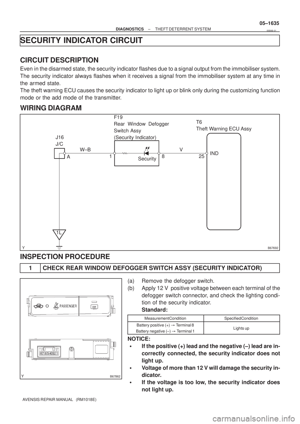
SECURITY INDICATOR CIRCUIT
CIRCUIT DESCRIPTION
Even in the disarmed state, the security indicator flashes due to a signal output from the immobiliser system.
The security indicator always flashes when it receives a signal from the immobiliser system at any time in
the armed state.
The theft warning ECU causes the security indicator to light up or blink only during the customizing function
mode or the add mode of the transmitter.
WIRING DIAGRAM
INSPECTION PROCEDURE
1 CHECK REAR WINDOW DEFOGGER SWITCH ASSY (SECURITY INDICATOR)
(a) Remove the defogger switch.
(b) Apply 12 V positive voltage between each terminal of the
defogger switch connector, and check the lighting condi-
tion of the security indicator.
Standard:
Measurement ConditionSpecified Condition
Battery positive (+) � Terminal 8
Battery negative (±) � Terminal 1Lights up
NOTICE:
�If the positive (+) lead and the negative (±) lead are in-
correctly connected, the security indicator does not
light up.
�Voltage of more than 12 V will damage the security in-
dicator.
�If the voltage is too low, the security indicator does
not light up.
05BAB±01
Page 1675 of 5135

B66227
E10
ECMT8
Transponder Key ECU Assy
IMI
IMO30*
1
27*2
29*1
26*2W GR
6
7EFIO
EFII
*1: 1CD±FTV
*2: Gasoline
± DIAGNOSTICSENGINE IMMOBILISER SYSTEM
05±1625
AVENSIS REPAIR MANUAL (RM1018E)
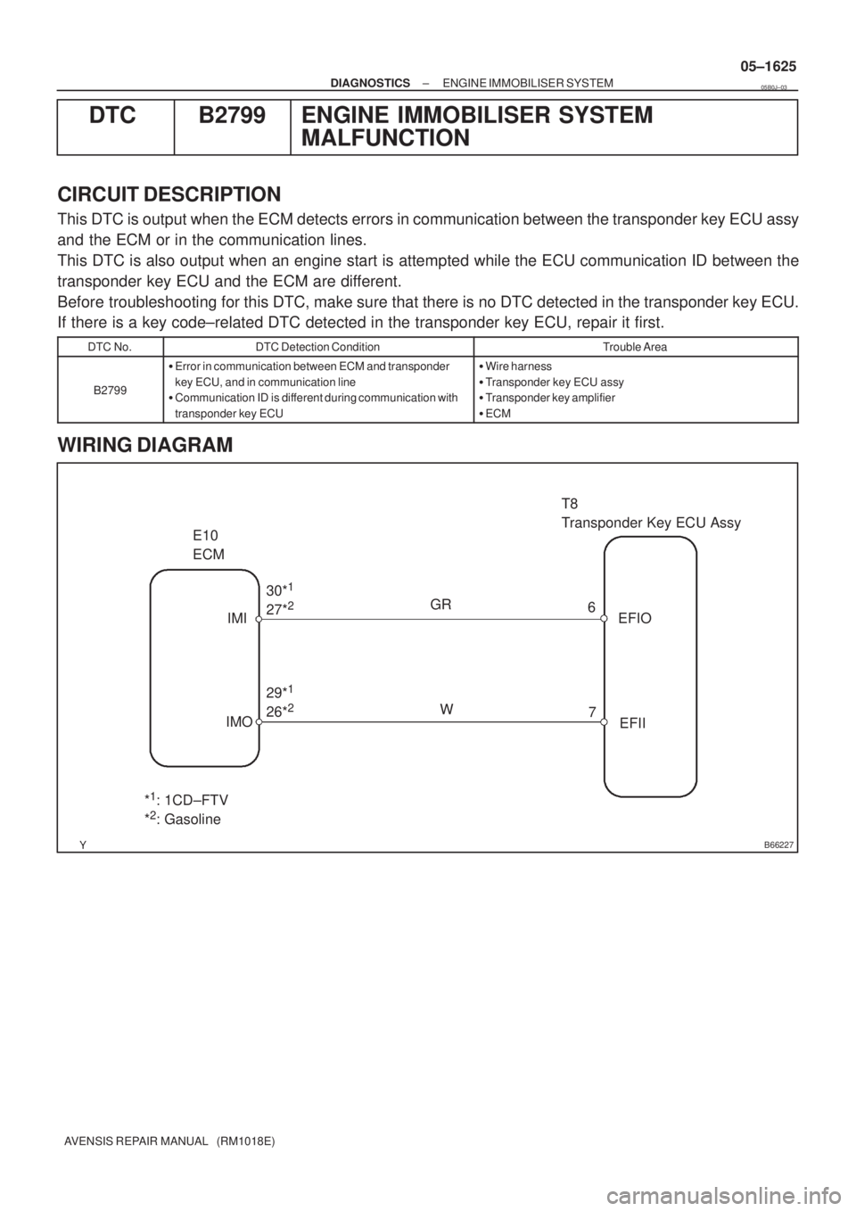
DTC B2799 ENGINE IMMOBILISER SYSTEM
MALFUNCTION
CIRCUIT DESCRIPTION
This DTC is output when the ECM detects errors in communication between the transponder key ECU assy
and the ECM or in the communication lines.
This DTC is also output when an engine start is attempted while the ECU communication ID between the
transponder key ECU and the ECM are different.
Before troubleshooting for this DTC, make sure that there is no DTC detected in the transponder key ECU.
If there is a key code±related DTC detected in the transponder key ECU, repair it first.
DTC No.DTC Detection ConditionTrouble Area
B2799
�Error in communication between ECM and transponder
key ECU, and in communication line
�Communication ID is different during communication with
transponder key ECU�Wire harness
�Transponder key ECU assy
�Transponder key amplifier
�ECM
WIRING DIAGRAM
05B0J±03