Page 1764 of 5135
05±1710
±
DIAGNOSTICS CRUISE CONTROL SYSTEM
AVENSIS REPAIR MANUAL (RM1018E)
DTC P0500/21 VEHICLE SPEED SENSOR ºAº
DTC P0503/23 VEHICLE SPEED SENSOR ºAº INTERMITTENT/ERRATIC/HIGH
CIRCUIT DESCRIPTION
See page 05±453. (1AZ±FSE) See page 05±640. (1CD±FTV)
DTC No.DTC Detection ConditionTrouble Area
P0500/21
The malfunction code is output when the vehicle speed signal
from the vehicle speed sensor is cut for 0.14 sec. or more
while cruise control is in operation.
�Combination meter
� Vehicle speed sensor
P0503/23
Momentary interruption and noise malfunction codes are output
when a rapid change of vehicle speed occurs while cruise
control is in operation.
Vehicle s eed sensor
�Vehicle speed sensor
� ECM
WIRING DIAGRAM
See page 05±453. (1AZ±FSE) See page 05±640. (1CD±FTV)
INSPECTION PROCEDURE
See page 05±453. (1AZ±FSE) See page 05±640. (1CD±FTV)
05C4Q±01
Page 1779 of 5135
B67809
Battery113
31 MPX1P
Theft Warning ECU Assy
E10 18
H 22
J/C
+B
W±B*
5
T6 I14
MainW±R*
5
AIC1BEAN
(EFI)
B*
3
POWER
EARTH
3
Instrument Panel J/B Assy
(Integration Relay)
ECMCombination Meter Assy
(Combination Meter ECU)
E9 E923 20
C10
BEAN
(BODY) 14
C10 P±B P±B
BEAN
(SECURITY) 15
C10 P±L*
4
MPX2
MPX
20
C11
C1017 J11 J26 J10
J26F F
F
W±R*
6
W±R
6
6
12DOME
B±W IE4
IP14*
5
5*6
B±W
1
1 2
1A
B±G*
1,
2
B±G*1,
2B*3
3
1
1 4B 4A
W±B*6
A
J16
J/CJ17
J/C
IK
IO*
1,
2,
5
*1: 1AZ±FSE
*2: 1AZ±FE, 1ZZ±FE, 3ZZ±FE
*
3: 1CD±FTV
*
4: w/ Theft Deterrent System
*5: LHD
*
6: RHD *
1*2*3
Engine Room R/BFuse Block Assy
Engine Room J/B No. 4*1,
2Engine Room R/B No. 3*3
DCC
1
AA
W±B*
6
W±BA
J15
J/C
IL*
3,
5
05±1694
± DIAGNOSTICSMULTIPLEX COMMUNICATION SYSTEM
AVENSIS REPAIR MANUAL (RM1018E)
WIRING DIAGRAM
Page 2921 of 5135
I35431
Burner Motor
Glow Plug
Surface Sensor
Temp. Control Sensor
Flame Sensor13
Power
Heater
ECU
Connector BTerminal L
of AlternatorBattery
Metering Pump
Fuse (20 A)
Vehicle Side SW 14
9
12
5
6
3
4
1
2R
BR
B±R
G
L±Y
L
Y
L±W5
1
6
2
7
3
8
4W±B
R±G
R±B Connector A
IG
W±R (*1)
Y±R (*2)
R±L (*1)
R±Y (*2)
*1: TMC Made
*2: TMUK Made 55±16
± HEATER & AIR CONDITIONERCOMBUSTION TYPE POWER HEATER SYSTEM
AVENSIS REPAIR MANUAL (RM1018E)
2. DESCRIPTION OF DISPLAY AND BUTTONS
(a) AF: Current Value Malfunction (Blinking at current failure)
Diag: DTC (Example: 064 Flame sensor break)
Memory Clear button: Deletion of faulty memory (Press both buttons together for longer than 2 se-
conds)
> Button: Scroll up of faulty memory (The past 5 codes can be stored.)
< Button: Scroll down of faulty memory (The past 5 codes can be stored.)
3. FAULTY MEMORY
(a) The ECU is able to store up to 5 pieces of faulty memory. If it is full, the new data is written over F5.
4. WIRING DIAGRAM
Page 2991 of 5135

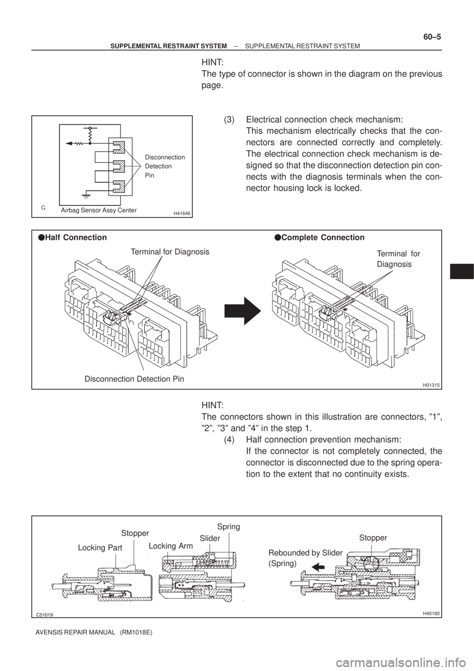
H41646
Disconnection
Detection
Pin
Airbag Sensor Assy Center
H01315
Terminal for Diagnosis
Disconnection Detection Pin �Half Connection�Complete Connection
Terminal for
Diagnosis
������H40180
Stopper
Locking PartSpring
Slider
Locking Arm
Rebounded by Slider
(Spring)Stopper
± SUPPLEMENTAL RESTRAINT SYSTEMSUPPLEMENTAL RESTRAINT SYSTEM
60±5
AVENSIS REPAIR MANUAL (RM1018E)
HINT:
The type of connector is shown in the diagram on the previous
page.
(3) Electrical connection check mechanism:
This mechanism electrically checks that the con-
nectors are connected correctly and completely.
The electrical connection check mechanism is de-
signed so that the disconnection detection pin con-
nects with the diagnosis terminals when the con-
nector housing lock is locked.
HINT:
The connectors shown in this illustration are connectors, º1º,
º2º, º3º and º4º in the step 1.
(4) Half connection prevention mechanism:
If the connector is not completely connected, the
connector is disconnected due to the spring opera-
tion to the extent that no continuity exists.
Page 3877 of 5135

05±174
±
DIAGNOSTICS SFI SYSTEM(1AZ±FE)
AVENSIS REPAIR MANUAL (RM1018E)
DTCP0011/59CAMSHAFT POSITION ºAº ±TIMING OVER± ADVANCED OR SYSTEM PERFORMANCE
(BANK 1)
DTCP0012/59CAMSHAFT POSITION ºAº ±TIMING OVER± RETARDED (BANK 1)
CIRCUIT DESCRIPTION
Refer to DTC P0010/39 on page 05±169.
DTC No.DTC Detection ConditionTrouble Area
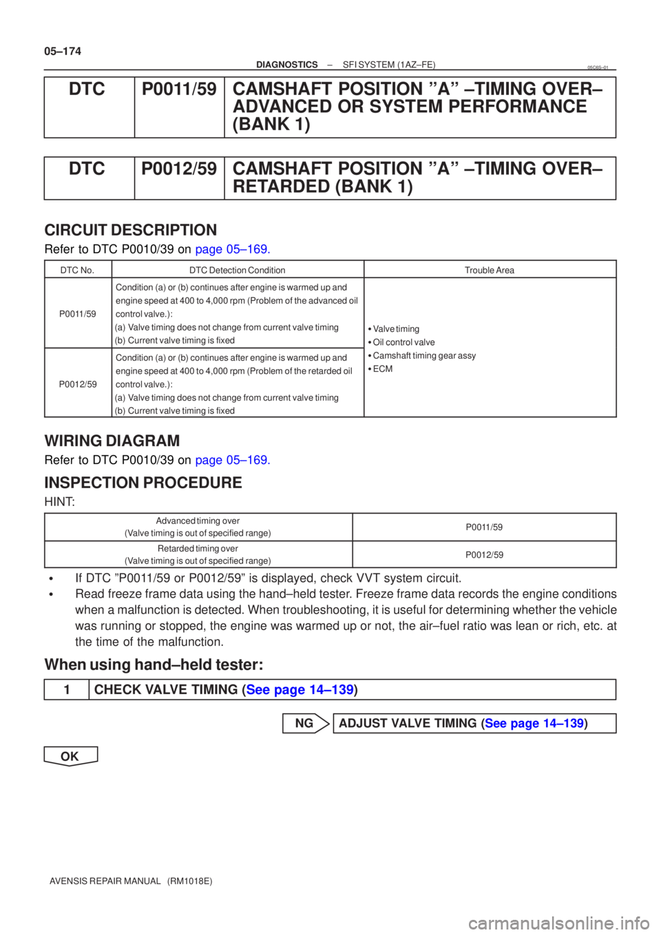
P0011/59
Condition (a) or (b) continues after engine is warmed up and
engine speed at 400 to 4,000 rpm (Problem of the advanced oil
control valve.):
(a)Valve timing does not change from current valve timing
(b)Current valve timing is fixed
� Valve timing
� Oil control valve
P0012/59
Condition (a) or (b) continues after engine is warmed up and
engine speed at 400 to 4,000 rpm (Problem of the retarded oil
control valve.):
(a)Valve timing does not change from current valve timing
(b)Current valve timing is fixed
Oil control valve
� Camshaft timing gear assy
� ECM
WIRING DIAGRAM
Refer to DTC P0010/39 on page 05±169.
INSPECTION PROCEDURE
HINT:
Advanced timing over
(Valve timing is out of specified range)P0011/59
Retarded timing over
(Valve timing is out of specified range)P0012/59
�If DTC ºP0011/59 or P0012/59º is displayed, check VVT system circuit.
�Read freeze frame data using the hand±held tester. Freeze frame data records the engine conditions
when a malfunction is detected. When troubleshooting, it is useful for deter\
mining whether the vehicle
was running or stopped, the engine was warmed up or not, the air±fuel ra\
tio was lean or rich, etc. at
the time of the malfunction.
When using hand±held tester:
1CHECK VALVE TIMING (See page 14±139)
NGADJUST VALVE TIMING (See page 14±139)
OK
05C6S±01
Page 3896 of 5135

05±122
±
DIAGNOSTICS SFI SYSTEM(1ZZ±FE/3ZZ±FE)
AVENSIS REPAIR MANUAL (RM1018E)
DTCP1656OCV CIRCUIT MALFUNCTION (BANK 1)
CIRCUIT DESCRIPTION
Refer to DTC P1349 on page 05±112.
DTC No.DTC Detecting ConditionTrouble Area
P1656Open or short in oil control valve (OCV) circuit
� Open or short in OCV circuit
� OCV
� ECM
WIRING DIAGRAM
Refer to DTC P1349 on page 05±112.
INSPECTION PROCEDURE
HINT:
Read freeze frame data using \f���� ����\b�\f��\f�
� Freeze frame data records the engine conditions when
a malfunction is detected. When troubleshooting, it is useful for determi\
ning whether the vehicle was running
or stopped, the engine was warmed up or not, the air±fuel ratio was lea\
n or rich, etc. at the time of the mal-
function.
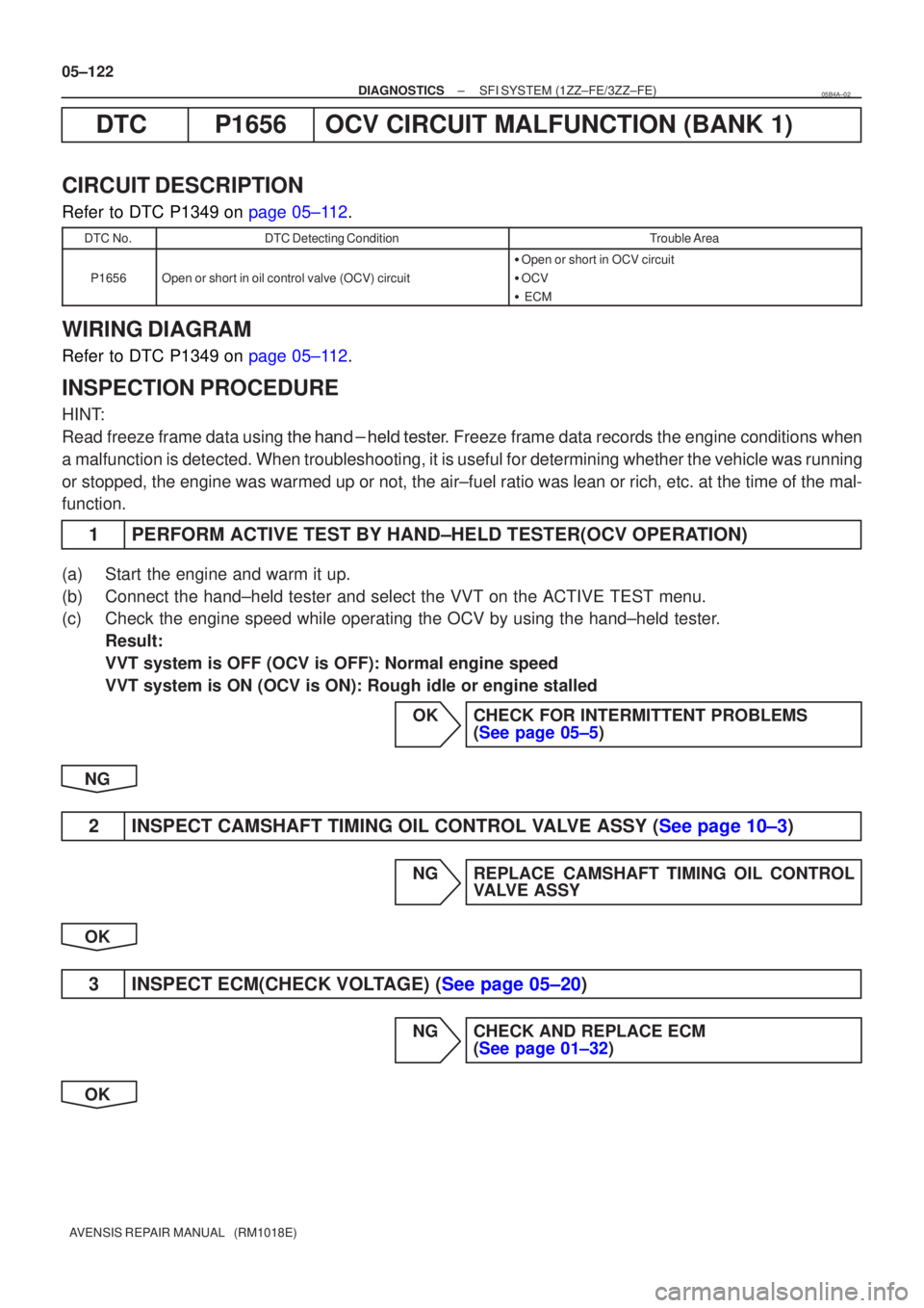
1PERFORM ACTIVE TEST BY HAND±HELD TESTER(OCV OPERATION)
(a)Start the engine and warm it up.
(b)Connect the hand±held tester and select the VVT on the ACTIVE TEST me\
nu.
(c)Check the engine speed while operating the OCV by using the hand±held\
tester. Result:
VVT system is OFF (OCV is OFF): Normal engine speed
VVT system is ON (OCV is ON): Rough idle or engine stalled
OKCHECK FOR INTERMITTENT PROBLEMS(See page 05±5)
NG
2INSPECT CAMSHAFT TIMING OIL CONTROL VALVE ASSY (See page 10±3)
NG REPLACE CAMSHAFT TIMING OIL CONTROL VALVE ASSY
OK
3INSPECT ECM(CHECK VOLTAGE) (See page 05±20)
NG CHECK AND REPLACE ECM (See page 01±32)
OK
05B4A±02
Page 3898 of 5135

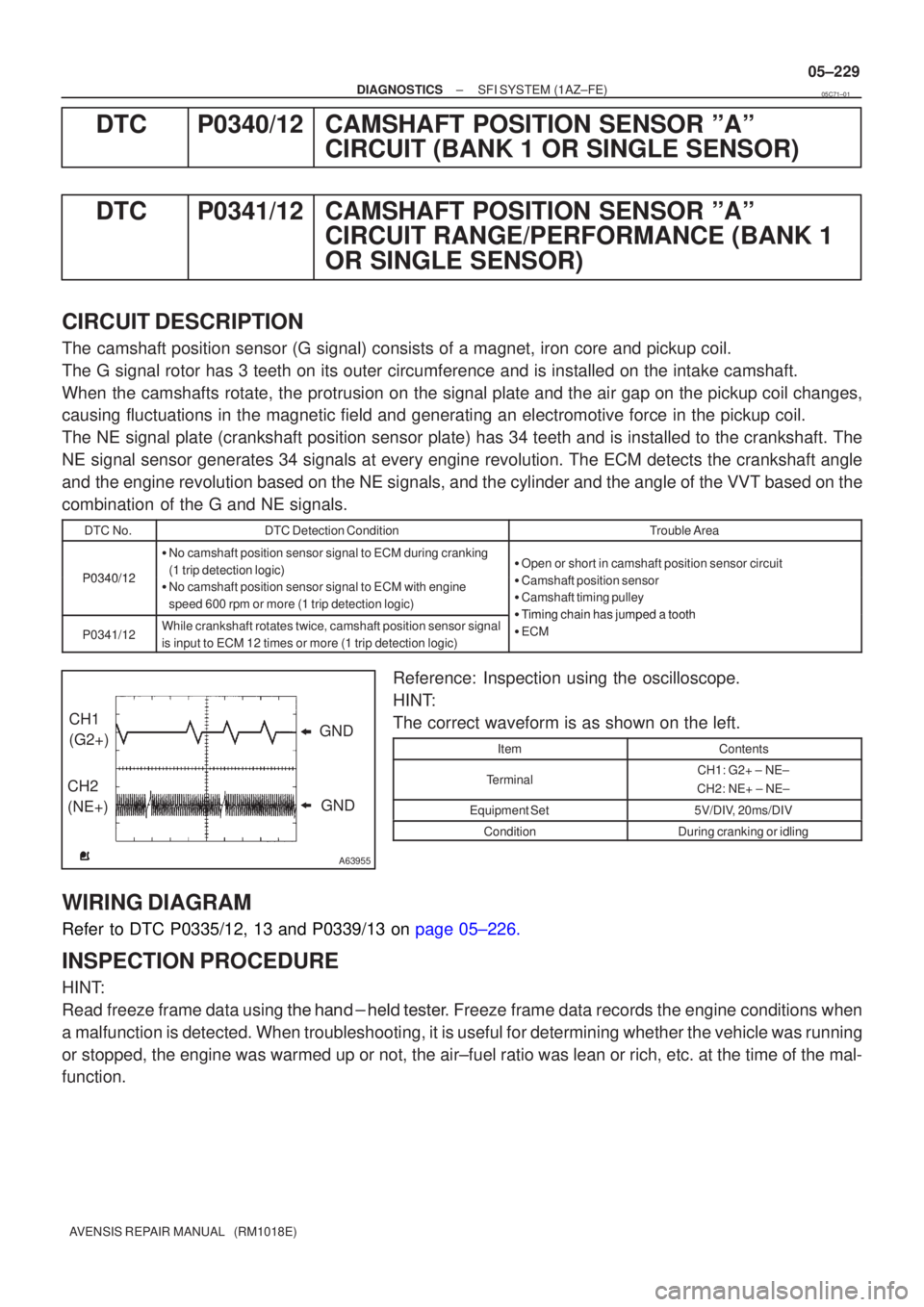
A63955
GND
CH1
(G2+)
CH2
(NE+) GND
±
DIAGNOSTICS SFI SYSTEM(1AZ±FE)
05±229
AVENSIS REPAIR MANUAL (RM1018E)
DTCP0340/12CAMSHAFT POSITION SENSOR ºAº
CIRCUIT (BANK 1 OR SINGLE SENSOR)
DTCP0341/12CAMSHAFT POSITION SENSOR ºAº CIRCUIT RANGE/PERFORMANCE (BANK 1
OR SINGLE SENSOR)
CIRCUIT DESCRIPTION
The camshaft position sensor (G signal) consists of a magnet, iron core a\
nd pickup coil.
The G signal rotor has 3 teeth on its outer circumference and is install\
ed on the intake camshaft.
When the camshafts rotate, the protrusion on the signal plate and the air gap on the pickup coil changes,
causing fluctuations in the magnetic field and generating an electromoti\
ve force in the pickup coil.
The NE signal plate (crankshaft position sensor plate) has 34 teeth an\
d is installed to the crankshaft. The
NE signal sensor generates 34 signals at every engine revolution. The EC\
M detects the crankshaft angle
and the engine revolution based on the NE signals, and the cylinder and the\
angle of the VVT based on the
combination of the G and NE signals.
DTC No.DTC Detection ConditionTrouble Area
P0340/12
�No camshaft position sensor signal to ECM during cranking
(1 trip detection logic)�Open or short in camshaft position sensor circuit
ChftitiP0340/12(1 tri detection logic)
�No camshaft position sensor signal to ECM with engine
speed 600 rpm or more (1 trip detection logic)�Camshaft position sensor
� Camshaft timing pulley
�Timingchainhasjumpedatooth
P0341/12While crankshaft rotates twice, camshaft position sensor signal
is input to ECM 12 times or more (1 trip detection logic)�Timing chain has jumped a tooth
�ECM
Reference: Inspection using the oscilloscope.
HINT:
The correct waveform is as shown on the left.
ItemContents
TerminalCH1: G2+ ± NE±
CH2: NE+ ± NE±
Equipment Set5V/DIV, 20ms/DIV
ConditionDuring cranking or idling
WIRING DIAGRAM
Refer to DTC P0335/12, 13 and P0339/13 on page 05±226.
INSPECTION PROCEDURE
HINT:
Read freeze frame data using \f�� �� ����\b� \f��\f�
� Freeze frame data records the engine conditions when
a malfunction is detected. When troubleshooting, it is useful for determi\
ning whether the vehicle was running
or stopped, the engine was warmed up or not, the air±fuel ratio was lea\
n or rich, etc. at the time of the mal-
function.
05C71±01
Page 3901 of 5135
±
DIAGNOSTICS SFI SYSTEM(1ZZ±FE/3ZZ±FE)
05±111
AVENSIS REPAIR MANUAL (RM1018E)
DTCP1346VVT SENSOR/CAMSHAFT POSITION
SENSOR CIRCUIT RANGE/PERFORMANCE
PROBLEM (BANK 1)
CIRCUIT DESCRIPTION
Refer to DTC P0335 on page 05±84
DTC No.Detection ItemTrouble Area
P1346Deviation in crankshaft position sensor signal and camshaft
position sensor signal (2 trip detection logic)�Mechanical system (Timing chain has jumped a tooth, chain
stretched)
� ECM
WIRING DIAGRAM
Refer to DTC P0335 on page 05±84
INSPECTION PROCEDURE
HINT:
Read freeze frame data using the hand±held tester. Freeze frame data records the engine conditions when
the malfunction is detected. When troubleshooting, it is useful for determining whether the vehicle was run-
ning or stopped, the engine was warmed up or not, the air±fuel ratio \
was lean or rich, etc. at the time of the
malfunction.
1CHECK VALVE TIMING (See page 14±49)
NGADJUST VALVE TIMING(See page 14±49)
OK
CHECK AND REPLACE ECM (See page 01±32)
0506C±04