Page 147 of 5135
030KB±05
± SERVICE SPECIFICATIONSDRIVE SHAFT / PROPELLER SHAFT / AXLE
03±39
AVENSIS REPAIR MANUAL (RM1018E)
DRIVE SHAFT / PROPELLER SHAFT / AXLE
SERVICE DATA
Front axle hub bearing BacklashMaximum: 0.05 mm (0.0020 in.)
Front axle hub sub±assy DeviationMaximum: 0.05 mm (0.0020 in.)
Rear axle hub & bearing assy Backlash
DeviationMaximum: 0.05 mm (0.0020 in.)
Maximum: 0.07 mm (0.0028 in.)
Page 417 of 5135
05CDV±01
A76858
Ignition Coil Assy
Camshaft Position Sensor VSV for EVAP
Combination Meter
DLC3
VSV for Intake Air Control ValveFuel Pump ECM
Knock Sensor Camshaft Timing Oil Control Valve
(OCV)
Injector
Crankshaft Position
Sensor
Park/Neutral Position Switch
(Only for A/T Models)Engine Coolant
Temperature Sensor
Mass Air Flow Meter
Throttle Body Assy
Accelerator Pedal Assy
Heated Oxygen Sensor
(Bank 2 Sensor 2)
Circuit Opening Relay
Heated Oxygen Sensor
(Bank 1 Sensor 2)
Heated Oxygen Sensor
(Bank 2 Sensor 1)
Heated Oxygen Sensor
(Bank 1 Sensor 1)
Manifold Absolute Pressure Sensor
Fuel Pump (For High Pressure)
Engine Room R/B No. 1Engine Room R/B No. 4Injector Driver (EDU)
Brake Booster
Pressure Sensor
Fuel Pressure Sensor
(For Low Pressure)
± DIAGNOSTICSSFI SYSTEM (1AZ±FSE)
05±317
AVENSIS REPAIR MANUAL (RM1018E)
LOCATION
Page 500 of 5135
05±328
±
DIAGNOSTICS SFI SYSTEM(1AZ±FSE)
AVENSIS REPAIR MANUAL (RM1018E)
9REPLACE CAMSHAFT TIMING GEAR ASSY (See page 14±240)
GO
10CHECK BLOCKAGE(OCV, OIL CHECK VALVE AND OIL HOLE)
NGREPAIR OR REPLACE
OK
11CHECK IF DTC OUTPUTS REOCCUR
(a)Clear the DTC. (1)Operating the hand±held tester to erase the codes, or disconnecting the batter\
y terminal or the
EFI and ETCS fuses for 60 seconds or more.
(b)Start the engine and warm it up.
(c)Drive the vehicle around for 10 minutes or more.
(d)Read output DTC using the hand±held tester.
Standard: No DTC output.
HINT:
*: DTCs P0011 or P0012 is output when a foreign object in engine oil is caught in so\
me part of the system.
These codes will stay registered even if the system returns to normal after a\
short time. These foreign objects
are then captured by the oil filter, thus eliminating the source of the problem.
OKVVT SYSTEM OK
NG
CHECK AND REPLACE ECM (See page 01±32)
Page 515 of 5135

± DIAGNOSTICSSFI SYSTEM (1AZ±FSE)
05±415
AVENSIS REPAIR MANUAL (RM1018E)
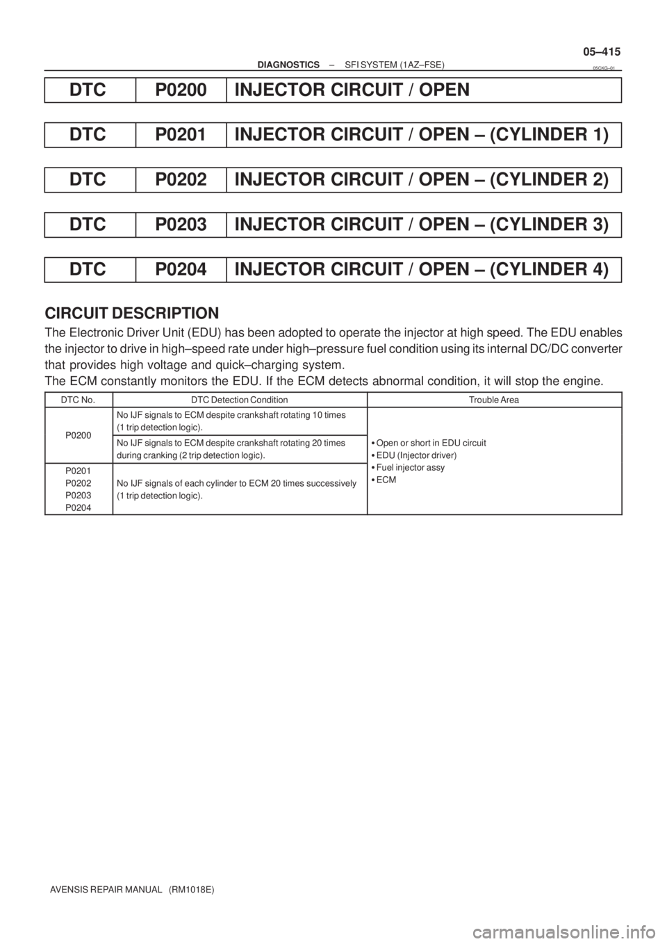
DTC P0200 INJECTOR CIRCUIT / OPEN
DTC P0201 INJECTOR CIRCUIT / OPEN ± (CYLINDER 1)
DTC P0202 INJECTOR CIRCUIT / OPEN ± (CYLINDER 2)
DTC P0203 INJECTOR CIRCUIT / OPEN ± (CYLINDER 3)
DTC P0204 INJECTOR CIRCUIT / OPEN ± (CYLINDER 4)
CIRCUIT DESCRIPTION
The Electronic Driver Unit (EDU) has been adopted to operate the injector at high speed. The EDU enables
the injector to drive in high±speed rate under high±pressure fuel condition using its internal DC/DC converter
that provides high voltage and quick±charging system.
The ECM constantly monitors the EDU. If the ECM detects abnormal condition, it will stop the engine.
DTC No.DTC Detection ConditionTrouble Area
P0200
No IJF signals to ECM despite crankshaft rotating 10 times
(1 trip detection logic).
P0200No IJF signals to ECM despite crankshaft rotating 20 times
during cranking (2 trip detection logic).�Open or short in EDU circuit
�EDU (Injector driver)
P0201
P0202
P0203
P0204
No IJF signals of each cylinder to ECM 20 times successively
(1 trip detection logic).
(j )
�Fuel injector assy
�ECM
05CKG±01
Page 616 of 5135

A76876
ECM
J13G
FP+ 6
R
E12
D(Shielded)
J13 E
J12 E J12D
BRBR
EEJ/C21 S3
Fuel Pump
(High Pressure)
(Spill Valve)
G
FP± 3
E12
(Shielded) BR
± DIAGNOSTICSSFI SYSTEM (1AZ±FSE)
05±477
AVENSIS REPAIR MANUAL (RM1018E)
DTC P1235 HIGH PRESSURE FUEL PUMP CIRCUIT
CIRCUIT DESCRIPTION
The fuel pump (high pressure) is an electronically controlled plunger type fuel pump (high pressure) which
is driven by the cam provided on the intake cam shaft rear end on the cylinder head.
The fuel pump (high pressure) increases the pressure of the fuel fed from the fuel pump (low pressure) in
the fuel tank at 8 to 13 MPa (81.6 to 132.6 kgf/cm
2, 1,160 to 1,885 psi) according to the operating condition,
and it feeds the fuel to the fuel delivery pipe.
DTC No.DTC Detection conditionTrouble Area
O h ti f l (hi h ) i itf 1�Open or short in fuel pump (high pressure)
P1235Open or short in fuel pump (high pressure) circuit for 1sec. or
more
�Oen or short in fuel um (high ressure)
�Fuel pump (high pressure)P1235moreFuel um (high ressure)
�ECM
WIRING DIAGRAM
INSPECTION PROCEDURE
HINT:
Read freeze frame data using hand±held tester. Freeze frame data records the engine conditions when the
malfunction is detected. When troubleshooting, it is useful for determining whether the vehicle was running
or stopped, the engine was warmed up or not, the air±fuel ratio was lean or rich, etc. at the time of the mal-
function.
05CK4±01
Page 920 of 5135
![TOYOTA AVENSIS 2005 Service Repair Manual 05±868± DIAGNOSTICSELECTRONIC CONTROLLED AUTOMATIC
TRANSAXLE [ECT] (U241E(1AZ±FE))
AVENSIS REPAIR MANUAL (RM1018E)
4. DATA LIST
HINT:
According to the DATA LIST displayed by the hand±held tester TOYOTA AVENSIS 2005 Service Repair Manual 05±868± DIAGNOSTICSELECTRONIC CONTROLLED AUTOMATIC
TRANSAXLE [ECT] (U241E(1AZ±FE))
AVENSIS REPAIR MANUAL (RM1018E)
4. DATA LIST
HINT:
According to the DATA LIST displayed by the hand±held tester](/manual-img/14/57441/w960_57441-919.png)
05±868± DIAGNOSTICSELECTRONIC CONTROLLED AUTOMATIC
TRANSAXLE [ECT] (U241E(1AZ±FE))
AVENSIS REPAIR MANUAL (RM1018E)
4. DATA LIST
HINT:
According to the DATA LIST displayed by the hand±held tester, you can read the value of the switch, sensor,
actuator and so on without parts removal. Reading the DATA LIST as the first step of troubleshooting is one
of the methods to shorten the work time.
(a) Warm up the engine.
(b) Turn the ignition switch OFF.
(c) Connect the hand±held tester to the DLC3.
(d) Turn the ignition switch ON.
(e) According to the display on tester, read the ºDATA LISTº.
ItemMeasurement Item/
Display (Range)Normal ConditionDiagnostic Note
STOP LIGHT SWStop light SW Status/
ON or OFF�Brake Pedal is depressed: ON
�Brake Pedal is released: OFF�
SHIFTActual Gear Position/
1st, 2nd, 3rd, 4th (O/D)Shift lever Range is;
�D: 1st, 2nd, 3rd or 4th (O/D)�
SPD (NC)Counter Gear Speed
display: 50 r/minD Range is warmed up,4th (O/D);
Same as input shaft speed�
LOCK UP SOLLock Up Solenoid Status/
ON or OFF�Lock Up: ON
�Except Lock Up: OFF�
KICKDOWN SWKick down SW Status/
ON or OFF
�Accelerator Pedal is depressed:
ON
�Accelerator Pedal is released:
OFF
�
PNP SW [NSW]PNP SW Status/
ON or OFFShift lever range is;
P or N: ON
Except P or N: OFF
The shift lever range and these
REVERSEPNP SW Status/
ON or OFFShift lever range is;
R: ON
Except R: OFFThe shift lever range and these
values are different, there are fail-
ures of the PNP switch or shift
cable adjustment
DRIVEPNP SW Status/
ON or OFFShift lever range is;
D and 3: ON
Except D and 3: OFFcable adjustment.
SOLENOID (SLT)Shift Solenoid SLT Status/
ON or OFFIG SW ON: ON�
AT FLUID TEMP
ATF Temp. Sensor Value/
min.: ±40�C (±40�F)
max.: 215�C (419�F)80�C (176�F)
(After Stall Test)If the value is º±40�C (±40�F)º or
º215�C (419�F)º, ATF temp. sen-
sor circuit is opened or shorted.
Page 1910 of 5135

110UA±01
A15950
±
FUEL INJECTION OR SUPPLY PUMP ASSY(1CD±FTV)
11±69
AVENSIS REPAIR MANUAL (RM1018E)
REPLACEMENT
1.REMOVE FRONT WHEEL RH
2.DRAIN ENGINE COOLANT(See page 16±44)
3.REMOVE ENGINE UNDER COVER SUB±ASSY NO.1
4.REMOVE ENGINE UNDER COVER RH
5.REMOVE RADIATOR SUPPORT OPENING COVER
6.REMOVE ENGINE ROOM COVER SIDE
7.REMOVE AIR CLEANER ASSY (See page 11±60)
8.REMOVE ENGINE COVER NO.1
(a)Remove the 5 nuts and the engine cover.
9.REMOVE RADIATOR RESERVE TANK ASSY(See page 16±50)
10.DISCONNECT RADIATOR HOSE OUTLET
(a)Disconnect the radiator hose outlet from the water inlet.
11.REMOVE V (COOLER COMPRESSOR TO CRANKSHAFT PULLEY) BELT NO.1
(See page 14±269)
12.REMOVE GENERATOR V BELT (See page 14±269)
13.REMOVE INJECTOR DRIVER
(a)Remove the 2 nuts which are used to secure the injector driver.
(b)Disconnect the injector driver connector and the harness clamp.
(c)Remove the injector driver.
14.REMOVE ENGINE MOUNTING INSULATOR SUB±ASSY RH(See page 14±307)
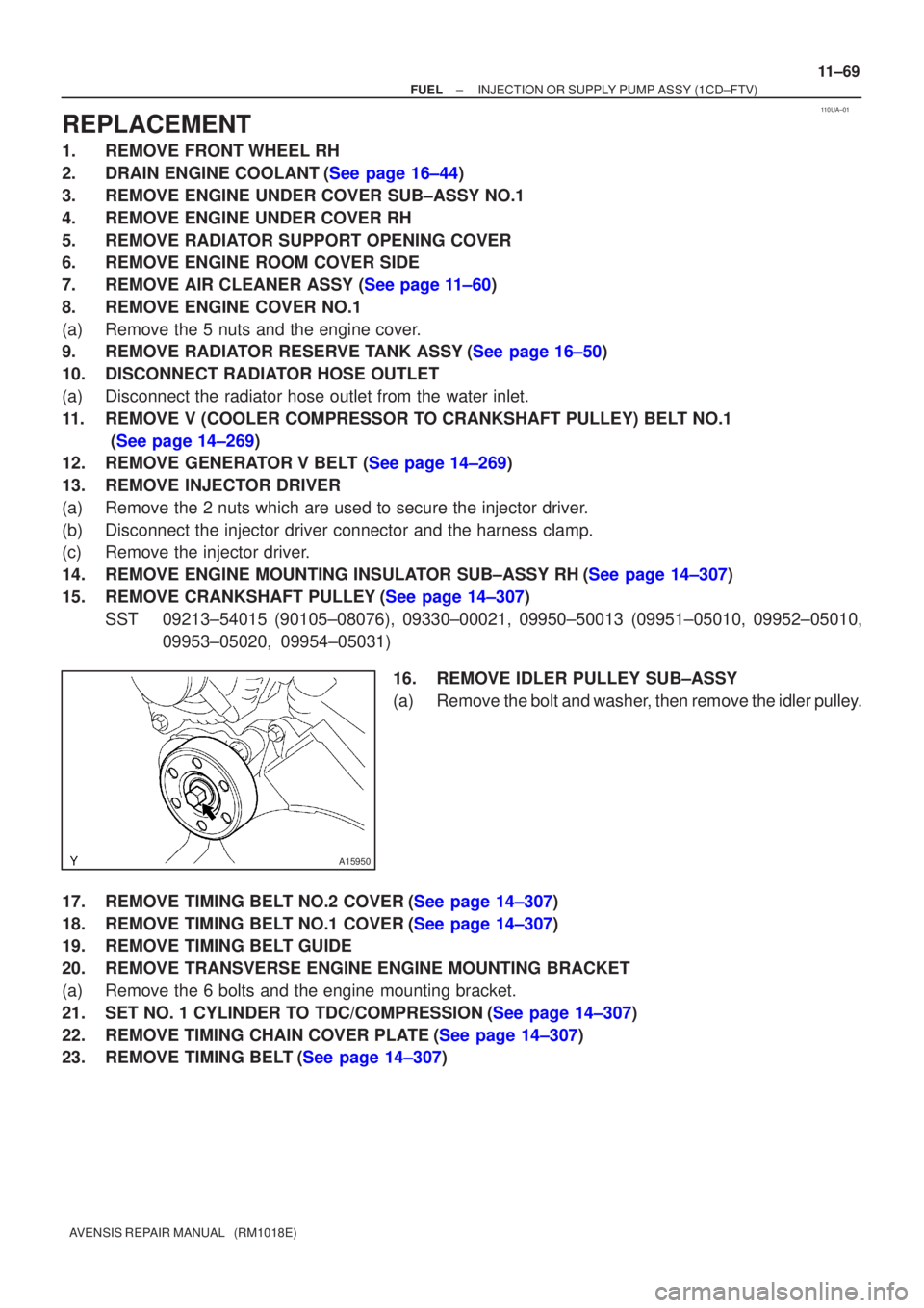
15.REMOVE CRANKSHAFT PULLEY(See page 14±307)
SST09213±54015 (90105±08076), 09330±00021, 09950±50013 (0995\
1±05010, 09952±05010, 09953±05020, 09954±05031)
16.REMOVE IDLER PULLEY SUB±ASSY
(a)Remove the bolt and washer, then remove the idler pulley.
17.REMOVE TIMING BELT NO.2 COVER(See page 14±307)
18.REMOVE TIMING BELT NO.1 COVER(See page 14±307)
19. REMOVE TIMING BELT GUIDE
20. REMOVE TRANSVERSE ENGINE ENGINE MOUNTING BRACKET
(a) Remove the 6 bolts and the engine mounting bracket.
21.SET NO. 1 CYLINDER TO TDC/COMPRESSION(See page 14±307)
22.REMOVE TIMING CHAIN COVER PLATE(See page 14±307)
23.REMOVE TIMING BELT(See page 14±307)
Page 1916 of 5135

±
FUEL INJECTION OR SUPPLY PUMP ASSY (1CD±FTV)
11±75
AVENSIS REPAIR MANUAL (RM1018E)
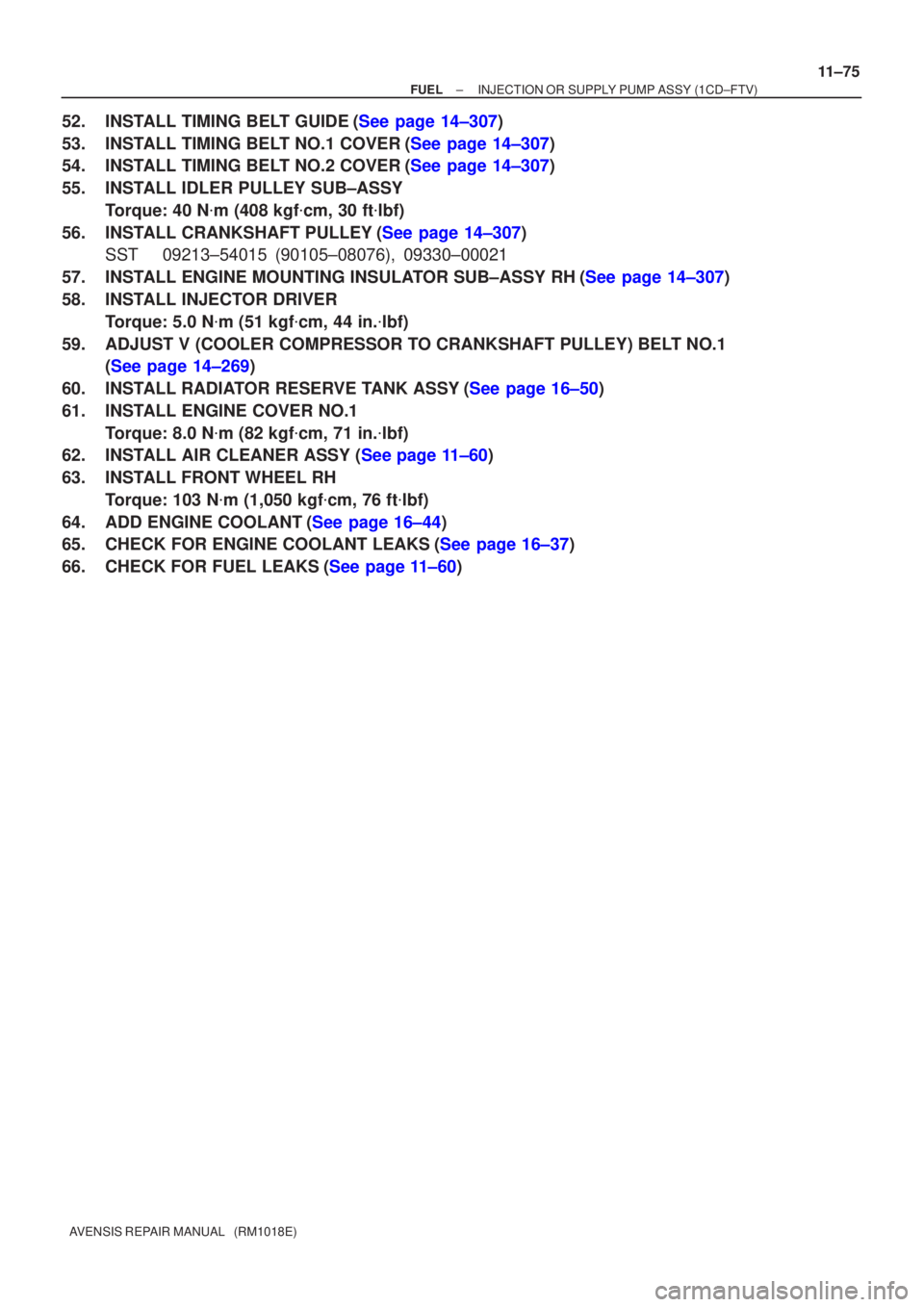
52.INSTALL TIMING BELT GUIDE(See page 14±307)
53.INSTALL TIMING BELT NO.1 COVER(See page 14±307)
54.INSTALL TIMING BELT NO.2 COVER(See page 14±307)
55. INSTALL IDLER PULLEY SUB±ASSY
Torque: 40 N �m (408 kgf �cm, 30 ft �lbf)
56.INSTALL CRANKSHAFT PULLEY(See page 14±307) SST 09213±54015 (90105±08076), 09330±00021
57.INSTALL ENGINE MOUNTING INSULATOR SUB±ASSY RH(See page 14±307)
58. INSTALL INJECTOR DRIVER Torque: 5.0 N �m (51 kgf �cm, 44 in. �lbf)
59. ADJUST V (COOLER COMPRESSOR TO CRANKSHAFT PULLEY) BELT NO.1 (See page 14±269)
60.INSTALL RADIATOR RESERVE TANK ASSY(See page 16±50)
61. INSTALL ENGINE COVER NO.1 Torque: 8.0 N �m (82 kgf �cm, 71 in. �lbf)
62.INSTALL AIR CLEANER ASSY (See page 11±60)
63. INSTALL FRONT WHEEL RH
Torque: 103 N �m (1,050 kgf �cm, 76 ft �lbf)
64.ADD ENGINE COOLANT(See page 16±44)
65.CHECK FOR ENGINE COOLANT LEAKS(See page 16±37)
66.CHECK FOR FUEL LEAKS(See page 11±60)