Page 1917 of 5135
110U9±01
A79435
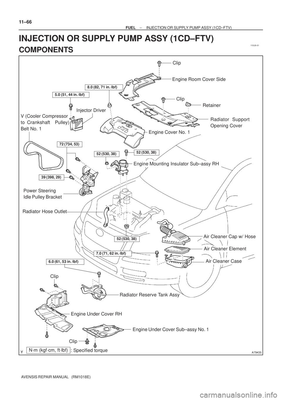
Air Cleaner Cap w/ Hose
Air Cleaner Element
Air Cleaner Case
7.0 (71, 62 in.�lbf)
N´m (kgf´cm, ft´lbf)
: Specified torque
Radiator Hose Outlet
Clip
Engine Room Cover Side
Clip
Retainer
Radiator Support
Opening Cover
8.0 (82, 71 in.�lbf)
5.0 (51, 44 in.�lbf)
V (Cooler Compressor
to Crankshaft Pulley)
Belt No. 1
Injector Driver
72 (734, 53)
52 (530, 38)52 (530, 38)
Engine Cover No. 1
Engine Mounting Insulator Sub±assy RH
39 (398, 29)
Power Steering
Idle Pulley Bracket
52 (530, 38)
Clip
Engine Under Cover RH
Engine Under Cover Sub±assy No. 1
Clip
Radiator Reserve Tank Assy
6.0 (61, 53 in.�lbf)
11±66
± FUELINJECTION OR SUPPLY PUMP ASSY (1CD±FTV)
AVENSIS REPAIR MANUAL (RM1018E)
INJECTION OR SUPPLY PUMP ASSY (1CD±FTV)
COMPONENTS
Page 1982 of 5135
A62180
Disconnect
Hook
Pin Turn
A62181
Plunger
Turn
Push
A11858
A64005
14±16
± ENGINE MECHANICALVALVE CLEARANCE (1ZZ±FE/3ZZ±FE)
AVENSIS REPAIR MANUAL (RM1018E)
(3) Turn the crankshaft counterclockwise, and take the
hook off the knock pin to release the plunger.
(4) Turn the crankshaft clockwise, and check that the
plunger is extended.
HINT:
If the plunger does not be extended, press the slipper into the
chain tensioner using a screwdriver so that the hook is took off
from the knock pin and let the plunger can be extended.
16. INSTALL V±RIBBED BELT TENSIONER ASSY
(a) Install the V±ribbed belt tensioner with the nut and bolt.
Torque:
29 N�m (296 kgf�cm, 21 ft�lbf) for Nut
69 N�m (704 kgf�cm, 51 ft�lbf) for Bolt
17. INSTALL ENGINE MOUNTING INSULATOR
SUB±ASSY RH
(a) Install the engine mounting insulator with the 4 bolts and
2 nuts.
Torque: 52 N�m (530 kgf�cm, 38 ft�lbf)
Page 2021 of 5135

14±73
AVENSIS REPAIR MANUAL (RM1018E)
(2)Apply engine oil to the chai")
A62178
Push
A62180
DisconnectHook
PinTurn
A62181
Plunger
Turn
Push
A11858
A64005
±
ENGINE MECHANICAL CAMSHAFT(1ZZ±FE/3ZZ±FE)
14±73
AVENSIS REPAIR MANUAL (RM1018E)
(2)Apply engine oil to the chain tensioner and install it
with the 2 nuts.
Torque: 9.0 N �m (92 kgf �cm, 80 in �lbf)
NOTICE:
If the hook released the plunger during installation, re±
hook the plunger by the hook to fix it.
(3)Turn the crankshaft counter clockwise, and take thehook off the knock pin to release the plunger.
(4)Turn the crankshaft clockwise, and check that the plunger is extended.
HINT:
If the plunger does not be extended, press the slipper into the
chain tensioner using a screwdriver so that the hook is took off
from the knock pin and let the plunger can be extended.
19.ADJUST VALVE CLEARANCE(See page 14±6)
20. INSTALL V±RIBBED BELT TENSIONER ASSY
(a) Install the V±ribbed belt tensioner with the nut and bolt. Torque:
29 N�m (296 kgf �cm, 21 ft �lbf) for Nut
69 N �m (704 kgf �cm, 51 ft �lbf) for Bolt
21. INSTALL ENGINE MOUNTING INSULATOR SUB±ASSY RH
(a) Install the engine mounting insulator with the 4 bolts and
2 nuts.
Torque: 52 N �m (530 kgf �cm, 38 ft �lbf)
Page 2031 of 5135

AVENSIS REPAIR MANUAL (RM1018E)
20. REMOVE TRANSVERSE ENGINE ENGINE
MOUNTING BRACKET
(a) Remove t")
A12816
A76692
A62178
Push
A10076
A30848
14±52
± ENGINE MECHANICALCHAIN SUB±ASSY (1ZZ±FE/3ZZ±FE)
AVENSIS REPAIR MANUAL (RM1018E)
20. REMOVE TRANSVERSE ENGINE ENGINE
MOUNTING BRACKET
(a) Remove the 3 bolts and the transverse engine engine
mounting bracket.
21. REMOVE CRANKSHAFT POSITION SENSOR
(a) Remove the 2 bolts which are used to secure the crank-
shaft position sensor.
22. REMOVE CHAIN TENSIONER ASSY NO.1
(a) Remove the 2 nuts and the chain tensioner.
NOTICE:
Do not revolve the crankshaft without the chain tensioner.
23. REMOVE TIMING CHAIN OR BELT COVER
SUB±ASSY
(a) Remove the 11 bolts and nuts.
(b) Using a torx wrench socket (E8), remove the stud bolt.
(c) Remove the timing chain cover by prying between the cyl-
inder head and the cylinder block with a screwdriver.
NOTICE:
Be careful not to damage the timing chain cover, the cylin-
der head and the cylinder block.
24. REMOVE TIMING GEAR COVER OIL SEAL
(a) Using a screwdriver, remove the oil seal.
25. REMOVE CRANKSHAFT POSITION SENSOR PLATE
NO.1
26. REMOVE CHAIN TENSIONER SLIPPER
(a) Remove the bolt and the chain tensioner slipper.
Page 2032 of 5135

14±53
AVENSIS REPAIR MANUAL (RM1018E)
27. REMOVE CHAIN SUB�")
A30857
A10079
A62170
Set KeyUpward
A62171
Yellow
Color Link
Timing Mark
A62172
SST
± ENGINE MECHANICALCHAIN SUB±ASSY (1ZZ±FE/3ZZ±FE)
14±53
AVENSIS REPAIR MANUAL (RM1018E)
27. REMOVE CHAIN SUB±ASSY
(a) Remove the timing chain with the crankshaft timing gear
by plying it using screwdrivers as shown in the illustration.
NOTICE:
�Put shop rag to protect the engine.
�In case of revolving the camshafts with the chain off
the sprockets, turn the crankshaft 1/4 revolution
counterclockwise for valves not to touch the pistons.
28. INSTALL CHAIN SUB±ASSY
(a) Set No. 1 cylinder to TDC/compression.
(1) Turn the camshafts with a wrench and align the
point marks of the camshaft timing sprockets.
(2) Using a crankshaft pulley bolt, turn the crankshaft
and set the set key on the crankshaft upward.
(b) Install the timing chain to the crankshaft timing sprocket
with the yellow color link aligned with the timing mark on
the crankshaft timing sprocket.
HINT:
Three yellow color links are on the chain.
(c) Using SST, install the crankshaft timing sprocket.
SST 09223±22010
Page 2036 of 5135

14±57
AVENSIS REPAIR MANUAL (RM1018E)
38. INSTALL CRANKS")
A62837SST
A62180
Disconnect
Hook
Pin Turn
A62181
Plunger
Turn
Push
A62182
Seal Packing
± ENGINE MECHANICALCHAIN SUB±ASSY (1ZZ±FE/3ZZ±FE)
14±57
AVENSIS REPAIR MANUAL (RM1018E)
38. INSTALL CRANKSHAFT PULLEY
(a) Align the keyway of the pulley with the key located on the
crankshaft, and slide the pulley into place.
(b) Using SST, install the crankshaft pulley bolt.
SST 09960±10010 (09962±01000, 09963±01000)
Torque: 138 N�m (1,407 kgf�cm, 102 ft�lbf)
(c) Turn the crankshaft counterclockwise, and take the hook
off the knock pin to release the plunger.
(d) Turn the crankshaft clockwise, and check that the plunger
is extended.
HINT:
If the plunger does not be extended, press the slipper into the
chain tensioner using a screwdriver so that the hook is took off
from the knock pin and let the plunger can be extended.
39. INSTALL CYLINDER HEAD COVER SUB±ASSY
(a) Remove any old pacing (FIPG) material.
(b) Apply seal packing to the 2 locations as shown in the il-
lustration.
Seal packing: Part No. 08826±00080 or equivalent
NOTICE:
�Remove any oil from the contact surface.
�Install the cylinder head cover within 3 minutes after
applying seal packing.
�Do not expose the seal to engine oil 2 hours after
installing.
Page 2049 of 5135

14±33
AVENSIS REPAIR MANUAL (RM1018E)
60. REMOVE FRONT SUSPENSION CROSSMEMBER
W/CENTER MEMBER
(a) Remove")
A76718
A76719
A62838SST
A62838SST
±
ENGINE MECHANICAL PARTIAL ENGINE ASSY (1ZZ±FE/3ZZ±FE)
14±33
AVENSIS REPAIR MANUAL (RM1018E)
60. REMOVE FRONT SUSPENSION CROSSMEMBER
W/CENTER MEMBER
(a) Remove the through bolt and nut, detach the engine
mounting insulator FR from the engine mounting bracket.
(b) Remove the through bolt, detach the engine mounting in- sulator RR from the suspension crossmember.
(c) Separate the engine and the transaxle assembly from the suspension crossmember and the engine mounting
member.
61.REMOVE STARTER ASSY(See page 19±3)
62.REMOVE MANUAL TRANSAXLE ASSY (M/T TRANSAXLE) (See page 41±15)
63.REMOVE AUTOMATIC TRANSAXLE ASSY (A/T TRANSAXLE) (See page 40±11)
64.REMOVE CLUTCH COVER ASSY (M/T TRANSAXLE) (See page 42±26)
65.REMOVE CLUTCH DISC ASSY (M/T TRANSAXLE)(See page 42±26) 66. REMOVE FLYWHEEL SUB±ASSY (M/T TRANSAXLE)
(a) Hold the crankshaft with SST, remove the 8 bolts and theflywheel.
SST 09960±10010 (09962±01000, 09963±01000)
67. REMOVE DRIVE PLATE & RING GEAR SUB±ASSY (A/T TRANSAXLE)
(a) Hold the crankshaft with SST, remove the 8 bolts and the
drive plate & ring gear.
SST 09960±10010 (09962±01000, 09963±01000)
68. REMOVE IGNITION COIL ASSY
(a) Disconnect the 4 ignition coil connectors.
Page 2057 of 5135
A76713
A62838SST
A62205
1
5
3
82
6
4
7
A62206
90�
A62838SST
± ENGINE MECHANICALPARTIAL ENGINE ASSY (1ZZ±FE/3ZZ±FE)
14±41
AVENSIS REPAIR MANUAL (RM1018E)
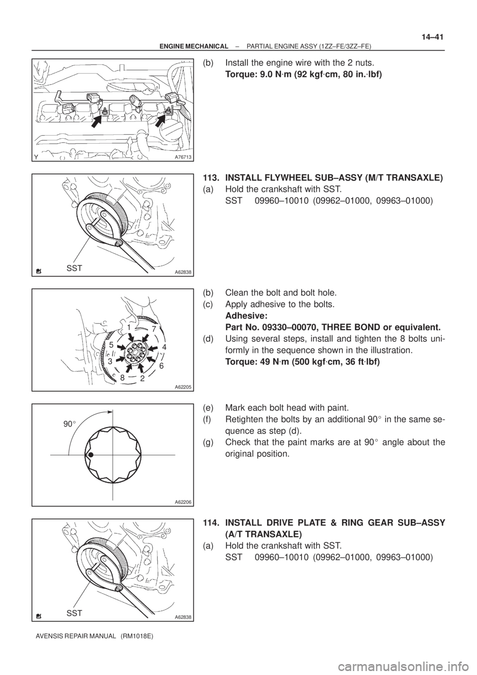
(b) Install the engine wire with the 2 nuts.
Torque: 9.0 N�m (92 kgf�cm, 80 in.�lbf)
113. INSTALL FLYWHEEL SUB±ASSY (M/T TRANSAXLE)
(a) Hold the crankshaft with SST.
SST 09960±10010 (09962±01000, 09963±01000)
(b) Clean the bolt and bolt hole.
(c) Apply adhesive to the bolts.
Adhesive:
Part No. 09330±00070, THREE BOND or equivalent.
(d) Using several steps, install and tighten the 8 bolts uni-
formly in the sequence shown in the illustration.
Torque: 49 N�m (500 kgf�cm, 36 ft�lbf)
(e) Mark each bolt head with paint.
(f) Retighten the bolts by an additional 90� in the same se-
quence as step (d).
(g) Check that the paint marks are at 90� angle about the
original position.
114. INSTALL DRIVE PLATE & RING GEAR SUB±ASSY
(A/T TRANSAXLE)
(a) Hold the crankshaft with SST.
SST 09960±10010 (09962±01000, 09963±01000)

AVENSIS REPAIR MANUAL (RM1018E)
(3) Turn the crankshaft counterclo")