Page 3461 of 5135
01±14
± INTRODUCTIONTERMS
1AZ±FSE ENGINE REPAIR MANUAL (RM1019E) TCM
Transmission Control ModuleTransmission ECU, ECT ECU
TPThrottle PositionThrottle Position
TRTransmission Range±
TVVThermal Vacuum ValveBimetallic Vacuum Switching Valve (BVSV)
Thermostatic Vacuum Switching Valve (TVSV)
TWCThree±Way Catalytic Converter
Three±Way Catalytic (TWC)
Manifold Converter
CC
RO
TWC+OCThree±Way + Oxidation Catalytic ConverterCCR + CCo
VA FVolume Air FlowAir Flow Meter
VRVoltage RegulatorVoltage Regulator
VSSVehicle Speed SensorVehicle Speed Sensor
WOTWide Open ThrottleFull Throttle
WU±OCWarm Up Oxidation Catalytic Converter±
WU±TWCWarm Up Three±Way Catalytic Converter±
3GRThird Gear±
4GRFourth Gear±
Page 3462 of 5135

TERMS
ABBREVIATIONS USED IN THIS MANUAL
AbbreviationsMeaning
ABSAnti±Lock Brake System
A/CAir Conditioner
ACAlternating")
010B9±09
± INTRODUCTIONTERMS
01±7
1AZ±FSE ENGINE REPAIR MANUAL (RM1019E)
TERMS
ABBREVIATIONS USED IN THIS MANUAL
AbbreviationsMeaning
ABSAnti±Lock Brake System
A/CAir Conditioner
ACAlternating Current
ACCAccessory
ACISAcoustic Control Induction System
ACSDAutomatic Cold Start Device
A.D.D.Automatic Disconnecting Differential
A/FAir±Fuel Ratio
AHCActive Height Control Suspension
ALRAutomatic Locking Retractor
ALTAlternator
AMPAmplifier
ANTAntenna
Approx.Approximately
ASSYAssembly
A/T, ATMAutomatic Transmission (Transaxle)
AT FAutomatic Transmission Fluid
AUTOAutomatic
AUXAuxiliary
AV GAverage
AV SAdaptive Variable Suspension
B+Battery Voltage
BABrake Assist
BACSBoost Altitude Compensation System
BATBattery
BDCBottom Dead Center
B/LBi±Level
B/SBore±Stroke Ratio
BTDCBefore Top Dead Center
BVSVBimetallic Vacuum Switching Valve
CBCircuit Breaker
CCoCatalytic Converter For Oxidation
CDCompact Disc
CFCornering Force
CGCenter Of Gravity
CHChannel
CKDComplete Knock Down
COMB.Combination
CPECoupe
CPSCombustion Pressure Sensor
CPUCentral Processing Unit
CRSChild Restraint System
CTRCenter
C/VCheck Valve
CVControl Valve
CWCurb Weight
DCDirect Current
DEFDefogger
Page 3463 of 5135
Abbreviations Meaning
DFLDeflector
DIFF.Differential
DIFF. LOCKDifferential Lock
D/INJDirect Injection
DLCData Link Connector
DLIDis")
01±8
± INTRODUCTIONTERMS
1AZ±FSE ENGINE REPAIR MANUAL (RM1019E)Abbreviations Meaning
DFLDeflector
DIFF.Differential
DIFF. LOCKDifferential Lock
D/INJDirect Injection
DLCData Link Connector
DLIDistributorless Ignition
DOHCDouble Overhead Camshaft
DPDash Pot
DSDead Soak
DSPDigital Signal Processor
DTCDiagnostic Trouble Code
DVDDigital Versatile Disc
EBDElectric Brake Force Distribution
ECAMEngine Control And Measurement System
ECDElectronic Controlled Diesel
ECDYEddy Current Dynamometer
ECTElectronic Control Transmission
ECUElectronic Control Unit
EDElectro±Deposited Coating
EDUElectronic Driving Unit
EDICElectric Diesel Injection Control
EFIElectronic Fuel Injection
E/GEngine
EGRExhaust Gas Recirculation
EGR±VMEGR±Vacuum Modulator
ELREmergency Locking Retractor
EMPSElectric Motor Power Steering
ENGEngine
ESAElectronic Spark Advance
ETCS±iElectronic Throttle Control System±intelligent
EVAPEvaporative Emission Control
EVPEvaporator
E±VRVElectric Vacuum Regulating Valve
EXExhaust
FEFuel Economy
FFFront±Engine Front±Wheel±Drive
F/GFuel Gauge
FIPGFormed In Place Gasket
FLFusible Link
F/PFuel Pump
FPUFuel Pressure Up
FrFront
F/WFlywheel
FW/DFlywheel Damper
FWDFront±Wheel±Drive
GASGasoline
GNDGround
GPSGlobal Positioning System
HACHigh Altitude Compensator
H/BHatchback
H±FUSEHigh Current Fuse
Page 3464 of 5135
Abbreviations Meaning
HIHigh
HIDHigh Intensity Discharge (Head Lamp)
HSGHousing
HTHard Top
HWSHeated Windshield System
ICIntegrated")
± INTRODUCTIONTERMS
01±9
1AZ±FSE ENGINE REPAIR MANUAL (RM1019E)Abbreviations Meaning
HIHigh
HIDHigh Intensity Discharge (Head Lamp)
HSGHousing
HTHard Top
HWSHeated Windshield System
ICIntegrated Circuit
IDIIndirect Diesel Injection
IFSIndependent Front Suspension
IGIgnition
IIAIntegrated Ignition Assembly
INIntake (Manifold, Valve)
INTIntermittent
I/PInstrument Panel
IRSIndependent Rear Suspension
ISCIdle Speed Control
J/BJunction Block
J/CJunction Connector
KDKick±Down
LANLocal Area Network
LBLiftback
LCDLiquid Crystal Display
LEDLight Emitting Diode
LHLeft±Hand
LHDLeft±Hand Drive
L/H/WLength, Height, Width
LLCLong±Life Coolant
LNGLiquified Natural Gas
LOLow
LPGLiquified Petroleum Gas
LSDLimited Slip Differential
LSP & PVLoad Sensing Proportioning And Bypass Valve
LSPVLoad Sensing Proportioning Valve
MAPManifold Absolute Pressure
MAX.Maximum
MICMicrophone
MILMalfunction Indicator Lamp
MIN.Minimum
MG1Motor Generator No.1
MG2Motor Generator No.2
MPMultipurpose
MPIMultipoint Electronic Injection
MPXMultiplex Communication System
M/T, MTMManual Transmission (Transaxle)
MTMount
MTGMounting
NNeutral
NANatural Aspiration
No.Number
O2SOxygen Sensor
O/DOverdrive
OEMOriginal Equipment Manufacturing
Page 3466 of 5135
± INTRODUCTIONTERMS
01±11
1AZ±FSE ENGINE REPAIR MANUAL (RM1019E)Abbreviations Meaning
TISTotal Information System For Vehicle Development
T/MTransmission
TMCTOYOTA Motor Corporation
TMMKTOYOTA Motor Manufacturing Kentucky, Inc.
TRCTraction Control System
TURBOTurbocharge
TWCThree±Way Catalyst
U/DUnderdrive
U/SUndersize
VCVVacuum Control Valve
VENTVentilator
VINVehicle Identification Number
VPSVariable Power Steering
VSCVehicle Stability Control
VSVVacuum Switching Valve
VTVVacuum Transmitting Valve
VVT±iVariable Valve Timing±intelligent
w/With
WGNWagon
W/HWire Harness
w/oWithout
WU±TWCWarm Up Three±way Catalytic Converter
WU±OCWarm Up Oxidation Catalytic Converter
1stFirst
2ndSecond
2WDTwo Wheel Drive Vehicle (4 x 2)
3rdThird
4thFourth
4WDFour Wheel Drive Vehicle (4 x 4)
4WSFour Wheel Steering System
5thFifth
Page 3513 of 5135
 ISC
Idle Speed Control±
KSKnock SensorKnock Sensor
MAFMass Air FlowAir Flow Meter
MAPManifold Absolute")
± INTRODUCTIONTERMS FOR MANUAL TRANSAXLE REPAIR MANUAL
01±7
C250 M/T REPAIR MANUAL (RM1020E) ISC
Idle Speed Control±
KSKnock SensorKnock Sensor
MAFMass Air FlowAir Flow Meter
MAPManifold Absolute PressureManifold Pressure
Intake Vacuum
MCMixture Control
Electric Bleed Air Control Valve (EBCV)
Mixture Control Valve (MCV)
Electric Air Control Valve (EACV)
MDPManifold Differential Pressure±
MFIMultiport Fuel InjectionElectronic Fuel Injection (EFI)
MILMalfunction Indicator LampCheck Engine Light
MSTManifold Surface temperature±
MVZManifold Vacuum Zone±
NVRAMNon±Volatile Random Access Memory±
O2SOxygen SensorOxygen Sensor, O2 Sensor (O2S)
OBDOn±Board DiagnosticOn±Board Diagnostic (OBD)
OCOxidation Catalytic ConverterOxidation Catalyst Converter (OC), CC0
OPOpen LoopOpen Loop
PAIRPulsed Secondary Air InjectionAir Suction (AS)
PCMPowertrain Control Module±
PNPPark/Neutral Position±
PROMProgrammable Read Only Memory±
PSPPower Steering Pressure±
PTOXPeriodic Trap OxidizerDiesel Particulate Filter (DPF)
Diesel Particulate Trap (DPT)
RAMRandom Access MemoryRandom Access Memory (RAM)
RMRelay Module±
ROMRead Only MemoryRead Only Memory (ROM)
RPMEngine SpeedEngine Speed
SCSuperchargerSupercharger
SCBSupercharger Bypass±
SFISequential Multiport Fuel InjectionElectronic Fuel Injection (EFI), Sequential Injection
SPLSmoke Puff Limiter±
SRIService Reminder Indicator±
SRTSystem Readiness Test±
STScan Tool±
TBThrottle BodyThrottle Body
TBIThrottle Body Fuel InjectionSingle Point Injection
Central Fuel Injection (Ci)
TCTurbochargerTurbocharger
TCCTorque Converter ClutchTorque Converter
TCMTransmission Control ModuleTransmission ECU (Electronic Control Unit)
TPThrottle PositionThrottle Position
TRTransmission Range±
TVVThermal Vacuum ValveBimetallic Vacuum Switching Valve (BVSV)
Thermostatic Vacuum Switching Valve (TVSV)
TWCThree±Way Catalytic ConverterThree±Way Catalytic (TWC)
CC
RO
TWC+OCThree±Way + Oxidation Catalytic ConverterCCR + CCO
VA FVolume Air FlowAir Flow Meter
VRVoltage RegulatorVoltage Regulator
VSSVehicle Speed SensorVehicle Speed Sensor (Read Switch Type)
WOTWide Open ThrottleFull Throttle
Page 3515 of 5135

C250 M/T REPAIR MANUAL (RM1020E)
OVERHAUL
1. INSPECT 1ST GEAR THRUST CLEARANCE
(a) Using a feele")
410DH±01
C80538
C68312
C68309
C68254
41±48
± MANUAL TRANSMISSION/TRANSAXLEOUTPUT SHAFT ASSY (C250)
C250 M/T REPAIR MANUAL (RM1020E)
OVERHAUL
1. INSPECT 1ST GEAR THRUST CLEARANCE
(a) Using a feeler gauge, measure the 1st gear thrust clear-
ance.
Standard clearance:
0.10 ± 0.40 mm (0.0039 ± 0.0157 in.)
Maximum clearance:
0.40 mm (0.0157 in.)
2. INSPECT 2ND GEAR THRUST CLEARANCE
(a) Using a dial indicator, measure the 2nd gear thrust clear-
ance.
Standard clearance:
0.1 ± 0.45 mm (0.0039 ± 0.0177 in.)
Maximum clearance:
0.45 mm (0.0177 in.)
3. INSPECT 1ST GEAR RADIAL CLEARANCE
(a) Using a dial indicator, measure the 1st gear radial clear-
ance between the gear and shaft.
Standard clearance:
0.015 ± 0.058 mm (0.0006 ± 0.0023 in.)
Maximum clearance:
0.058 mm (0.0023 in.)
If the clearance exceeds the maximum, replace the 1st gear
needle roller bearing.
4. INSPECT 2ND GEAR RADIAL CLEARANCE
(a) Using a dial indicator, measure the 2nd gear radial clear-
ance between the gear and shaft.
Standard clearance:
0.015 ± 0.058 mm (0.0006 ± 0.0023 in.)
Maximum clearance:
0.058 mm (0.0023 in.)
If the clearance exceeds the maximum, replace the 2nd gear
needle roller bearing.
Page 3516 of 5135
C80539
SST
C68005
���
C80431
C80541
D30552
± MANUAL TRANSMISSION/TRANSAXLEOUTPUT SHAFT ASSY (C250)
41±49
C250 M/T REPAIR MANUAL (RM1020E)
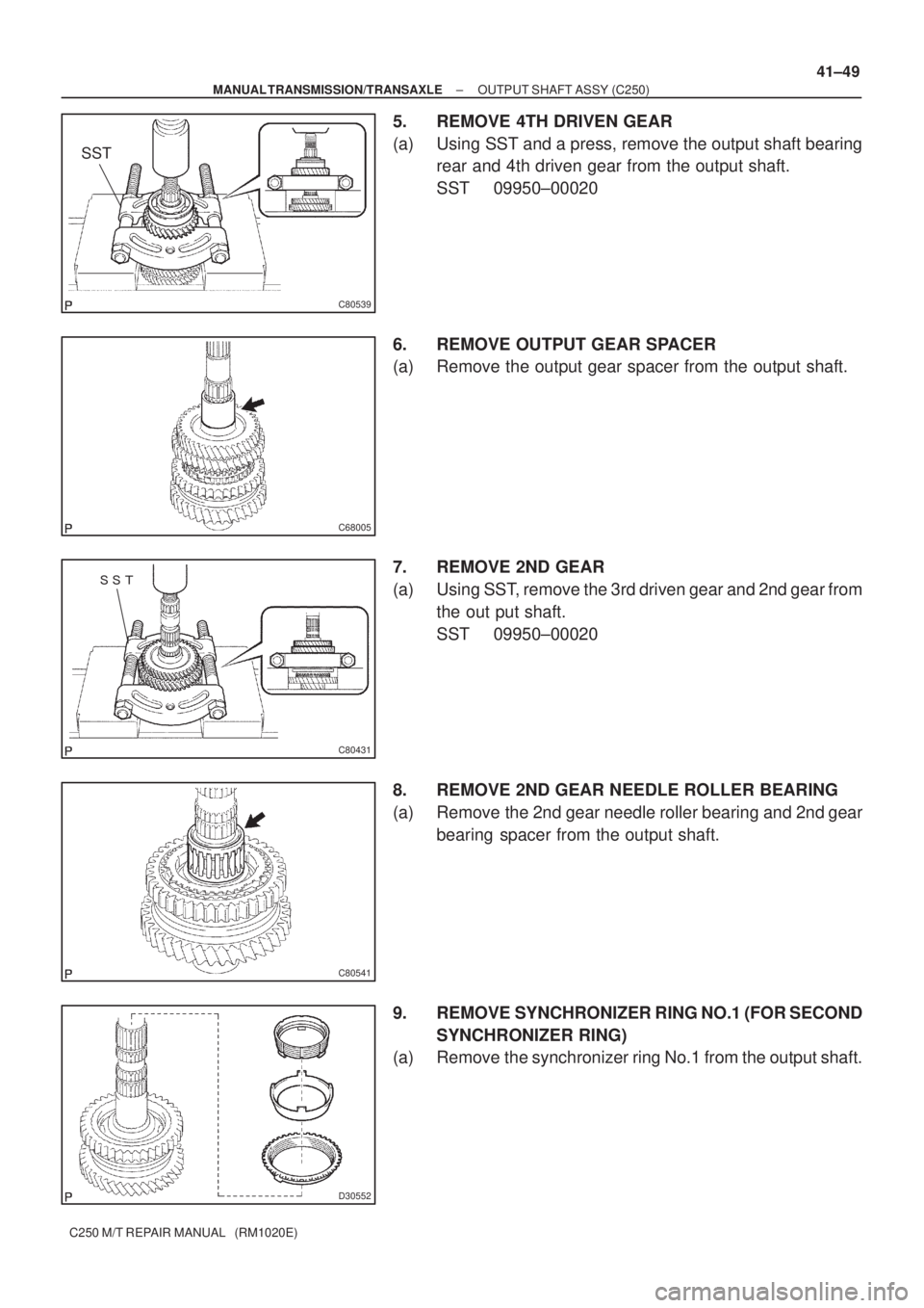
5. REMOVE 4TH DRIVEN GEAR
(a) Using SST and a press, remove the output shaft bearing
rear and 4th driven gear from the output shaft.
SST 09950±00020
6. REMOVE OUTPUT GEAR SPACER
(a) Remove the output gear spacer from the output shaft.
7. REMOVE 2ND GEAR
(a) Using SST, remove the 3rd driven gear and 2nd gear from
the out put shaft.
SST 09950±00020
8. REMOVE 2ND GEAR NEEDLE ROLLER BEARING
(a) Remove the 2nd gear needle roller bearing and 2nd gear
bearing spacer from the output shaft.
9. REMOVE SYNCHRONIZER RING NO.1 (FOR SECOND
SYNCHRONIZER RING)
(a) Remove the synchronizer ring No.1 from the output shaft.
 TCM
Transmission Control ModuleTransmission ECU, ECT ECU
TPThrottle PositionThrottle Position
TRTransmission Range±
TVVThermal Va")
Abbreviations Meaning
TISTotal Information System For Vehicle Development
T/MTransmission
TMCTOYOTA Motor Corporation
TMMKTOYOTA Mo")