Page 2794 of 5135
D30061
A
B C
A
D30481
������D30691
AA
B
D30482
A
B 41±20
± MANUAL TRANSMISSION/TRANSAXLEMANUAL TRANSAXLE ASSY (1ZZ±FE/3ZZ±FE)
AVENSIS REPAIR MANUAL (RM1018E)
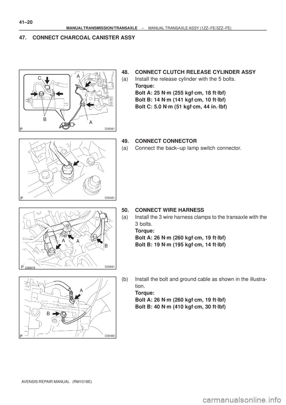
47. CONNECT CHARCOAL CANISTER ASSY
48. CONNECT CLUTCH RELEASE CYLINDER ASSY
(a) Install the release cylinder with the 5 bolts.
Torque:
Bolt A: 25 N�m (255 kgf�cm, 18 ft�lbf)
Bolt B: 14 N�m (141 kgf�cm, 10 ft�lbf)
Bolt C: 5.0 N�m (51 kgf�cm, 44 in.�lbf)
49. CONNECT CONNECTOR
(a) Connect the back±up lamp switch connector.
50. CONNECT WIRE HARNESS
(a) Install the 3 wire harness clamps to the transaxle with the
3 bolts.
Torque:
Bolt A: 26 N�m (260 kgf�cm, 19 ft�lbf)
Bolt B: 19 N�m (195 kgf�cm, 14 ft�lbf)
(b) Install the bolt and ground cable as shown in the illustra-
tion.
Torque:
Bolt A: 26 N�m (260 kgf�cm, 19 ft�lbf)
Bolt B: 40 N�m (410 kgf�cm, 30 ft�lbf)
Page 2795 of 5135

41±21
AVENSIS REPAIR MANUAL (RM1018E)
51. INSTALL BATTERY CARRIER
(a) Install the battery carrier and 4 bolts.
Torque")
D30480
±
MANUAL TRANSMISSION/TRANSAXLE MANUAL TRANSAXLE ASSY (1ZZ±FE/3ZZ±FE)
41±21
AVENSIS REPAIR MANUAL (RM1018E)
51. INSTALL BATTERY CARRIER
(a) Install the battery carrier and 4 bolts.
Torque: 13 N �m (131 kgf �cm, 9 ft �lbf)
52. INSTALL BATTERY TRAY
53. INSTALL BATTERY
54. INSTALL BATTERY CLAMP SUB±ASSY Torque:
Bolt: 5.0 N �m (51 kgf �cm, 44 in. �lbf)
Nut: 3.5 N �m (36 kgf �cm, 31 in. �lbf)
55. INSTALL AIR CLEANER ASSY Torque: 5.0 N �m (51 kgf �cm, 44 in. �lbf)
56. INSTALL CYLINDER HEAD COVER NO.2 Torque: 7.0 N �m (71 kgf �cm, 62 in. �lbf)
57. INSTALL ENGINE ROOM COVER SIDE
58. INSTALL RADIATOR SUPPORT OPENING COVER
59. INSTALL HOOD SUB±ASSY Torque: 13 N �m (133 kgf �cm, 10 ft �lbf)
60.INSPECT HOOD SUB±ASSY (See page 75±2)
61.ADJUST HOOD SUB±ASSY (See page 75±2)
62.ADD TRANSAXLE OIL (See page 41±3)
63.INSPECT TRANSAXLE OIL (See page 41±2)
64. INSTALL FRONT WHEELS
Torque: 103 N �m (1,050 kgf �cm, 76 ft �lbf)
65.INSTALL STEERING INTERMEDIATE SHAFT (See page 50±9)
66.INSTALL STEERING COLUMN HOLE COVER SUB±ASSY NO.1 (See page 50±9)
67.INSTALL STEERING INTERMEDIATE SHAFT ASSY NO.2 (See page 50±9)
68.INSTALL COLUMN HOLE COVER SILENCER SHEET (See page 50±9)
69. PLACE FRONT WHEELS FACING STRAIGHT AHEAD
70. STEERING WHEEL CENTER POINT
71.INSPECT AND ADJUST FRONT WHEEL ALIGNMENT (See page 26±6)
72. INSTALL ENGINE UNDER COVER LH
73. INSTALL ENGINE UNDER COVER RH
74. CHECK ABS SPEED SENSOR SIGNAL
(a)w/ VSC (See page 05±756)
(b)w/o VSC (See page 05±699)
75.HEADLIGHT AIM ONLY (W/ DISCHARGE HEAD LAMP) (See page 65±19)
Page 2796 of 5135

410DS±01
D30478
Battery Clamp Sub±assy
Battery Tray
Charcoal Canister Assy Battery Carrier
Transmission Control Cable AssyClipAir Cleaner Assy
Hood Sub±assy
Cylinder Head Cover No.2
Starter AssyBack±up Lamp
SwitchConnector
Transverse Engine
Engine Mounting Bracket
Clip
Clip
ClipClip
37 (380, 27)
Starter Connector
Transverse Engine
Engine Mounting Insulator
52 (530, 38)
52 (530, 38)
Ground Cable � Gasket
7.0 (71, 62 in.�lbf)
Filler Plug
37 (380, 27)
23 (230, 17)
47 (479, 35)
N´m (kgf´cm, ft´lbf) : Specified torque
19 (195, 14)
13 (130, 9)
64 (653, 47)
64 (653, 47)
5.0 (51, 44 in.�lbf)
� Non±reusable part
5.0 (51, 44 in.�lbf)
14 (141, 10)
13 (133, 10)
13 (131, 9)
5.0 (51, 44 in.�lbf)
26 (260, 19)
25 (255, 18)
80 (816, 59)
26 (260, 19)
23 (230, 17)
Engine Room Cover Side
Radiator Support Opening Cover
40 (410, 30)
39 (400, 29)
Manual Transaxle Assy
64 (653, 47)
Battery
Clutch Release Cylinder Assy
± MANUAL TRANSMISSION/TRANSAXLEMANUAL TRANSAXLE ASSY (1ZZ±FE/3ZZ±FE)
41±13
AVENSIS REPAIR MANUAL (RM1018E)
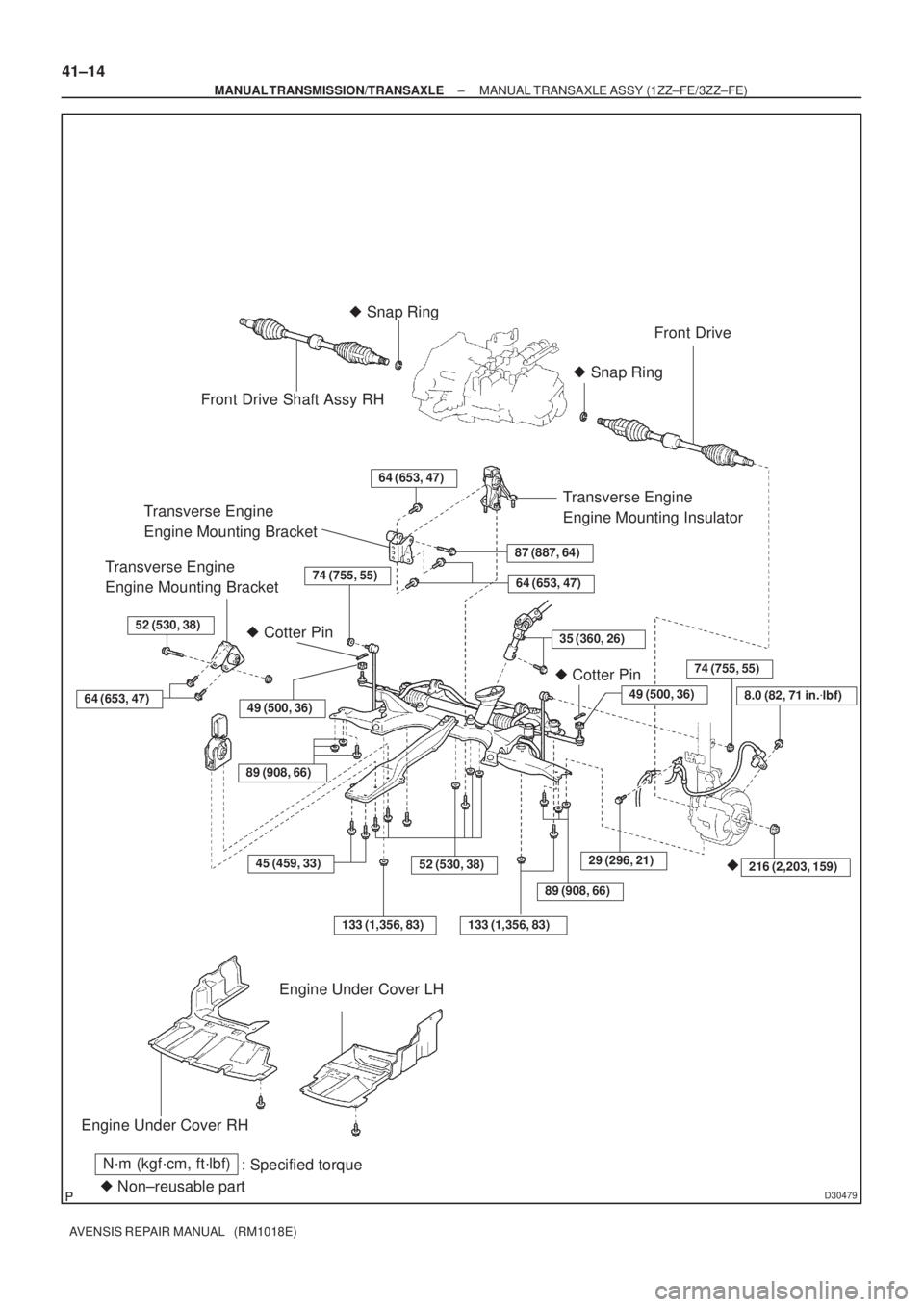
MANUAL TRANSAXLE ASSY (1ZZ±FE/3ZZ±FE)
COMPONENTS
Page 2797 of 5135
D30479
Front Drive Shaft Assy RH� Snap Ring
Front Drive
� Snap Ring
Transverse Engine
Engine Mounting BracketTransverse Engine
Engine Mounting Insulator
64 (653, 47)
87 (887, 64)Transverse Engine
Engine Mounting Bracket
� Cotter Pin
64 (653, 47)
52 (530, 38)
� Cotter Pin
Engine Under Cover RH
� Non±reusable part
N´m (kgf´cm, ft´lbf)
: Specified torque
64 (653, 47)
�216 (2,203, 159)45 (459, 33)
Engine Under Cover LH
35 (360, 26)
74 (755, 55)
52 (530, 38)
49 (500, 36)
133 (1,356, 83)
29 (296, 21)
49 (500, 36)
74 (755, 55)
89 (908, 66)
8.0 (82, 71 in.�lbf)
133 (1,356, 83)
89 (908, 66)
41±14
± MANUAL TRANSMISSION/TRANSAXLEMANUAL TRANSAXLE ASSY (1ZZ±FE/3ZZ±FE)
AVENSIS REPAIR MANUAL (RM1018E)
Page 2844 of 5135

�����\b�����D30389
AZ Series:1CD±FTV:
No.1 Engine Hanger
No.2 Engine Hanger
No.1 Engine Hanger
No.2 Engine Hanger
No.1 Engine
Hanger UPR
D29969
C94595
51±38
±
POWER STEERING RACK & PINION POWER STEERING GEAR ASSY
AVENSIS REPAIR MANUAL (RM1018E)
15.SEPARATE FRONT SUSPENSION ARM SUB±ASSY LOWER NO.1 LH (See page 30±6)
16. SEPARATE FRONT SUSPENSION ARM SUB±ASSY LOWER NO.1 RH
HINT:
Perform the same procedure on the other side.
17. REMOVE HOOD SUB±ASSY
18. REMOVE CYLINDER HEAD COVER SUB±ASSY 19. SUSPEND ENGINE ASSEMBLY
(a) Install the 2 or 3 engine hangers with the bolts in the cor-rect direction.
Parts No. :
AZ Series:1CD±FTV:
No.1 Engine Hanger12281±2801012281±27050
No.1 Engine Hanger UPR±Yellow: 12284±27020
Black: 12284±27030
No.2 Engine Hanger12282±28010Yellow: 12282±27060Black: 12282±27070
Bolt91512±6102091642±81025
Torque:
AZ Series:
38 N �m (390 kgf �cm, 28 ft �lbf)
1CD±FTV:
37 N �m (375 kgf �cm, 27 ft �lbf)
(b) Attach the engine chain hoist to the engine hangers.
CAUTION:
Do not attempt to hang the engine by hooking the chain to
any other parts.
20. REMOVE FRONT SUSPENSION CROSSMEMBER
SUB±ASSY
(a) Remove the 4 bolts and separate the center member.
(b) Remove the bolt and the 3 nuts, separate the engine mounting insulator RR from the crossmember sub±assy.
(c) Using a transmission jack, support the crossmember
sub±assy.
Page 2849 of 5135

43. INSTALL FRONT SUSPENSION CROSSMEMB")
C94598
C94596
A
BB
B
LH:
C94597
A
BB
B
RH:
C94595
D29969
A
B
A
B
± POWER STEERINGRACK & PINION POWER STEERING GEAR ASSY
51±43
AVENSIS REPAIR MANUAL (RM1018E)
43. INSTALL FRONT SUSPENSION CROSSMEMBER
SUB±ASSY
(a) Using a transmission jack, support the crossmember
sub±assy w/power steering gear assy.
(b) Install the 2 stopper front onto the crossmember sub±
assy.
(c) Install the crossmember sub±assy with the 2 nuts.
Torque: 133 N�m (1,356 kgf�cm, 98 ft�lbf)
(d) Install the stopper rear onto the crossmember bracket LH.
(e) Install the crossmember bracket LH with the 4 bolts.
Torque:
Bolt A: 133 N�m (1,356 kgf�cm, 98 ft�lbf)
Bolt B: 80 N�m (816 kgf�cm, 59 ft�lbf)
(f) Install the stopper rear onto the crossmember bracket
RH.
(g) Install the crossmember bracket RH with the 4 bolts.
Torque:
Bolt A: 133 N�m (1,356 kgf�cm, 98 ft�lbf)
Bolt B: 80 N�m (816 kgf�cm, 59 ft�lbf)
(h) Install the engine mounting insulator RR to the cross-
member sub±assy with the bolt and the 3 nuts.
Torque: 52 N�m (530 kgf�cm, 38 ft�lbf)
(i) Install the center member with the 4 bolts.
Torque:
Bolt A: 45 N�m (459 kgf�cm, 33 ft�lbf)
Bolt B: 52 N�m (530 kgf�cm, 38 ft�lbf)
Page 3314 of 5135

INSPECTION
1.INSPECT TRANSMITTER SUB±ASSY MODULE SET DOOR CONTROL")
730EZ±03
I34799
±
THEFT DETERRENT & DOOR LOCK TRANSMITTER SUB±ASSY MODULE SET DOOR
CONTROL73±19
AVENSIS REPAIR MANUAL (RM1018E)
INSPECTION
1.INSPECT TRANSMITTER SUB±ASSY MODULE SET DOOR CONTROL
(a)Inspect operation of the transmitter.
(1)Remove the battery (lithium battery) from the transmitter (See page 73±17).
(2)Install a new or normal battery (lithium battery).
HINT:
When a new or normal battery is not available, connect 2 new
1.5 V batteries in a series, connect the battery positive (+) to the
battery receptacle side terminal and battery negative (±) to the
bottom terminal, then apply 3 V of voltage to the transmitter.
(3)In a location that is approx. 1 m (3.28 ft) away from the driver side ou\
tside door handle in the right direction, point the key plate of the transmitter at the vehicle and che\
ck operation of the transmit-
ter by pressing the transmission switch on the transmitter body.
Standard:
The door lock can be operated via the remote control.
The LED lights up more than once.
HINT:
�The minimum operational distance differs, depending on the operator, the way the transmitter is held,
and the location.
�Since the transmitter uses faint electric waves, the operational distanc\
e might be shortened if noise
or strong electric wave occurs in the area where the frequency is used.
(4)Install the battery (lithium battery).
(b)Inspect the battery capacity.
HINT:
�The capacity of the battery can be determined only when the battery is inst\
alled in the transmitter. For
a lithium battery used in the transmitter, a voltage of more than 2.5 V is shown on the tester until the
energy is completely consumed, while no battery is installed in the transmitte\
r. Therefore, it is neces-
sary to measure the voltage while the battery is installed in the transmitte\
r (a resistance of 1.2 k �is
applied to the battery) when checking the amount of energy left in the \
battery.
�If the transmitter is faulty, the amount of energy left in the battery might not be checked correctl\
y.
(1)Remove the battery (lithium battery) from the transmitter (See page 73±17).
Page 3315 of 5135

(2) Connect the lead to the negative (±) terminal of the
transm")
I34797
Lead
I34798
73±20± THEFT DETERRENT & DOOR LOCKTRANSMITTER SUB±ASSY MODULE SET DOOR
CONTROL
AVENSIS REPAIR MANUAL (RM1018E)
(2) Connect the lead to the negative (±) terminal of the
transmitter and install the battery.
(3) Connect the tester positive (+) probe to the (+) bat-
tery (lithium battery) and the tester negative (±)
probe to the lead respectively.
(4) Press one of the transmission switches on the
transmitter for approx. 1 second.
(5) Press the transmission switch on the transmitter
again to check the voltage.
Standard: 2.2 V or higher
HINT:
�When the temperature of the battery is low, the inspection can not be made correctly.
When the outcome of the test is less than 2.2 V, conduct the test again after leaving the battery in a
place with a temperature of 18�C (64�F) for more than 30 minutes.
�The automatic power±off function causes the voltage of the battery to be 2.5 V or more (a voltage with
no resistance applied to the battery) when 0.8 seconds have passed after the switch is pressed. There-
fore, make sure to read the voltage just after the switch is pressed.
�Because high voltage might be shown once or twice after the battery returns to the specified tempera-
ture, the inspection should be made with the voltage shown after the switch is pressed at least 3 times.
(6) Disconnect the lead.
(7) Set the battery (lithium battery) in the transmitter.