Page 3399 of 5135

750N9±01
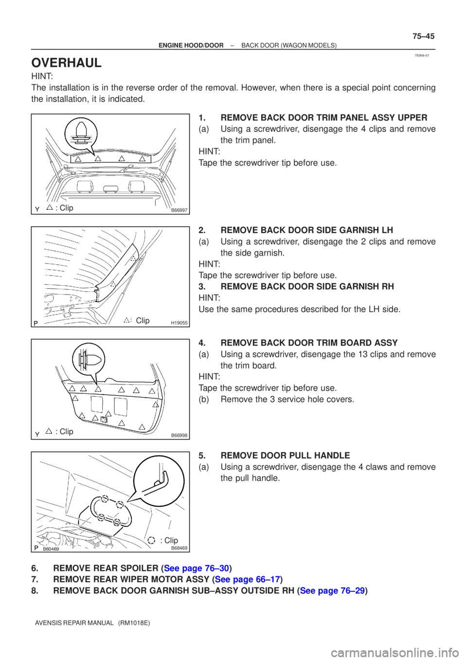
B66997: Clip
H19055Clip
B66998: Clip
������B68469: Clip
±
ENGINE HOOD/DOOR BACK DOOR(WAGON MODELS)
75±45
AVENSIS REPAIR MANUAL (RM1018E)
OVERHAUL
HINT:
The installation is in the reverse order of the removal. However, when there is a special point concerning
the installation, it is indicated.
1.REMOVE BACK DOOR TRIM PANEL ASSY UPPER
(a)Using a screwdriver, disengage the 4 clips and removethe trim panel.
HINT:
Tape the screwdriver tip before use.
2.REMOVE BACK DOOR SIDE GARNISH LH
(a)Using a screwdriver, disengage the 2 clips and remove the side garnish.
HINT:
Tape the screwdriver tip before use.
3.REMOVE BACK DOOR SIDE GARNISH RH
HINT:
Use the same procedures described for the LH side.
4.REMOVE BACK DOOR TRIM BOARD ASSY
(a)Using a screwdriver, disengage the 13 clips and remove the trim board.
HINT:
Tape the screwdriver tip before use.
(b)Remove the 3 service hole covers.
5.REMOVE DOOR PULL HANDLE
(a)Using a screwdriver, disengage the 4 claws and remove the pull handle.
6.REMOVE REAR SPOILER (See page 76±30)
7.REMOVE REAR WIPER MOTOR ASSY (See page 66±17)
8.REMOVE BACK DOOR GARNISH SUB±ASSY OUTSIDE RH (See page 76±29)
Page 3403 of 5135
750N7±01
B66987
Back Door Trim Panel Assy Upper
Back Door Side Garnish LH Wiper Motor AssyRear Spoiler
Back Door Garnish Sub±assy Outside RH
Back Door Trim Board Assy
Door Pull Handle
Back Door Lock Striker Back Door Side Garnish RH
Door Pull Handle
: Specified torque
N´m (kgf´cm, ft´lbf)
Floor Finish Plate Rear Wiper Arm and Blade Assy
Wiper Arm Head Cap
5.5 (56, 49 in.´lbf)
Rear Wiper w/ Packing
Washer
Back Door
Stay Assy LH
7.0 (71, 62 in.´lbf)
22 (264, 19)
11.5 (120, 8)
Back Door Stay Assy RH
7.0 (71, 62 in.´lbf)
8.0 (82, 71 in.´lbf)
19.5 (200, 14)
Back Door Service Hole Cover
Back Door Lock Assy
4.9 (49, 43 in.´lbf)4.9 (49, 43 in.´lbf)
75±42
± ENGINE HOOD/DOORBACK DOOR (WAGON MODELS)
AVENSIS REPAIR MANUAL (RM1018E)
BACK DOOR (WAGON MODELS)
COMPONENTS
Page 3404 of 5135

750N6±01
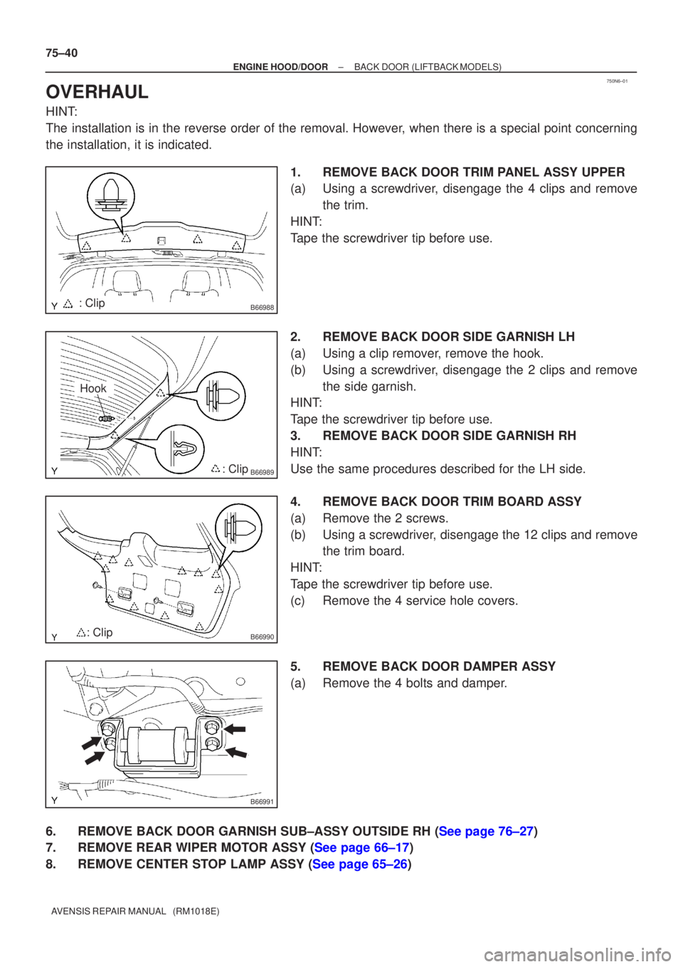
B66988: Clip
B66989: Clip
Hook
B66990: Clip
B66991
75±40
±
ENGINE HOOD/DOOR BACK DOOR(LIFTBACK MODELS)
AVENSIS REPAIR MANUAL (RM1018E)
OVERHAUL
HINT:
The installation is in the reverse order of the removal. However, when there is a special point concerning
the installation, it is indicated. 1.REMOVE BACK DOOR TRIM PANEL ASSY UPPER
(a)Using a screwdriver, disengage the 4 clips and removethe trim.
HINT:
Tape the screwdriver tip before use.
2.REMOVE BACK DOOR SIDE GARNISH LH
(a)Using a clip remover, remove the hook.
(b)Using a screwdriver, disengage the 2 clips and remove the side garnish.
HINT:
Tape the screwdriver tip before use.
3.REMOVE BACK DOOR SIDE GARNISH RH
HINT:
Use the same procedures described for the LH side.
4.REMOVE BACK DOOR TRIM BOARD ASSY
(a)Remove the 2 screws.
(b)Using a screwdriver, disengage the 12 clips and remove the trim board.
HINT:
Tape the screwdriver tip before use.
(c)Remove the 4 service hole covers.
5.REMOVE BACK DOOR DAMPER ASSY
(a)Remove the 4 bolts and damper.
6.REMOVE BACK DOOR GARNISH SUB±ASSY OUTSIDE RH (See page 76±27)
7.REMOVE REAR WIPER MOTOR ASSY (See page 66±17)
8.REMOVE CENTER STOP LAMP ASSY (See page 65±26)
Page 3408 of 5135
750N4±01
B66986
Back Door Trim
Panel Assy Upper
Back Door Trim Board Assy Back Door Side
Garnish LHBack Door Garnish Sub±assy
Outside RH
Floor Finish Plate Center Stop Lamp Assy
Back Door Lock Striker Hook
Back Door Side
Garnish RHBack Door Stay Assy RH
Back Door Lock Assy Rear Wiper Motor Assy
Back Door
Stay Assy LH
Back Door Service
Hole Cover
: Specified torqueN´m (kgf´cm, ft´lbf)
19.5 (200, 14)
5.5 (56, 49 in.´lbf)
Hook Rear Wiper Arm and Blade Assy
Rear Wiper
w/ Packing Washer
Wiper Arm Head Cap
Nut5.5 (56, 49 in.´lbf)
5.5 (56, 49 in.´lbf)
Cushion Rubber
Cushion Rubber
Rope Hook Assy
11.5 (120, 8)
22 (264, 19)
7.0 (71, 62 in.´lbf)
5.5 (56, 49 in.´lbf)
8.0 (82, 71 in.´lbf)
7.0 (71, 62 in.´lbf)22 (264, 19)
Female
Stopper RH
Female
Stopper LH
4.9 (49, 43 in.´lbf)Back Door Damper Assy
5.5 (56, 49 in.´lbf)
± ENGINE HOOD/DOORBACK DOOR (LIFTBACK MODELS)
75±37
AVENSIS REPAIR MANUAL (RM1018E)
BACK DOOR (LIFTBACK MODELS)
COMPONENTS
Page 3463 of 5135

01±8
± INTRODUCTIONTERMS
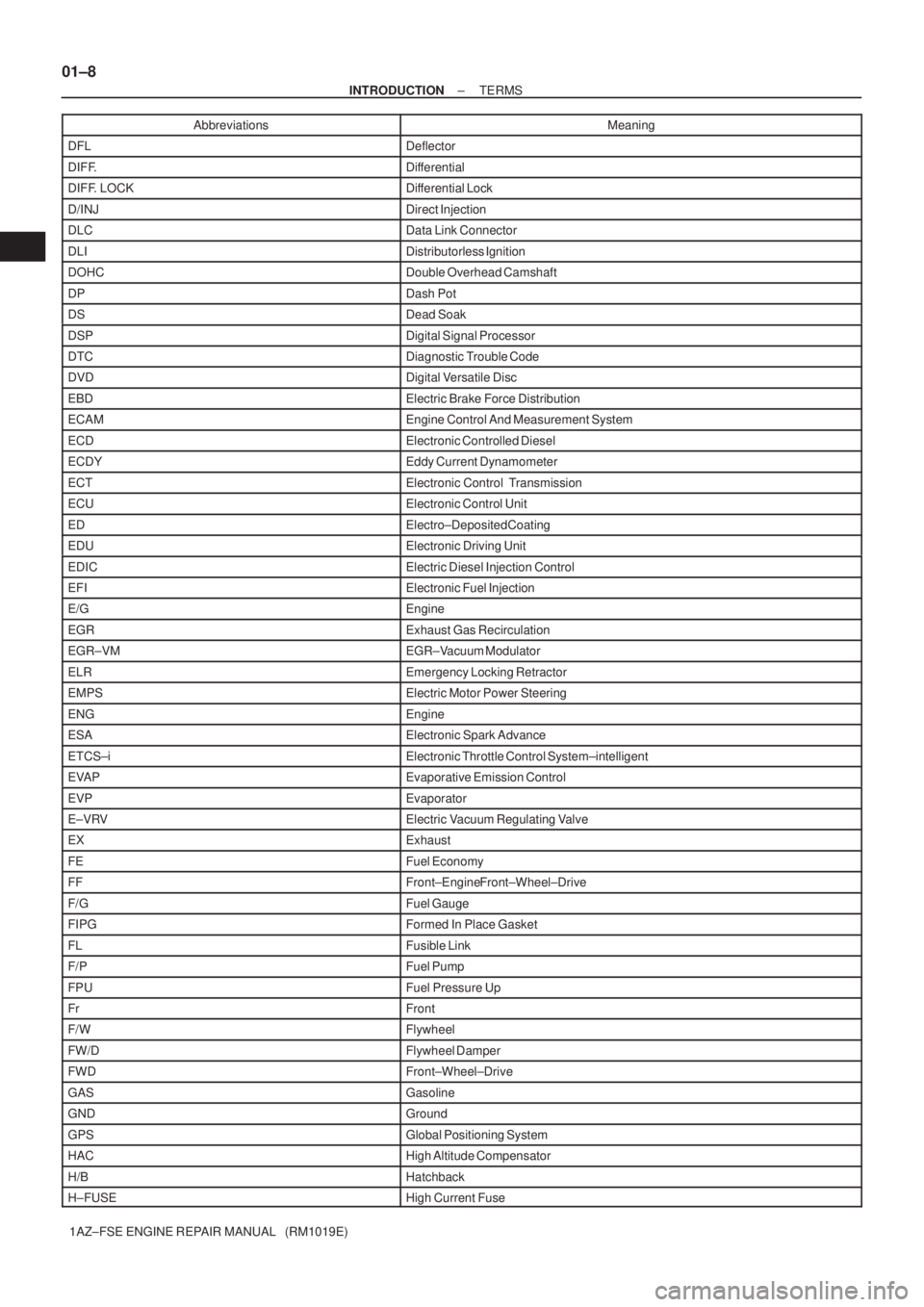
1AZ±FSE ENGINE REPAIR MANUAL (RM1019E)Abbreviations Meaning
DFLDeflector
DIFF.Differential
DIFF. LOCKDifferential Lock
D/INJDirect Injection
DLCData Link Connector
DLIDistributorless Ignition
DOHCDouble Overhead Camshaft
DPDash Pot
DSDead Soak
DSPDigital Signal Processor
DTCDiagnostic Trouble Code
DVDDigital Versatile Disc
EBDElectric Brake Force Distribution
ECAMEngine Control And Measurement System
ECDElectronic Controlled Diesel
ECDYEddy Current Dynamometer
ECTElectronic Control Transmission
ECUElectronic Control Unit
EDElectro±Deposited Coating
EDUElectronic Driving Unit
EDICElectric Diesel Injection Control
EFIElectronic Fuel Injection
E/GEngine
EGRExhaust Gas Recirculation
EGR±VMEGR±Vacuum Modulator
ELREmergency Locking Retractor
EMPSElectric Motor Power Steering
ENGEngine
ESAElectronic Spark Advance
ETCS±iElectronic Throttle Control System±intelligent
EVAPEvaporative Emission Control
EVPEvaporator
E±VRVElectric Vacuum Regulating Valve
EXExhaust
FEFuel Economy
FFFront±Engine Front±Wheel±Drive
F/GFuel Gauge
FIPGFormed In Place Gasket
FLFusible Link
F/PFuel Pump
FPUFuel Pressure Up
FrFront
F/WFlywheel
FW/DFlywheel Damper
FWDFront±Wheel±Drive
GASGasoline
GNDGround
GPSGlobal Positioning System
HACHigh Altitude Compensator
H/BHatchback
H±FUSEHigh Current Fuse
Page 3464 of 5135

± INTRODUCTIONTERMS
01±9
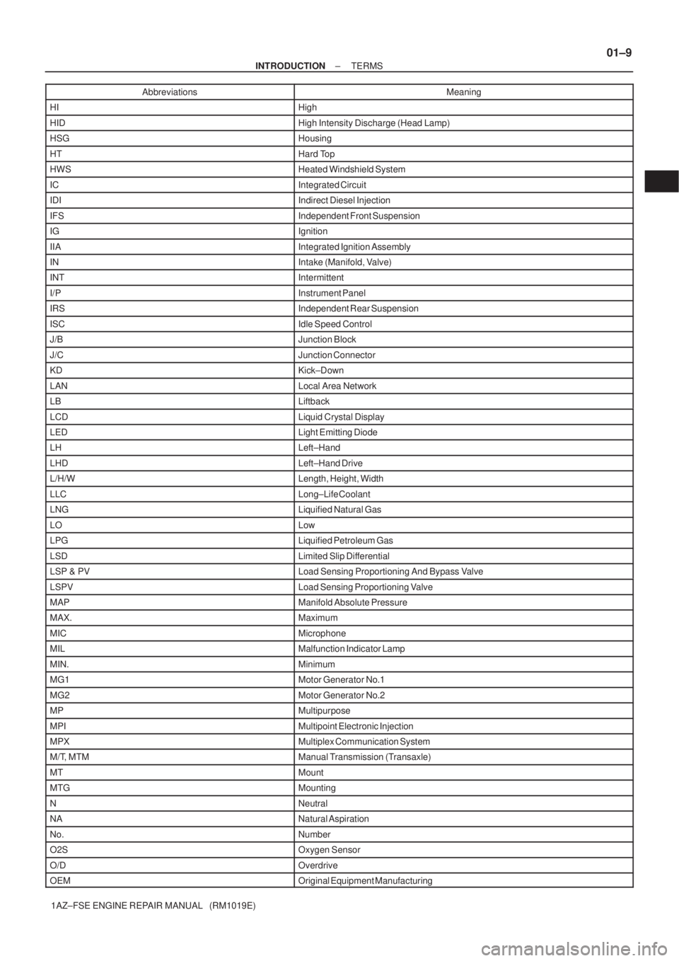
1AZ±FSE ENGINE REPAIR MANUAL (RM1019E)Abbreviations Meaning
HIHigh
HIDHigh Intensity Discharge (Head Lamp)
HSGHousing
HTHard Top
HWSHeated Windshield System
ICIntegrated Circuit
IDIIndirect Diesel Injection
IFSIndependent Front Suspension
IGIgnition
IIAIntegrated Ignition Assembly
INIntake (Manifold, Valve)
INTIntermittent
I/PInstrument Panel
IRSIndependent Rear Suspension
ISCIdle Speed Control
J/BJunction Block
J/CJunction Connector
KDKick±Down
LANLocal Area Network
LBLiftback
LCDLiquid Crystal Display
LEDLight Emitting Diode
LHLeft±Hand
LHDLeft±Hand Drive
L/H/WLength, Height, Width
LLCLong±Life Coolant
LNGLiquified Natural Gas
LOLow
LPGLiquified Petroleum Gas
LSDLimited Slip Differential
LSP & PVLoad Sensing Proportioning And Bypass Valve
LSPVLoad Sensing Proportioning Valve
MAPManifold Absolute Pressure
MAX.Maximum
MICMicrophone
MILMalfunction Indicator Lamp
MIN.Minimum
MG1Motor Generator No.1
MG2Motor Generator No.2
MPMultipurpose
MPIMultipoint Electronic Injection
MPXMultiplex Communication System
M/T, MTMManual Transmission (Transaxle)
MTMount
MTGMounting
NNeutral
NANatural Aspiration
No.Number
O2SOxygen Sensor
O/DOverdrive
OEMOriginal Equipment Manufacturing
Page 3466 of 5135
± INTRODUCTIONTERMS
01±11
1AZ±FSE ENGINE REPAIR MANUAL (RM1019E)Abbreviations Meaning
TISTotal Information System For Vehicle Development
T/MTransmission
TMCTOYOTA Motor Corporation
TMMKTOYOTA Motor Manufacturing Kentucky, Inc.
TRCTraction Control System
TURBOTurbocharge
TWCThree±Way Catalyst
U/DUnderdrive
U/SUndersize
VCVVacuum Control Valve
VENTVentilator
VINVehicle Identification Number
VPSVariable Power Steering
VSCVehicle Stability Control
VSVVacuum Switching Valve
VTVVacuum Transmitting Valve
VVT±iVariable Valve Timing±intelligent
w/With
WGNWagon
W/HWire Harness
w/oWithout
WU±TWCWarm Up Three±way Catalytic Converter
WU±OCWarm Up Oxidation Catalytic Converter
1stFirst
2ndSecond
2WDTwo Wheel Drive Vehicle (4 x 2)
3rdThird
4thFourth
4WDFour Wheel Drive Vehicle (4 x 4)
4WSFour Wheel Steering System
5thFifth
Page 3926 of 5135

±
DIAGNOSTICS SFI SYSTEM(1AZ±FSE)
05±485
AVENSIS REPAIR MANUAL (RM1018E)
DTCP2111THROTTLE ACTUATOR CONTROL SYSTEM
± STUCK OPEN
DTCP2112THROTTLE ACTUATOR CONTROL SYSTEM ± STUCK CLOSED
CIRCUIT DESCRIPTION
The throttle motor is operated by the ECM and it opens and closes the throttle valve using gears. The open-
ing angle of the throttle valve is detected by the throttle position sensor\
which is mounted on the throttle body.
And, it provides feedback to the ECM to control the throttle motor in order \
to make the throttle valve opening
angle properly in response to the driving condition. If this malfunction is d\
etected, the ECM shuts down the
power for the throttle motor, and the throttle valve is closed by the return spring. And the throttl\
e valve is
locked at a certain opening angle. Also, the whole electronically controlled t\
hrottle operation is cancelled until
the system returns to normal and the ignition switch is turned OFF.
HINT:
This electrical throttle system is no used throttle cable.
DTC No.DTC Detection ConditionTrouble Area
P2111The throttle motor locked during control by the ECM (Stuck
open)�Throttle control motor circuit
� Throttle control motor
P2112The throttle motor locked during control by the ECM (Stuck
closed)
Throttle control motor
�Throttle body
� Throttle valve
WIRING DIAGRAM
Refer to DTC P2102 on page 05±483.
INSPECTION PROCEDURE
HINT:
Read freeze frame data using the hand±held tester. Freeze frame data records the engine conditions when
a malfunction is detected. When troubleshooting, it is useful for determi\
ning whether the vehicle was running
or stopped, the engine was warmed up or not, the air±fuel ratio was lea\
n or rich, etc. at the time of the mal-
function.
1 INSPECT THROTTLE BODY ASSY(VISUALLY CHECK THROTTLE VALVE)
(a) Check it a foreign object has been caught between the throttle valve and the \
housing.
NG REMOVE FOREIGN OBJECT AND CLEANTHROTTLE BODY
OK
05CKQ±01