Page 3293 of 5135
B70314
Slide Motor
Lifter Motor
Slide MotorFront Vertical Motor Reclining MotorReclining Motor
Power Seat Switch Assy
(Lumbar Support) Front Power Seat Switch RHLumbar Support Adjuster Motor
Front Power Seat Switch LH
72±2
± SEATFRONT POWER SEAT CONTROL SYSTEM
AVENSIS REPAIR MANUAL (RM1018E)
Page 3294 of 5135
7408U±01
±
SLIDING ROOF/CONVERTIBLE SLIDING ROOF SYSTEM
74±5
AVENSIS REPAIR MANUAL (RM1018E)
PROBLEM SYMPTOMS TABLE
SymptomSuspected AreaSee Page
AUTO function does not operate1. Sliding roof motor assy74±3
Sliding roof system does not operate
1. S/ROOF fuse
2. GAUGE1 fuse
3. IG1 relay
4. Integration relay
5. Sliding roof housing assy
6. Sliding roof motor switch assy
7. Sliding roof motor assy
8. Wire harness±
±
±
±
74±15 74±6
74±3
74±3
Sliding roof system stops operation halfway
1. Sliding roof motor assy
2. Wire harness
3. Sliding roof housing assy74±3
74±3
74±15
Page 3297 of 5135
7408S±01
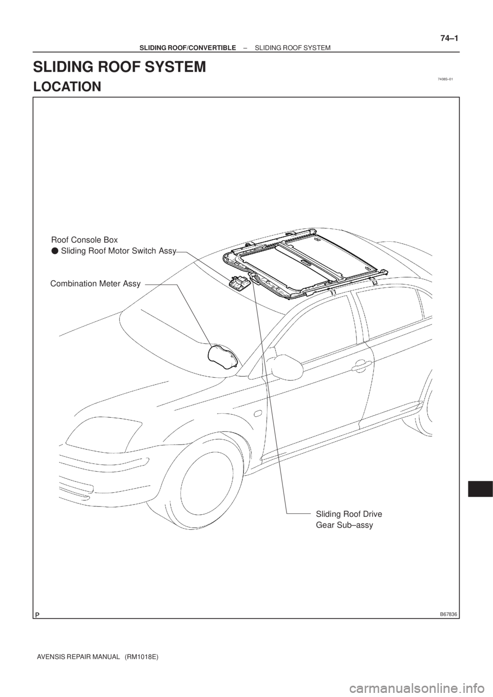
B67836
Combination Meter AssyRoof Console Box
� Sliding Roof Motor Switch Assy
Sliding Roof Drive
Gear Sub±assy
± SLIDING ROOF/CONVERTIBLESLIDING ROOF SYSTEM
74±1
AVENSIS REPAIR MANUAL (RM1018E)
SLIDING ROOF SYSTEM
LOCATION
Page 3304 of 5135
73095±02
B68828
Fuel Lid Opener Switch
B68829
Shaft Strokes
Open 73±30
± THEFT DETERRENT & DOOR LOCKFUEL LID OPENER SYSTEM
AVENSIS REPAIR MANUAL (RM1018E)
INSPECTION
1. INSPECT FUEL LID OPENER SWITCH
(a) Check the switch resistance.
Standard:
Tester ConnectionSwitch PositionSpecified Condition
23OFF10 k� or higher2 ± 3ONBelow 1 �
If the result is not as specified, replace the switch.
2. INSPECT FUEL LID LOCK CONTROL ASSY
(a) Apply battery voltage to the lock control and check the
motor operates in the direction.
Standard:
Measurement ConditionSpecified Condition
Battery positive (+) � Terminal 2
Battery negative (±) � Terminal 1Open direction
If the result is not as specified, replace the lock control assy.
(b) Check the shaft strokes.
Standard: 18.0 mm (0.709 in.) or more
Page 3321 of 5135

INSPECTION
1. INSPECT FRONT DOOR W/MOTOR LOCK ASSY L")
730GW±01
B65427
Unlock
Lock
B65428
UnlockLock
± THEFT DETERRENT & DOOR LOCKPOWER DOOR LOCK CONTROL SYSTEM
73±3
AVENSIS REPAIR MANUAL (RM1018E)
INSPECTION
1. INSPECT FRONT DOOR W/MOTOR LOCK ASSY LH
(W/O DOUBLE DOOR LOCK)
(a) Apply battery voltage to the door lock motor and check
operation.
Standard:
Measurement ConditionSpecified Condition
Battery positive (+) � Terminal 4
Battery negative (±) � Terminal 1Lock
Battery positive (+) � Terminal 1
Battery negative (±) � Terminal 4Unlock
If the result is not as specified, replace the door lock assy.
(b) Driver side only:
Check the resistance of the position switch.
Standard:
Tester ConnectionDoor Lock PositionSpecified Condition
78Lock10 k�or higher7 ± 8UnlockBelow 1 �
If the result is not as specified, replace the door lock assy.
(c) Driver side only:
Check the resistance of the door lock and unlock switch.
Standard:
Tester ConnectionDoor Lock PositionSpecified Condition
7 ± 9LockBelow 1 �
7 ± 9OFF10 k�or higher7 ± 10OFF10 k�or higher
7 ± 10UnlockBelow 1 �
If the result is not as specified, replace the door lock assy.
Page 3322 of 5135

2. INSPECT FRONT DOOR W/MOTOR LOCK ASSY RH
(W/O DOUBLE DOOR L")
B65429
Unlock
Lock
B65430
Unlock
Lock 73±4
± THEFT DETERRENT & DOOR LOCKPOWER DOOR LOCK CONTROL SYSTEM
AVENSIS REPAIR MANUAL (RM1018E)
2. INSPECT FRONT DOOR W/MOTOR LOCK ASSY RH
(W/O DOUBLE DOOR LOCK)
(a) Apply battery voltage to the door lock motor and check
operation.
Standard:
Measurement ConditionSpecified Condition
Battery positive (+) � Terminal 4
Battery negative (±) � Terminal 1Lock
Battery positive (+) � Terminal 1
Battery negative (±) � Terminal 4Unlock
If the result is not as specified, replace the door lock assy.
(b) Driver side only:
Check the door lock and unlock switch resistance.
Standard:
Tester ConnectionDoor Lock PositionSpecified Condition
6 ± 8LockBelow 1 �
6 ± 8OFF10 k�or higher5 ± 8OFF10 k�or higher
5 ± 8UnlockBelow 1 �
If the result is not as specified, replace the door lock assy.
(c) Driver side only:
Check the position switch resistance.
Standard:
Tester ConnectionDoor Lock PositionSpecified Condition
78Lock10 k�or higher7 ± 8UnlockBelow 1 �
If the result is not as specified, replace the door lock assy.
Page 3323 of 5135
B64474
Unlock Lock
B64704
Unlock Lock
± THEFT DETERRENT & DOOR LOCKPOWER DOOR LOCK CONTROL SYSTEM
73±5
AVENSIS REPAIR MANUAL (RM1018E)
3. INSPECT REAR DOOR W/MOTOR LOCK ASSY LH
(W/O DOUBLE DOOR LOCK)
(a) Apply battery voltage to the door lock motor and check
operation.
Standard:
Measurement ConditionSpecified Condition
Battery positive (+) � Terminal 4
Battery negative (±) � Terminal 1Lock
Battery positive (+) � Terminal 1
Battery negative (±) � Terminal 4Unlock
If the result is not as specified, replace the door lock assy.
4. INSPECT REAR DOOR W/MOTOR LOCK ASSY RH
(W/O DOUBLE DOOR LOCK)
(a) Apply battery voltage to the door lock motor and check
operation.
Standard:
Measurement ConditionSpecified Condition
Battery positive (+) � Terminal 4
Battery negative (±) � Terminal 1Lock
Battery positive (+) � Terminal 1
Battery negative (±) � Terminal 4Unlock
If the result is not as specified, replace the door lock assy.
Page 3324 of 5135

5. INSPECT FRONT DOOR W/MOTOR LOCK ASSY LH
(W/ DOUBLE DOOR LOCK)
(a) Apply batte")
B64707
Unlock
Lock 73±6
± THEFT DETERRENT & DOOR LOCKPOWER DOOR LOCK CONTROL SYSTEM
AVENSIS REPAIR MANUAL (RM1018E)
5. INSPECT FRONT DOOR W/MOTOR LOCK ASSY LH
(W/ DOUBLE DOOR LOCK)
(a) Apply battery voltage to the door lock motor and check
operation.
Standard:
Measurement ConditionSpecified Condition
Battery positive (+) � Terminal 4
Battery negative (±) � Terminal 3Lock
Battery positive (+) � Terminal 3
Battery negative (±) � Terminal 4Unlock
If the result is not as specified, replace the door lock assy.
(b) Check the resistance of the position switch.
Standard:
Tester ConnectionDoor Lock PositionSpecified Condition
78Lock10 k�or higher7 ± 8UnlockBelow 1 �
If the result is not as specified, replace the door lock assy.
(c) Check operation of the double lock motor.
(1) Apply battery voltage to the door lock motor and set
it to LOCK.
(2) Apply battery voltage to the double lock motor and
check operation.
Standard:
Measurement ConditionSpecified Condition
Battery positive (+) � Terminal 2
Battery negative (±) � Terminal 1Double Locking System is ON
Battery positive (+) � Terminal 1
Battery negative (±) � Terminal 2Double Locking System is OFF
(3) Check that the doors cannot be unlocked by operat-
ing the control cable while the double locking sys-
tem is ON.
If the result is not as specified, replace the door lock assy.
(d) Check the resistance of the double lock position switch.
Standard:
Tester ConnectionDouble Lock PositionSpecified Condition
56SETBelow 1 �5 ± 6UNSET10 k�or higher
If the result is not as specified, replace the door lock assy.
 Front Power Seat Switch RHLumbar Support Adjuster Motor
Front Pow")

PROBLEM SYMPTOMS TABLE
SymptomSuspected AreaSee Page
AUTO function does not operate1. Sliding roof mot")

INSPECTION
1. INSPECT FUEL LID OPENER SW")

3. INSPECT REAR DOOR W/MOTOR LOCK ASSY LH
(W/O DOUBLE DOOR LO")