Page 3347 of 5135
B66980
B69209
B65138
1
2
3
B61450
±
ENGINE HOOD/DOOR REAR DOOR
75±29
AVENSIS REPAIR MANUAL (RM1018E)
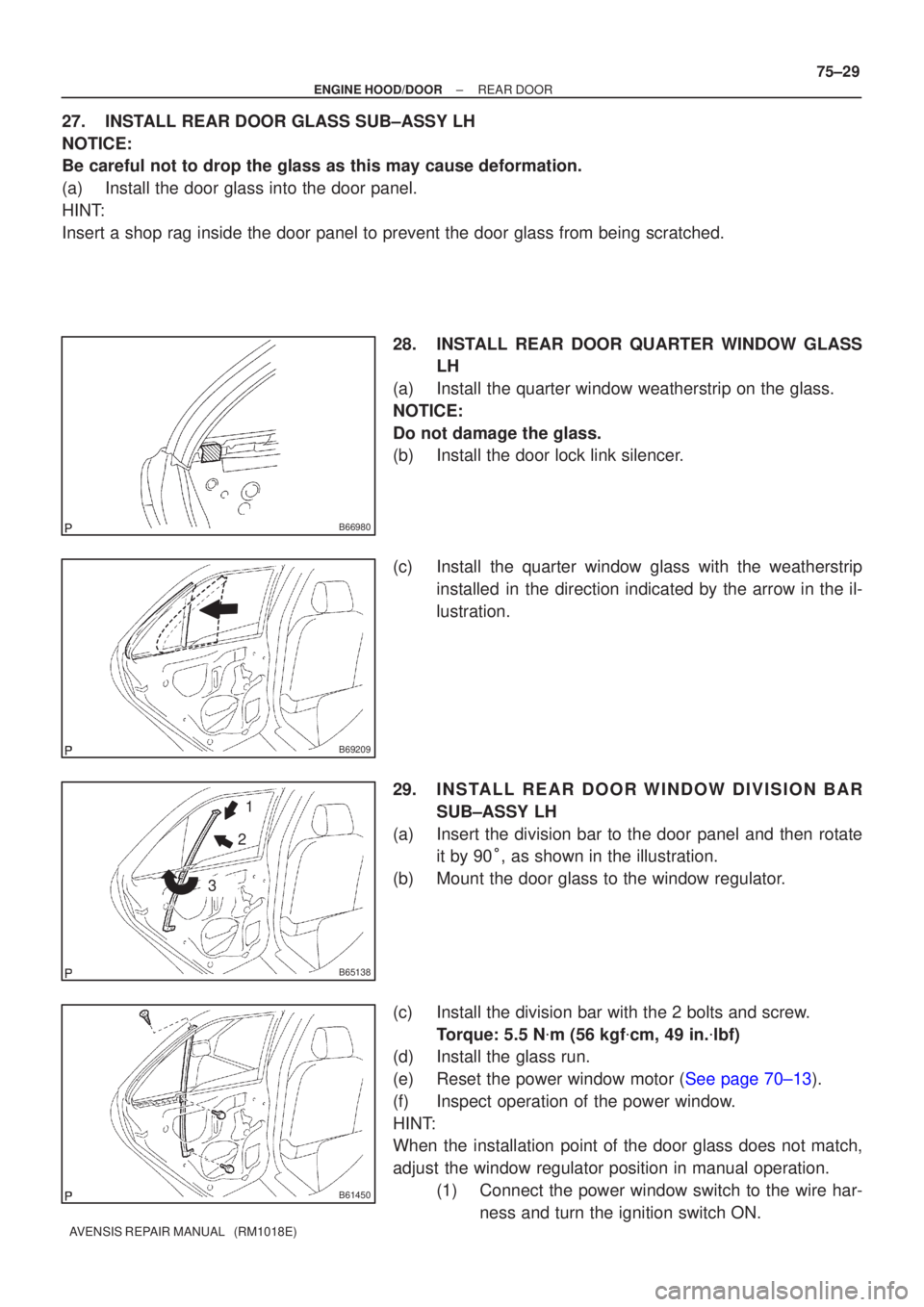
27.INSTALL REAR DOOR GLASS SUB±ASSY LH
NOTICE:
Be careful not to drop the glass as this may cause deformation.
(a)Install the door glass into the door panel.
HINT:
Insert a shop rag inside the door panel to prevent the door glass from b\
eing scratched.
28.INSTALL REAR DOOR QUARTER WINDOW GLASSLH
(a)Install the quarter window weatherstrip on the glass.
NOTICE:
Do not damage the glass.
(b)Install the door lock link silencer.
(c)Install the quarter window glass with the weatherstrip installed in the direction indicated by the arrow in the il-
lustration.
29.INSTALL REAR DOOR WINDOW DIVISION BAR SUB±ASSY LH
(a)Insert the division bar to the door panel and then rotate it by 90 �� as shown in the illustration.
(b)Mount the door glass to the window regulator.
(c)Install the division bar with the 2 bolts and screw. Torque: 5.5 N �m (56 kgf �cm, 49 in. �lbf)
(d)Install the glass run.
(e)Reset the power window motor (See page 70±13).
(f) Inspect operation of the power window.
HINT:
When the installation point of the door glass does not match,
adjust the window regulator position in manual operation.
(1) Connect the power window switch to the wire har-ness and turn the ignition switch ON.
Page 3353 of 5135
B67991
Rear Door Lock w/ Motor Assy LH
26 (265, 19)
26 (265, 19)
5.5 (56, 49 in.´lbf)
30 (306, 22)
Rear Door Check Assy
Rear Door Weatherstrip LHRear Door Belt Moulding LH Rear Door Outside Handle Frame Sub±assy LHRear Door Outside Handle Cover LH
Rear Door Outside Handle Assy LH
Rear Door Outside Handle Pad Rear Rear Door Outside Handle Pad Front
Child Protector
Lock Hole PlugDoor Lock Wire Harness Packing
�
5.0 (51, 44 in.´lbf)�
Clip
Cushion Rubber
Cushion Rubber
Rear Door Hinge Assy Lower LH Rear Door Hinge Assy Upper LH
Rear Door Speaker Assy No. 2Door Lock Link Silencer
: Specified torqueN´m (kgf´cm, ft´lbf)
�
Precoated Part Non±reusable part ��Front Door Service Hole Cover �
Butyl Tape�
± ENGINE HOOD/DOORREAR DOOR
75±19
AVENSIS REPAIR MANUAL (RM1018E)
Page 3358 of 5135
B66894
B56613
1
2
B70122
Screw
B57102
B68928
75±12
± ENGINE HOOD/DOORFRONT DOOR
AVENSIS REPAIR MANUAL (RM1018E)
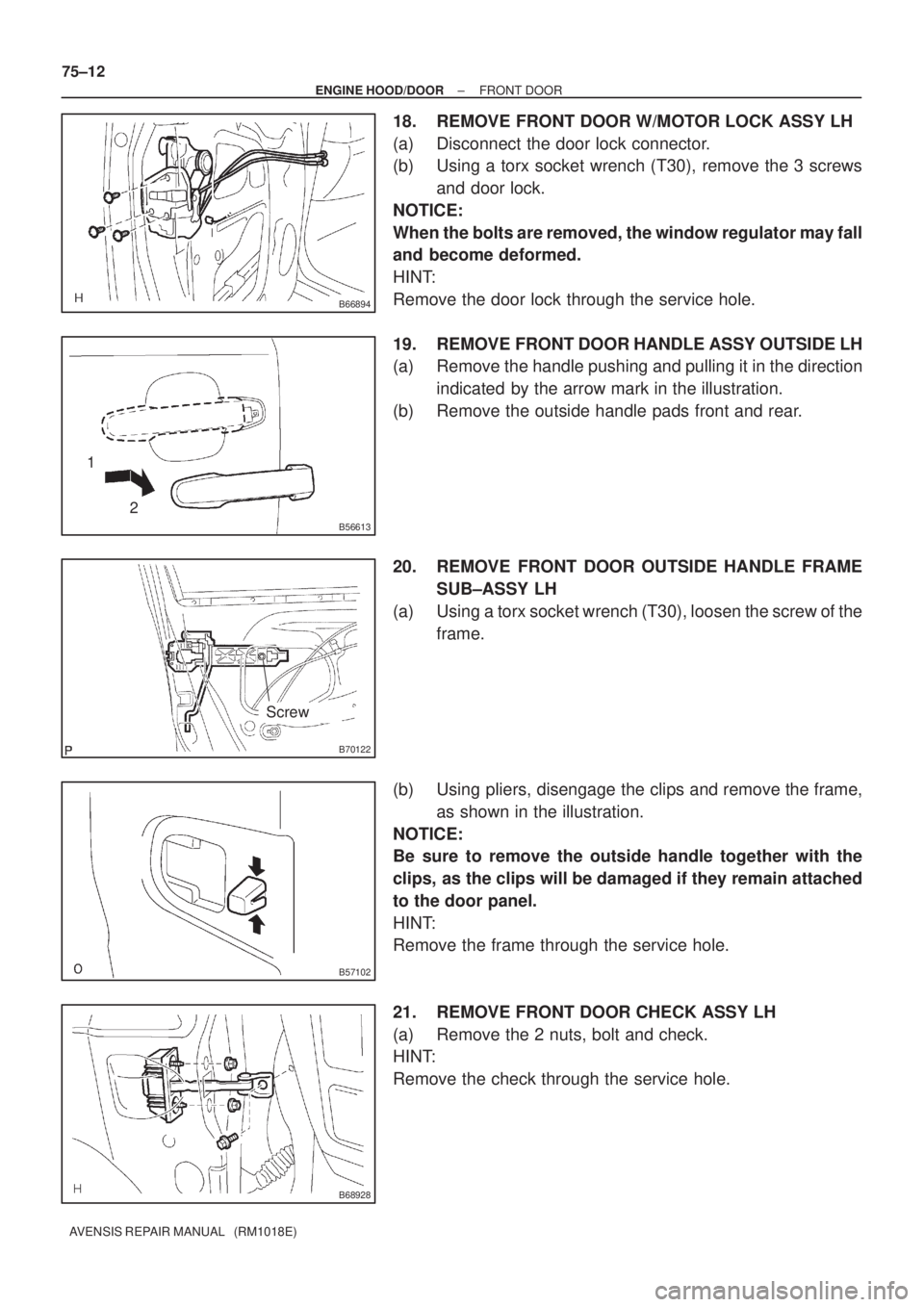
18. REMOVE FRONT DOOR W/MOTOR LOCK ASSY LH
(a) Disconnect the door lock connector.
(b) Using a torx socket wrench (T30), remove the 3 screws
and door lock.
NOTICE:
When the bolts are removed, the window regulator may fall
and become deformed.
HINT:
Remove the door lock through the service hole.
19. REMOVE FRONT DOOR HANDLE ASSY OUTSIDE LH
(a) Remove the handle pushing and pulling it in the direction
indicated by the arrow mark in the illustration.
(b) Remove the outside handle pads front and rear.
20. REMOVE FRONT DOOR OUTSIDE HANDLE FRAME
SUB±ASSY LH
(a) Using a torx socket wrench (T30), loosen the screw of the
frame.
(b) Using pliers, disengage the clips and remove the frame,
as shown in the illustration.
NOTICE:
Be sure to remove the outside handle together with the
clips, as the clips will be damaged if they remain attached
to the door panel.
HINT:
Remove the frame through the service hole.
21. REMOVE FRONT DOOR CHECK ASSY LH
(a) Remove the 2 nuts, bolt and check.
HINT:
Remove the check through the service hole.
Page 3359 of 5135
B68928
Adhesive
B70122
Screw
B64044
1 2
± ENGINE HOOD/DOORFRONT DOOR
75±13
AVENSIS REPAIR MANUAL (RM1018E)
22. REMOVE FRONT DOOR WEATHERSTRIP LH
(a) Using a clip remover, disengage the clips and remove the weatherstrip.
HINT:
If the clips are damaged, replace them with new clips.
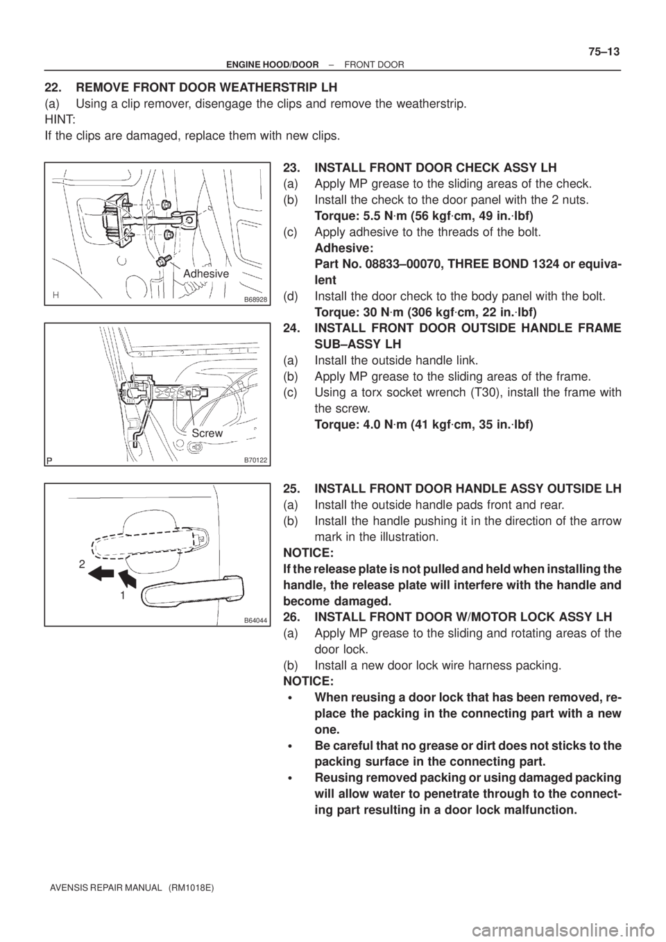
23. INSTALL FRONT DOOR CHECK ASSY LH
(a) Apply MP grease to the sliding areas of the check.
(b) Install the check to the door panel with the 2 nuts.
Torque: 5.5 N�m (56 kgf�cm, 49 in.�lbf)
(c) Apply adhesive to the threads of the bolt.
Adhesive:
Part No. 08833±00070, THREE BOND 1324 or equiva-
lent
(d) Install the door check to the body panel with the bolt.
Torque: 30 N�m (306 kgf�cm, 22 in.�lbf)
24. INSTALL FRONT DOOR OUTSIDE HANDLE FRAME
SUB±ASSY LH
(a) Install the outside handle link.
(b) Apply MP grease to the sliding areas of the frame.
(c) Using a torx socket wrench (T30), install the frame with
the screw.
Torque: 4.0 N�m (41 kgf�cm, 35 in.�lbf)
25. INSTALL FRONT DOOR HANDLE ASSY OUTSIDE LH
(a) Install the outside handle pads front and rear.
(b) Install the handle pushing it in the direction of the arrow
mark in the illustration.
NOTICE:
If the release plate is not pulled and held when installing the
handle, the release plate will interfere with the handle and
become damaged.
26. INSTALL FRONT DOOR W/MOTOR LOCK ASSY LH
(a) Apply MP grease to the sliding and rotating areas of the
door lock.
(b) Install a new door lock wire harness packing.
NOTICE:
�When reusing a door lock that has been removed, re-
place the packing in the connecting part with a new
one.
�Be careful that no grease or dirt does not sticks to the
packing surface in the connecting part.
�Reusing removed packing or using damaged packing
will allow water to penetrate through to the connect-
ing part resulting in a door lock malfunction.
Page 3361 of 5135
B66968
B62423
1
2
B62422
B61441
±
ENGINE HOOD/DOOR FRONT DOOR
75±15
AVENSIS REPAIR MANUAL (RM1018E)
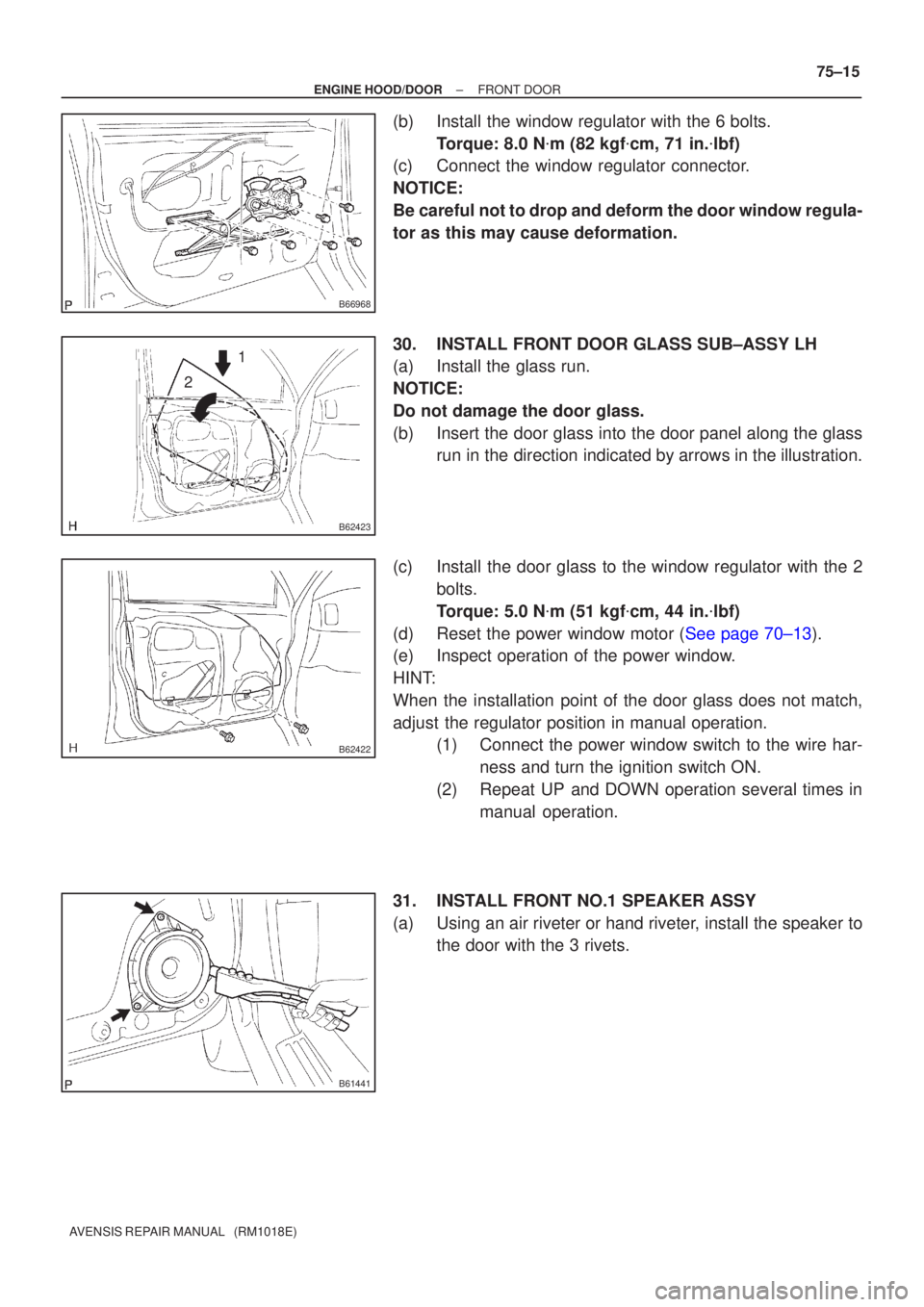
(b)Install the window regulator with the 6 bolts.
Torque: 8.0 N �m (82 kgf �cm, 71 in. �lbf)
(c)Connect the window regulator connector.
NOTICE:
Be careful not to drop and deform the door window regula-
tor as this may cause deformation.
30.INSTALL FRONT DOOR GLASS SUB±ASSY LH
(a)Install the glass run.
NOTICE:
Do not damage the door glass.
(b)Insert the door glass into the door panel along the glass run in the direction indicated by arrows in the illustration.
(c)Install the door glass to the window regulator with the 2 bolts.
Torque: 5.0 N �m (51 kgf �cm, 44 in. �lbf)
(d)Reset the power window motor (See page 70±13).
(e) Inspect operation of the power window.
HINT:
When the installation point of the door glass does not match,
adjust the regulator position in manual operation. (1) Connect the power window switch to the wire har-
ness and turn the ignition switch ON.
(2) Repeat UP and DOWN operation several times in manual operation.
31. INSTALL FRONT NO.1 SPEAKER ASSY
(a) Using an air riveter or hand riveter, install the speaker to the door with the 3 rivets.
Page 3367 of 5135
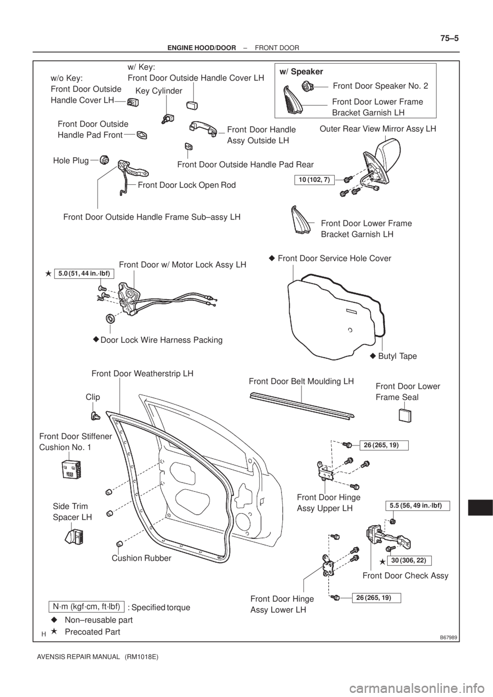
B67989
Front Door Outside Handle Frame Sub±assy LHw/ Key:
Front Door Outside Handle Cover LH
Front Door Handle
Assy Outside LH
Front Door Outside Handle Pad Rear Front Door Outside
Handle Pad Front
Hole Plug
Front Door Lock Open Rod
Front Door w/ Motor Lock Assy LH
Door Lock Wire Harness Packing �5.0 (51, 44 in.´lbf)
Front Door Belt Moulding LH
Front Door Hinge
Assy Upper LH
Front Door Check Assy
30 (306, 22)�
5.5 (56, 49 in.´lbf)
Front Door Hinge
Assy Lower LH26 (265, 19)
Front Door Weatherstrip LH
Cushion RubberFront Door Lower Frame
Bracket Garnish LH Outer Rear View Mirror Assy LH
Front Door Speaker No. 2
Front Door Service Hole Cover �
: Specified torqueN´m (kgf´cm, ft´lbf)
�
Precoated Part Non±reusable part �Clip
26 (265, 19)
Front Door Lower
Frame Seal
�
Butyl Tape
�
10 (102, 7)
Front Door Stiffener
Cushion No. 1
Side Trim
Spacer LH
Key Cylinder
w/o Key:
Front Door Outside
Handle Cover LHw/ Speaker
Front Door Lower Frame
Bracket Garnish LH
± ENGINE HOOD/DOORFRONT DOOR
75±5
AVENSIS REPAIR MANUAL (RM1018E)
Page 3379 of 5135
7408W±01
± SLIDING ROOF/CONVERTIBLESLIDING ROOF SYSTEM
74±7
AVENSIS REPAIR MANUAL (RM1018E)
RESET
1. RESET SLIDING ROOF MOTOR
(a) If the AUTO operation function does not operate, reset the sliding roof motor as follows:
(1) Press the sliding roof switch on the TILT UP side and hold it until the sliding roof motor stops.
Then release the switch and leave it untouched for 10 seconds or more.
(2) Press the sliding roof switch on the TILT UP side again for 10 seconds or more and hold it until
the sliding roof glass stops at the fully open and up position.
(3) Release the switch, press it again within 5 seconds and hold it until a series of movements indi-
cated below have been completed:
Fully closing � Fully opening � Fully closing
HINT:
When the battery terminal is disconnected or after the jam protection function has operated, the sliding roof
motor ECU may not detect the position of the roof glass. If the AUTO operation function is still disabled even
after the sliding roof motor is reset, the Hall IC (built in the sliding roof motor) for detecting the roof glass
position may be malfunctioning.
Page 3380 of 5135
7408V±01
B67892
1
4 3
2
B67891
10
9876 54321
���
A05
115
74±6
±
SLIDING ROOF/CONVERTIBL ESLIDING ROOF SYSTEM
A VENSIS RE PAIR MANUAL (RM1018E)
INSPECTION
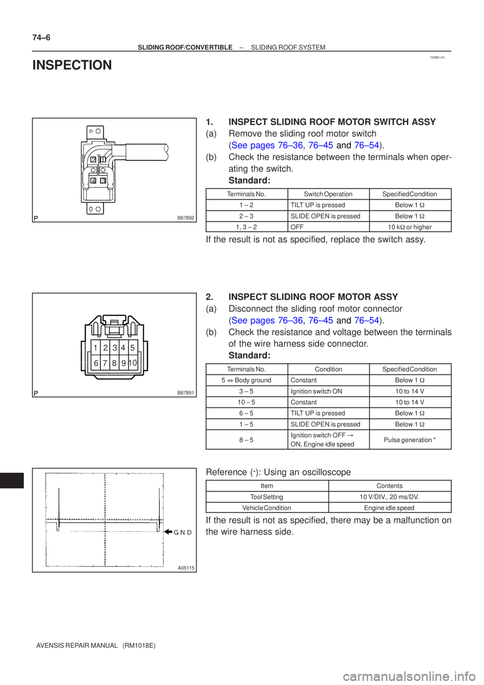
1. INSPEC T SLIDING ROOF MO TOR SWITCH ASSY
(a ) Remove the sliding roof motor switch
( See pages 76±36 , 76±45 and 76±54 ).
(b ) Check the resistance between the terminals when oper-
ating the switch.
Standard:
T erminal s No.Switch OperationSpecified Condition
1 ± 2TI LT UP is pressedBelow 1 �
2 ± 3SLIDE OPEN is pressedBelow 1 �
1, 3 ± 2OFF10 k� or higher
If the result is not as specified, replace the switch ass y.
2 . INSPECT SLIDING ROOF MO TOR ASSY
(a ) Disconnect the sliding roof motor connector
( See pages 76±36 , 76±45 and 76±54 ).
(b) Check the resistance and voltage between the terminals of the wire harness side connector.
Standard:
Terminals No.ConditionSpecified Condition
5 � Body groundConstantBelow 1 �
3 ± 5Ignition switch ON10 to 14 V
10 ± 5Constant10 to 14 V
6 ± 5TILT UP is pressedBelow 1 �
1 ± 5SLIDE OPEN is pressedBelow 1 �
8 ± 5Ignition switch OFF �
ON, Engine idle speedPulse generation *
Reference (*): Using an oscilloscope
ItemContents
Tool Setting10 V/DIV., 20 ms/DV.
Vehicle ConditionEngine idle speed
If the result is not as specified, there may be a malfunction on
the wire harness side.