Page 685 of 5135

A82882
Fuel Pressure
Engine Speed
Normal
Abnormal P0087 Malfunction Detection
± DIAGNOSTICSECD SYSTEM (1CD±FTV)
05±559
AVENSIS REPAIR MANUAL (RM1018E)
MONITOR DESCRIPTION
P0087 (Fuel pressure sensor output stays at fixed value):
Under normal condition, internal fuel pressure of the common rail usually fluctuates 1 to 2 MPa (10 to 20
kgf/cm
2, 145 to 290 psi) even if the driving condition is constant. The internal fuel pressure is approximately
30 to 40 MPa (306 to 408 kgf/cm
2, 4,351 to 5,801 psi) at idling, and it increases to approx. 50 to 100 MPa
(510 to 1,020 kgf/cm
2, 7,251 to 14,503 psi) when running the engine at 2,500 rpm. This DTC code is set if
there is no fluctuation at the internal fuel pressure.
If this DTC is present, the ECM enters fail±safe mode and limits the engine power. The fail±safe mode will
continue until the ignition switch is turned OFF.
P0190, P0192 and P0193 (Open or short in fuel pressure sensor circuit):
These DTCs are set if the fuel pressure sensor output voltage is out of the standard range. The DTCs stand
for open or short malfunction of the sensor circuit.
If these DTCs are present, the ECM enters fail±safe mode and limits the engine power. The fail±safe mode
will continue until the ignition switch is turned OFF.
MONITOR STRATEGY
P0087:
Required sensorsFuel pressure sensor
Frequency of operationContinuous
Duration1 sec.
CHK ENG operation1 driving cycle
P0190:
Required sensorsFuel pressure sensor
Frequency of operationContinuous
Duration0.5 sec.
CHK ENG operation1 driving cycle
P0192:
Required sensorsFuel pressure sensor
Frequency of operationContinuous
Duration0.5 sec.
CHK ENG operation1 driving cycle
Page 686 of 5135
05±560
± DIAGNOSTICSECD SYSTEM (1CD±FTV)
AVENSIS REPAIR MANUAL (RM1018E)
P0193:
Required sensorsFuel pressure sensor
Frequency of operationContinuous
Duration0.5 sec.
CHK ENG operation1 driving cycle
TYPICAL ENABLING CONDITIONS
P0087:
ItemSpecificationItemMinimumMaximum
Engine speed500 rpm±
Battery voltage8 V±
Fuel quantify5 mm3/st±
The monitor will not run if the fuel pressure sensor circuit (P0190, P0192 and P0193) is malfunction
TYPICAL MALFUNCTION THRESHOLDS
P0087:
Detection CriteriaThreshold
Changing value of fuel pressureVirtually no fluctuation
P0190:
Detection CriteriaThreshold
Fuel pressure sensor output voltageLess than 0.55 V or more than 4.9 V
P0192:
Detection CriteriaThreshold
Fuel pressure sensor output voltageLess than 0.55 V
P0193:
Detection CriteriaThreshold
Fuel pressure sensor output voltageMore than 4.9 V
Page 689 of 5135

A66060
E13
ECM ConnectorE12
VN(+)E1(±)
A82974
VRV Signal Waveforms
GND
5V/
Division
1 msec./ Division
05±554
±
DIAGNOSTICS ECD SYSTEM(1CD±FTV)
AVENSIS REPAIR MANUAL (RM1018E)
DTCP0045TURBO/SUPER CHARGER BOOST CONTROL SOLENOID CIRCUIT / OPEN
CIRCUIT DESCRIPTION
DTC No.DTC Detection ConditionTrouble Area
P0045Open or short in VRV circuit for 0.5sec. or more
(1 trip detection logic)�VRV
� Open or short in VRV circuit
� ECM
WIRING DIAGRAM
Refer to DTC P0234 on page 05±612.
INSPECTION PROCEDURE
HINT:
Read freeze frame data using �����\b��������
�� . Freeze frame data records the engine conditions when
a malfunction is detected. When troubleshooting, it is useful for determi\
ning whether the vehicle was running
or stopped, the engine was warmed up or not, etc. at the time of the malfu\
nction.
1INSPECT VACUUM REGULATING VALVE ASSY (See page 12±16)
NGREPLACE VACUUM REGULATING VALVE ASSY
OK
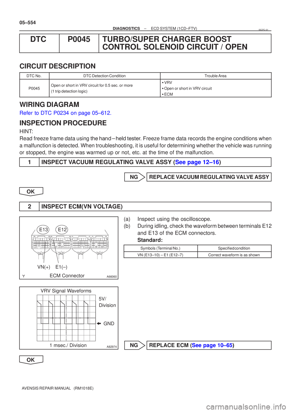
2INSPECT ECM(VN VOLTAGE)
(a)Inspect using the oscilloscope.
(b)During idling, check the waveform between terminals E12 and E13 of the ECM connectors.
Standard:
Symbols (Terminal No.)Specified condition
VN (E13±10) ± E1 (E12±7)Correct waveform is as shown
NGREPLACE ECM (See page 10±65)
OK
05CPC±01
Page 692 of 5135
± DIAGNOSTICSECD SYSTEM (1CD±FTV)
05±643
AVENSIS REPAIR MANUAL (RM1018E)
DTC P0504 BRAKE SWITCH ºAº/ºBº CORRELATION
CIRCUIT DESCRIPTION
In this system, the signal of the stop lamp switch is used to judge whether the acceleration system is abnor-
mal or not.
The stop lamp switch has a duplex system (signals STP and ST1±) to memorize the abnormality when the
signals of depressing and releasing the brake pedal are detected simultaneously.
HINT:
Normal condition is as shown in the table.
SignalBrake pedal releasedIn transitionBrake pedal depressed
STPOFFONON
ST1±ONONOFF
DTC No.DTC Detection ConditionTrouble Area
P0504
Conditions (a), (b) and (c) continue for 0.5 sec. or more
(1 trip detection logic):
(a) Ignition switch ON
(b) Brake pedal released
(c) STP signal is OFF when the ST1± signal is OFF
�Short in stop lamp switch signal circuit
�Stop lamp switch
�ECM
05CPW±01
Page 694 of 5135

A72924
FreePushed in
432
1
Stop Lamp Switch
A80995
Brake Pedal
Depressed Brake Pedal
Released
ST1± (+)
E1 (±)
ECM ConnectorE12
E10
±
DIAGNOSTICS ECD SYSTEM(1CD±FTV)
05±645
AVENSIS REPAIR MANUAL (RM1018E)
1CHECK OPERATION OF STOP LIGHT
(a)Check if the stop lights go on and off normally when the brake pedal is depressed and released.
NGREPAIR OR REPLACE STOP LAMP SWITCHCIRCUIT
OK
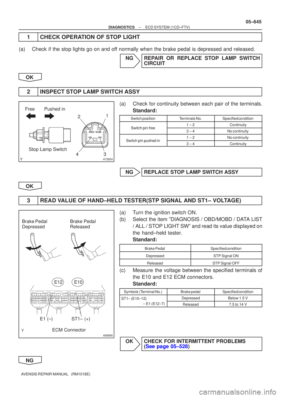
2INSPECT STOP LAMP SWITCH ASSY
(a)Check for continuity between each pair of the terminals. Standard:
Switch positionTerminals No.Specified condition
Switchpinfree1 ± 2ContinuitySwitch pin free3 ± 4No continuity
Switchpinpushedin1 ± 2No continuitySwitch pin pushed in3 ± 4Continuity
NGREPLACE STOP LAMP SWITCH ASSY
OK
3READ VALUE OF HAND±HELD TESTER(STP SIGNAL AND ST1± VOLTAGE)
(a)Turn the ignition switch ON.
(b)Select the item ºDIAGNOSIS / OBD/MOBD / DATA LIST / ALL / STOP LIGHT SWº and read its value displayed on
the hand±held tester.
Standard:
Brake PedalSpecified condition
DepressedSTP Signal ON
ReleasedSTP Signal OFF
(c)Measure the voltage between the specified terminals ofthe E10 and E12 ECM connectors.
Standard:
Symbols (Terminal No.)Brake pedalSpecified condition
ST1± (E10±12) DepressedBelow 1.5 VST1 (E1012)
± E1 (E12±7)
Released7.5 to 14 V
OKCHECK FOR INTERMITTENT PROBLEMS (See page 05±528)
NG
Page 696 of 5135

A79413
From
Speed SensorSkid
Control
ECU4±Pulse
Combination
Meter4±Pulse
ECM 05±640
± DIAGNOSTICSECD SYSTEM (1CD±FTV)
AVENSIS REPAIR MANUAL (RM1018E)
DTC P0500 VEHICLE SPEED SENSOR ºAº
CIRCUIT DESCRIPTION
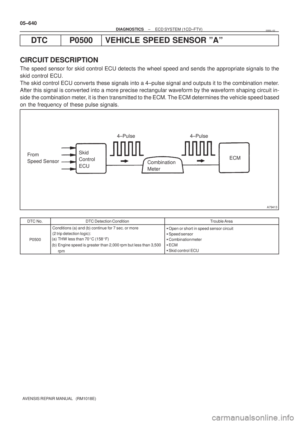
The speed sensor for skid control ECU detects the wheel speed and sends the appropriate signals to the
skid control ECU.
The skid control ECU converts these signals into a 4±pulse signal and outputs it to the combination meter.
After this signal is converted into a more precise rectangular waveform by the waveform shaping circuit in-
side the combination meter, it is then transmitted to the ECM. The ECM determines the vehicle speed based
on the frequency of these pulse signals.
DTC No.DTC Detection ConditionTrouble Area
P0500
Conditions (a) and (b) continue for 7 sec. or more
(2 trip detection logic):
(a) THW less than 70�C (158�F)
(b) Engine speed is greater than 2,000 rpm but less than 3,500
rpm�Open or short in speed sensor circuit
�Speed sensor
�Combination meter
�ECM
�Skid control ECU
05B5L±03
Page 697 of 5135
A81008
ECM
E10 17
V±W
C11
Combination
Meter Assy
(RHD)
V±W
18
J20H
J/C
SP1
(RHD) J20
H
(LHD) J10
H
(LHD)J10
H
±
DIAGNOSTICS ECD SYSTEM(1CD±FTV)
05±641
AVENSIS REPAIR MANUAL (RM1018E)
WIRING DIAGRAM
INSPECTION PROCEDURE
HINT:
Read freeze frame data using �����\b��������
�� . Freeze frame data records the engine conditions when
a malfunction is detected. When troubleshooting, it is useful for determi\
ning whether the vehicle was running
or stopped, the engine was warmed up or not, etc. at the time of the malfu\
nction.
1CHECK OPERATION OF SPEEDOMETER
(a)Drive the vehicle and check if the operation of the speedometer in the combination meter is normal.
HINT:
The vehicle speed sensor is operating normally if the speedometer displa\
y is normal.
NGCHECK SPEEDOMETER CIRCUIT (See page 05±1510)
OK
Page 699 of 5135

A81482
Reduction GearIntake Shutter Control Motor
Intake Shutter Valve
Intake Shutter Valve
Fully Opened Switch Intake Shutter Internal Structure
ON
OFF
CLOSE
OPEN
± DIAGNOSTICSECD SYSTEM (1CD±FTV)
05±633
AVENSIS REPAIR MANUAL (RM1018E)
DTC P0488 EXHAUST GAS RECIRCULATION
THROTTLE POSITION CONTROL
RANGE/PERFORMANCE
CIRCUIT DESCRIPTION
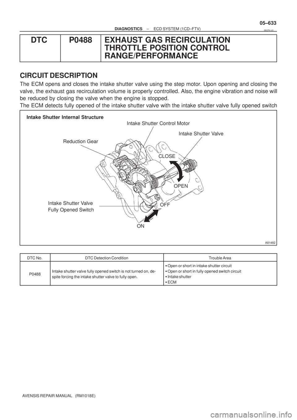
The ECM opens and closes the intake shutter valve using the step motor. Upon opening and closing the
valve, the exhaust gas recirculation volume is properly controlled. Also, the engine vibration and noise will
be reduced by closing the valve when the engine is stopped.
The ECM detects fully opened of the intake shutter valve with the intake shutter valve fully opened switch
DTC No.DTC Detection ConditionTrouble Area
P0488Intake shutter valve fully opened switch is not turned on, de-
spite forcing the intake shutter valve to fully open.
�Open or short in intake shutter circuit
�Open or short in fully opened switch circuit
�Intake shutter
�ECM
05CPV±01