Page 706 of 5135
A81006
ECM
E3
EGR Valve Assy
G
EG+A 6
E12
Y±G
R±L
G±BE12
E12
E125
4
3EG±A
EG+B
EG±B 6
4
3
1From EFI MAIN Relay
5
2B±W
B±W
B±W
± DIAGNOSTICSECD SYSTEM (1CD±FTV)
05±629
AVENSIS REPAIR MANUAL (RM1018E)
DTC P0400 EXHAUST GAS RECIRCULATION FLOW
DTC P0403 EXHAUST GAS RECIRCULATION CONTROL
CIRCUIT
CIRCUIT DESCRIPTION
DTC No.DTC Detection ConditionTrouble Area
P0400Mass air flow rate is not changed when turning on EGR valve�EGR valve assy
�Open or short in EGR circuit
P0403EGR valve assy motor malfunction
�Oen or short in EGR circuit
�EGR passage
�ECM
WIRING DIAGRAM
INSPECTION PROCEDURE
HINT:
Read freeze frame data using ��� �� ������ �����
� Freeze frame data records the engine conditions when
a malfunction is detected. When troubleshooting, it is useful for determining whether the vehicle was running
or stopped, the engine was warmed up or not, etc. at the time of the malfunction.
05CPU±01
Page 710 of 5135

A81017
GeneratorGlow Plug ECMGLOW
Relay Battery
A81018
Ignition Switch
Glow Plug
Engine Speed
Starting EngineAfter Glow Time OFFOFF ON ON
OFF After Glow System
(sec.)
1
020
6840
104(�C)
(�F)
After Glow Time
Engine Coolant Temperature 120 05±622
± DIAGNOSTICSECD SYSTEM (1CD±FTV)
AVENSIS REPAIR MANUAL (RM1018E)
DTC P0380 GLOW PLUG/HEATER CIRCUIT ºAº
CIRCUIT DESCRIPTION
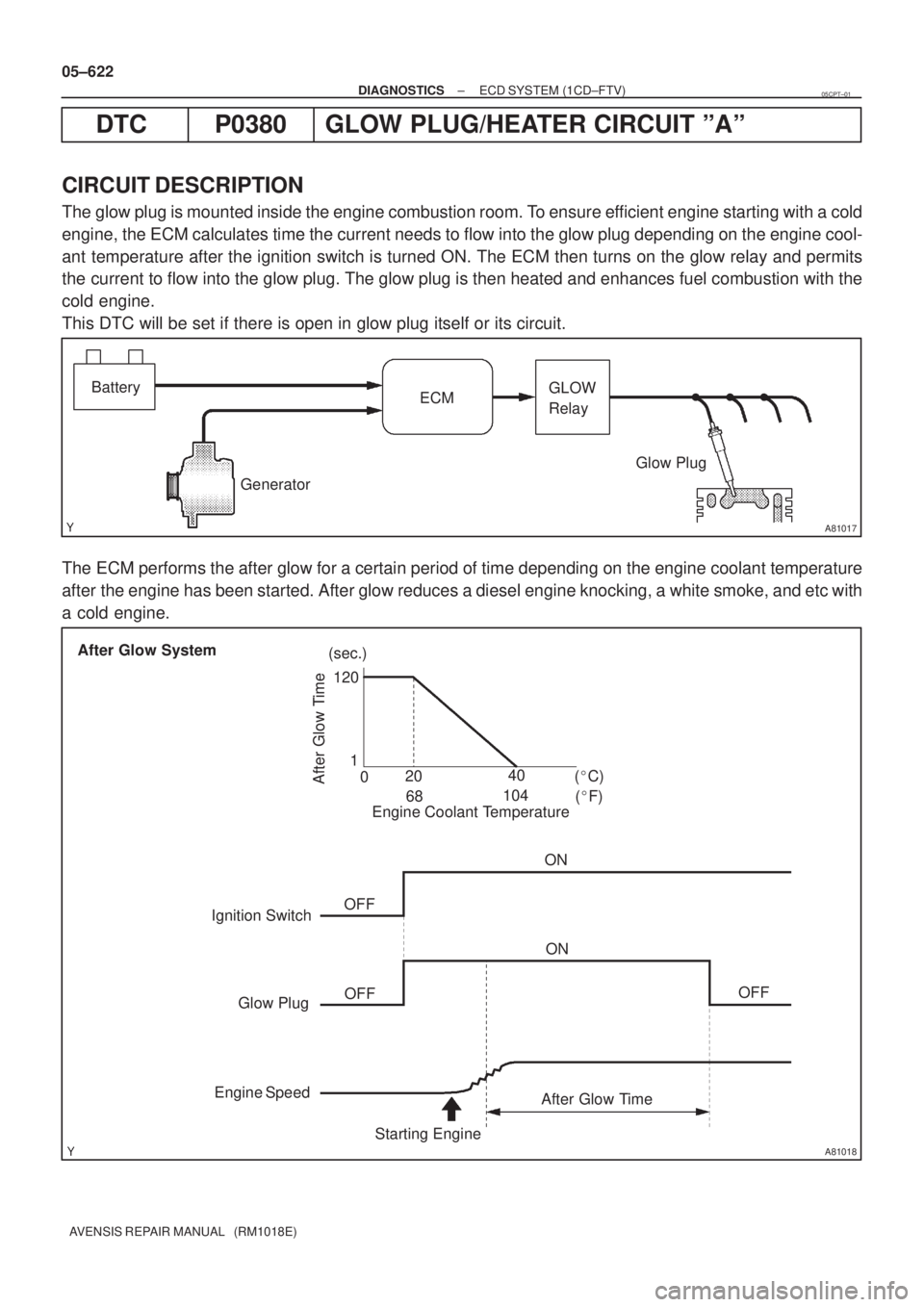
The glow plug is mounted inside the engine combustion room. To ensure efficient engine starting with a cold
engine, the ECM calculates time the current needs to flow into the glow plug depending on the engine cool-
ant temperature after the ignition switch is turned ON. The ECM then turns on the glow relay and permits
the current to flow into the glow plug. The glow plug is then heated and enhances fuel combustion with the
cold engine.
This DTC will be set if there is open in glow plug itself or its circuit.
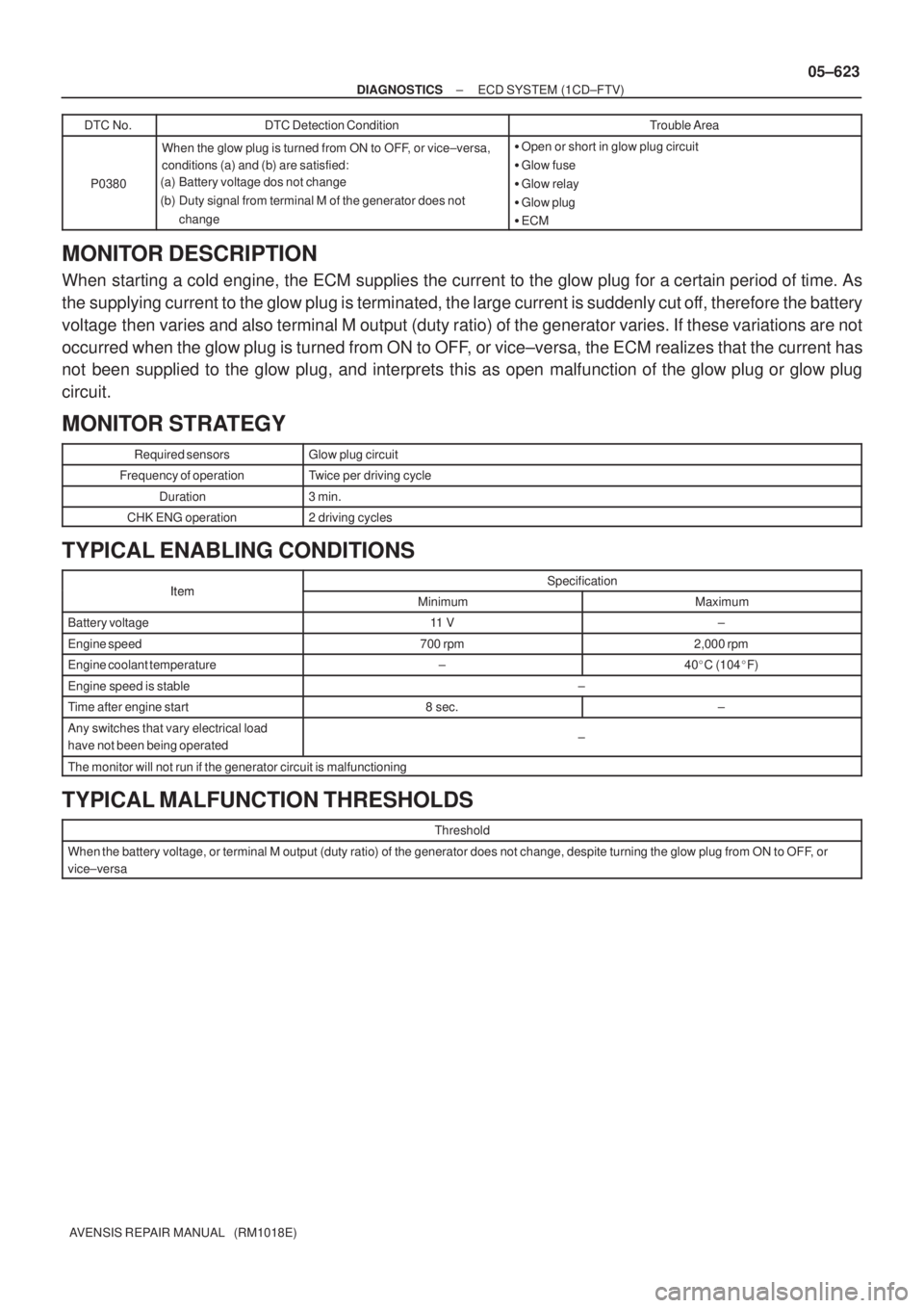
The ECM performs the after glow for a certain period of time depending on the engine coolant temperature
after the engine has been started. After glow reduces a diesel engine knocking, a white smoke, and etc with
a cold engine.
05CPT±01
Page 711 of 5135

± DIAGNOSTICSECD SYSTEM (1CD±FTV)
05±623
AVENSIS REPAIR MANUAL (RM1018E)DTC No.
DTC Detection ConditionTrouble Area
P0380
When the glow plug is turned from ON to OFF, or vice±versa,
conditions (a) and (b) are satisfied:
(a) Battery voltage dos not change
(b) Duty signal from terminal M of the generator does not
change�Open or short in glow plug circuit
�Glow fuse
�Glow relay
�Glow plug
�ECM
MONITOR DESCRIPTION
When starting a cold engine, the ECM supplies the current to the glow plug for a certain period of time. As
the supplying current to the glow plug is terminated, the large current is suddenly cut off, therefore the battery
voltage then varies and also terminal M output (duty ratio) of the generator varies. If these variations are not
occurred when the glow plug is turned from ON to OFF, or vice±versa, the ECM realizes that the current has
not been supplied to the glow plug, and interprets this as open malfunction of the glow plug or glow plug
circuit.
MONITOR STRATEGY
Required sensorsGlow plug circuit
Frequency of operationTwice per driving cycle
Duration3 min.
CHK ENG operation2 driving cycles
TYPICAL ENABLING CONDITIONS
ItemSpecificationItemMinimumMaximum
Battery voltage11 V±
Engine speed700 rpm2,000 rpm
Engine coolant temperature±40�C (104�F)
Engine speed is stable±
Time after engine start8 sec.±
Any switches that vary electrical load
have not been being operated±
The monitor will not run if the generator circuit is malfunctioning
TYPICAL MALFUNCTION THRESHOLDS
Threshold
When the battery voltage, or terminal M output (duty ratio) of the generator does not change, despite turning the glow plug from ON to OFF, or
vice±versa
Page 714 of 5135

A33913
A80987
Engine Room R/B No. 3GLOW
Fuse
B08263
OhmmeterContinuity
05±626
±
DIAGNOSTICS ECD SYSTEM(1CD±FTV)
AVENSIS REPAIR MANUAL (RM1018E)
2CHECK GLOW PLUG RELAY ASSY
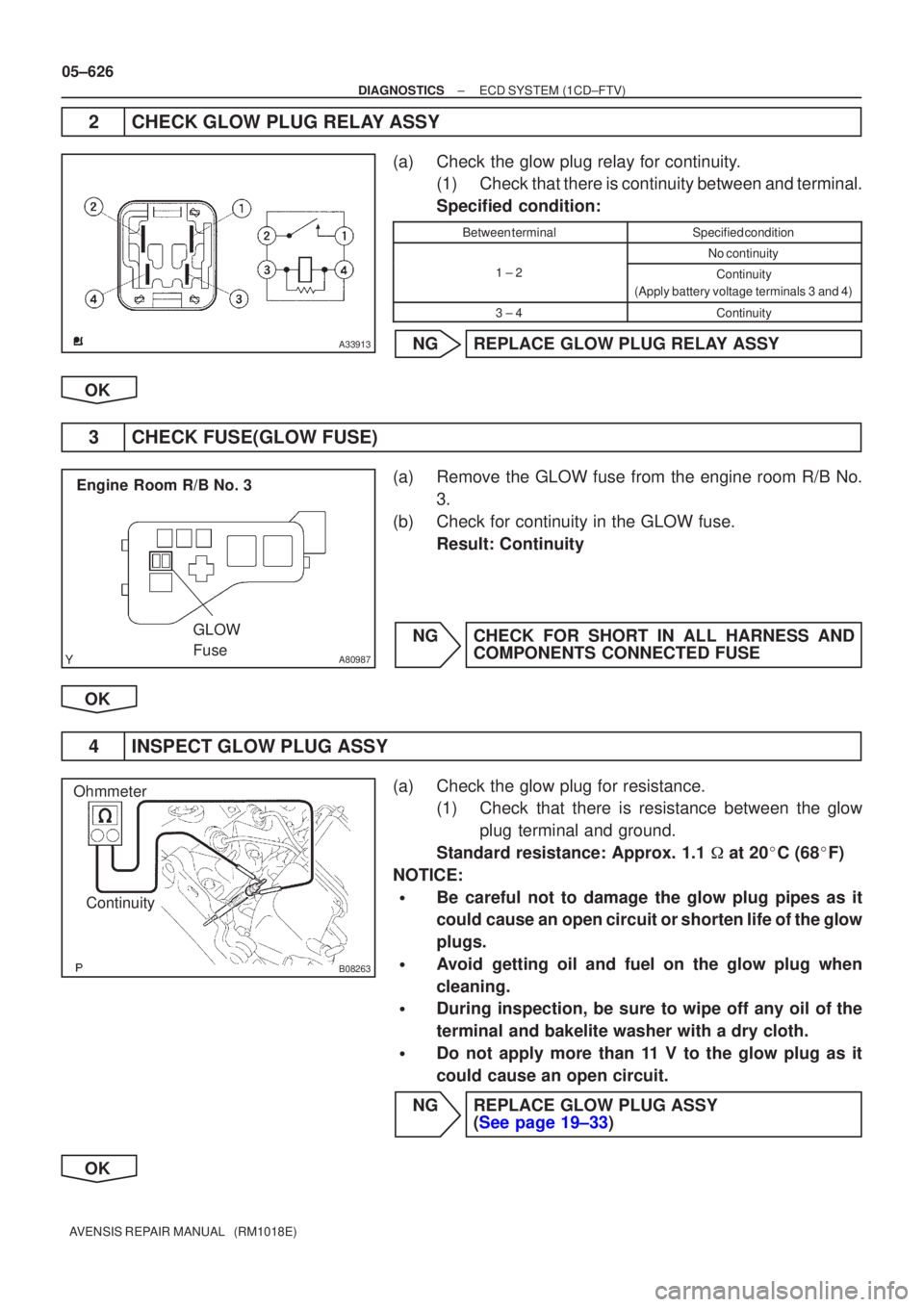
(a)Check the glow plug relay for continuity. (1)Check that there is continuity between and terminal.
Specified condition:
Between terminalSpecified condition
No continuity
1 ± 2Continuity
(Apply battery voltage terminals 3 and 4)
3 ± 4Continuity
NGREPLACE GLOW PLUG RELAY ASSY
OK
3CHECK FUSE(GLOW FUSE)
(a)Remove the GLOW fuse from the engine room R/B No. 3.
(b)Check for continuity in the GLOW fuse. Result: Continuity
NGCHECK FOR SHORT IN ALL HARNESS AND COMPONENTS CONNECTED FUSE
OK
4INSPECT GLOW PLUG ASSY
(a)Check the glow plug for resistance. (1)Check that there is resistance between the glow
plug terminal and ground.
Standard resistance: Approx. 1.1 � at 20 �C (68 �F)
NOTICE:
�Be careful not to damage the glow plug pipes as it
could cause an open circuit or shorten life of the glow
plugs.
�Avoid getting oil and fuel on the glow plug when
cleaning.
�During inspection, be sure to wipe off any oil of the
terminal and bakelite washer with a dry cloth.
�Do not apply more than 11 V to the glow plug as it
could cause an open circuit.
NGREPLACE GLOW PLUG ASSY (See page 19±33)
OK
Page 717 of 5135

A81512
G and NE Signal Waveforms5 V/
Division
G 20 msec./Division (Idling)
NE
A64984
Camshaft Position Sensor
05±620
±
DIAGNOSTICS ECD SYSTEM(1CD±FTV)
AVENSIS REPAIR MANUAL (RM1018E)
DTCP0340CAMSHAFT POSITION SENSOR ºAº CIRCUIT (BANK 1 OR SINGLE SENSOR)
CIRCUIT DESCRIPTION
Camshaft position sensor (G signal) consists of a magnet, iron core and pickup\
coil.
The G signal plate has one tooth on its outer circumference and is installe\
d on the camshaft timing pulley.
When the camshafts rotate, the protrusion on the signal plate and the air ga\
p on the pickup coil change,
causing fluctuations in the magnetic field and generating an electromoti\
ve force in the pickup coil.
The NE signal plate has 34 teeth and is mounted on the crankshaft timing pu\
lley. The NE signal sensor gen-
erates 34 signals at every engine revolution. The ECM detects the standard crankshaft angl\
e based on the
G signal and the actual crankshaft angle and the engine speed by the NE s\
ignal.
DTC No.DTC Detection ConditionTrouble Area
P0340
�No camshaft position sensor signal to ECM during cranking
(2 trip detection logic)�Open or short in camshaft position sensor circuit
� Camshaft position sensor
P0340(g)
�No camshaft position sensor signal to ECM with engine
speed 650 rpm or more (1 trip detection logic)�Camshaft timing pulley
� ECM
Reference: Inspection using the oscilloscope.
The correct waveform is as shown in the diagram on the left.
Symbols (Terminal No.)Specified condition
G1 (E12±23) ± G± (E12±31)Correct waveform is as shown
WIRING DIAGRAM
Refer to DTC P0335 on page 05±616.
INSPECTION PROCEDURE
HINT:
Read freeze frame data using �����\b��������
�� . Freeze frame data records the engine conditions when
a malfunction is detected. When troubleshooting, it is useful for determi\
ning whether the vehicle was running
or stopped, the engine was warmed up or not, etc. at the time of the malfu\
nction.
1INSPECT CAMSHAFT POSITION SENSOR
(a)Measure the resistance between terminals 1 and 2. Resistance:
1,630 to 2,740 � at cold
2,065 to 3,225 � at hot
NOTICE:
ºColdº and ºHotº shown above mean the temperature of
the coils themselves. ºColdº is from ±10 �C (14 �F) to 50 �C
(122 �F) and ºHotº is from 50 �C (122 �F) to 100 �C (212 �F).
NGREPLACE CAMSHAFT POSITION SENSOR (See page 10±63)
OK
05B5J±03
Page 719 of 5135

A81512
G and NE Signal Waveforms
5 V/
Division
G
20 msec./Division (Idling) NE 05±616
± DIAGNOSTICSECD SYSTEM (1CD±FTV)
AVENSIS REPAIR MANUAL (RM1018E)
DTC P0335 CRANKSHAFT POSITION SENSOR ºAº
CIRCUIT
DTC P0339 CRANKSHAFT POSITION SENSOR ºAº
CIRCUIT INTERMITTENT
CIRCUIT DESCRIPTION
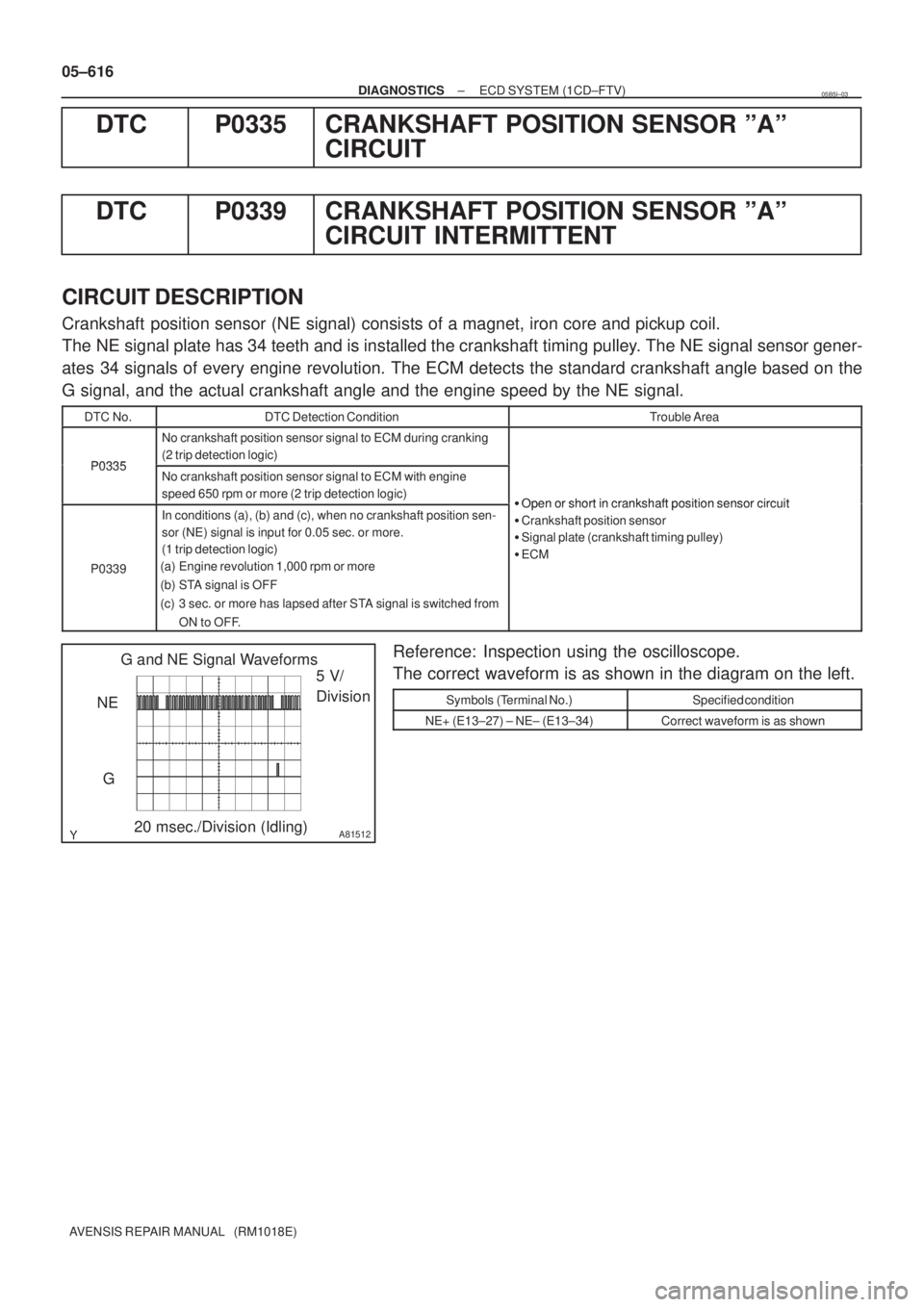
Crankshaft position sensor (NE signal) consists of a magnet, iron core and pickup coil.
The NE signal plate has 34 teeth and is installed the crankshaft timing pulley. The NE signal sensor gener-
ates 34 signals of every engine revolution. The ECM detects the standard crankshaft angle based on the
G signal, and the actual crankshaft angle and the engine speed by the NE signal.
DTC No.DTC Detection ConditionTrouble Area
P0335
No crankshaft position sensor signal to ECM during cranking
(2 trip detection logic)
P0335No crankshaft position sensor signal to ECM with engine
speed 650 rpm or more (2 trip detection logic)
�Open or short in crankshaftposition sensor circuit
P0339
In conditions (a), (b) and (c), when no crankshaft position sen-
sor (NE) signal is input for 0.05 sec. or more.
(1 trip detection logic)
(a) Engine revolution 1,000 rpm or more
(b) STA signal is OFF
(c) 3 sec. or more has lapsed after STA signal is switched from
ON to OFF.�Open or short in crankshaft position sensor circuit
�Crankshaft position sensor
�Signal plate (crankshaft timing pulley)
�ECM
Reference: Inspection using the oscilloscope.
The correct waveform is as shown in the diagram on the left.
Symbols (Terminal No.)Specified condition
NE+ (E13±27) ± NE± (E13±34)Correct waveform is as shown
05B5I±03
Page 723 of 5135
A81003
MREL B±W
GR8
3 EFI MAIN Relay
W±BE9 E13
2 IE1
EE1
EFIB±Y 1
B5
Battery FL MAINV4
VRV
VN 10
1
1
1
1A1
1
12 12 W
B±W 10GR
Engine Room R/B No. 1ECM
2
1
Engine Room
R/B No. 3 3
3 B
EC 05±612
± DIAGNOSTICSECD SYSTEM (1CD±FTV)
AVENSIS REPAIR MANUAL (RM1018E)
DTC P0234 TURBO/SUPER CHARGER OVERBOOST
CONDITION
DTC P0299 TURBO/SUPER CHARGER UNDERBOOST
DTC P1251 TURBO/SUPER CHARGER OVERBOOST
CONDITION (TOO HIGH)
CIRCUIT DESCRIPTION
DTC No.DTC Detection ConditionTrouble Area
P0234
When the condition that the turbocharger pressure exceeds the
standard value for 0.5 sec. or more. (1 trip detection logic)�VRV
�Open or short in VRV circuit
�TurbochargerP0234
P0299
P1251Actual turbocharger pressure is deviated 20 kPa (0.2 kgf/cm2,
2.9 psi) or more from the simulated target pressure based on
the engine speed and fue injection volume for 60 seconds.�Turbocharger
�Vacuum hose
�EGR valve
�ECM
WIRING DIAGRAM
05CPS±01
Page 727 of 5135

A81481
EDU Wiring DiagramCOM3
COM1 COM2
Pressure
Discharge
Valve
Injector
INJ#1
INJ#4INJ#2INJ#3
PRV
GND
EDU Connector
Control
Circuit
DC/DC
Converter
BATTERY
IJT#1
IJT#4
IJT#2
IJT#3PRDIJF
ECM
Maximum 150 V
Confirmation
Pulse Command
Pulse
Warning:
Terminal J, I, H, K, L, M, N and S are high voltage
E5
E4
Maximum 150 V
05±604
±
DIAGNOSTICS ECD SYSTEM(1CD±FTV)
AVENSIS REPAIR MANUAL (RM1018E)
DTCP0200INJECTOR CIRCUIT / OPEN
HINT:
�For more information on the EDU, see page 05±517.
�If P0200 are present, Use the diagnostic trouble code matrix for fuel sy\
stem, see page 05±517.
CIRCUIT DESCRIPTION
The EDU has been adopted to drive the injector at high speeds. The EDU has \
realized high±speed driving
under high fuel pressure conditions using the DC/DC converter that provides a\
high±voltage, quick±charging
system.
Soon after the EDU receives an injection command signal (IJT) from the\
ECM, the EDU responds to the com-
mand with injector injection confirmation signal (IJF) when the current is\
applied to the injector.
05CPR±01