Page 1219 of 5135

������������\b�����H40036
D SquibDLC3 DTC B0101/14
CG TCAirbag
Sensor
Assy
CenterSpiral
Cable
Sub±assy
C
D
E
F
������
��
��
������H41440
D Squib Airbag
Sensor
Assy
CenterSpiral
Cable
Sub±assy
Instrument Panel Wire
A
B
C
D
E
F
05±1204
±
DIAGNOSTICS SUPPLEMENTAL RESTRAINT SYSTEM
AVENSIS REPAIR MANUAL (RM1018E)
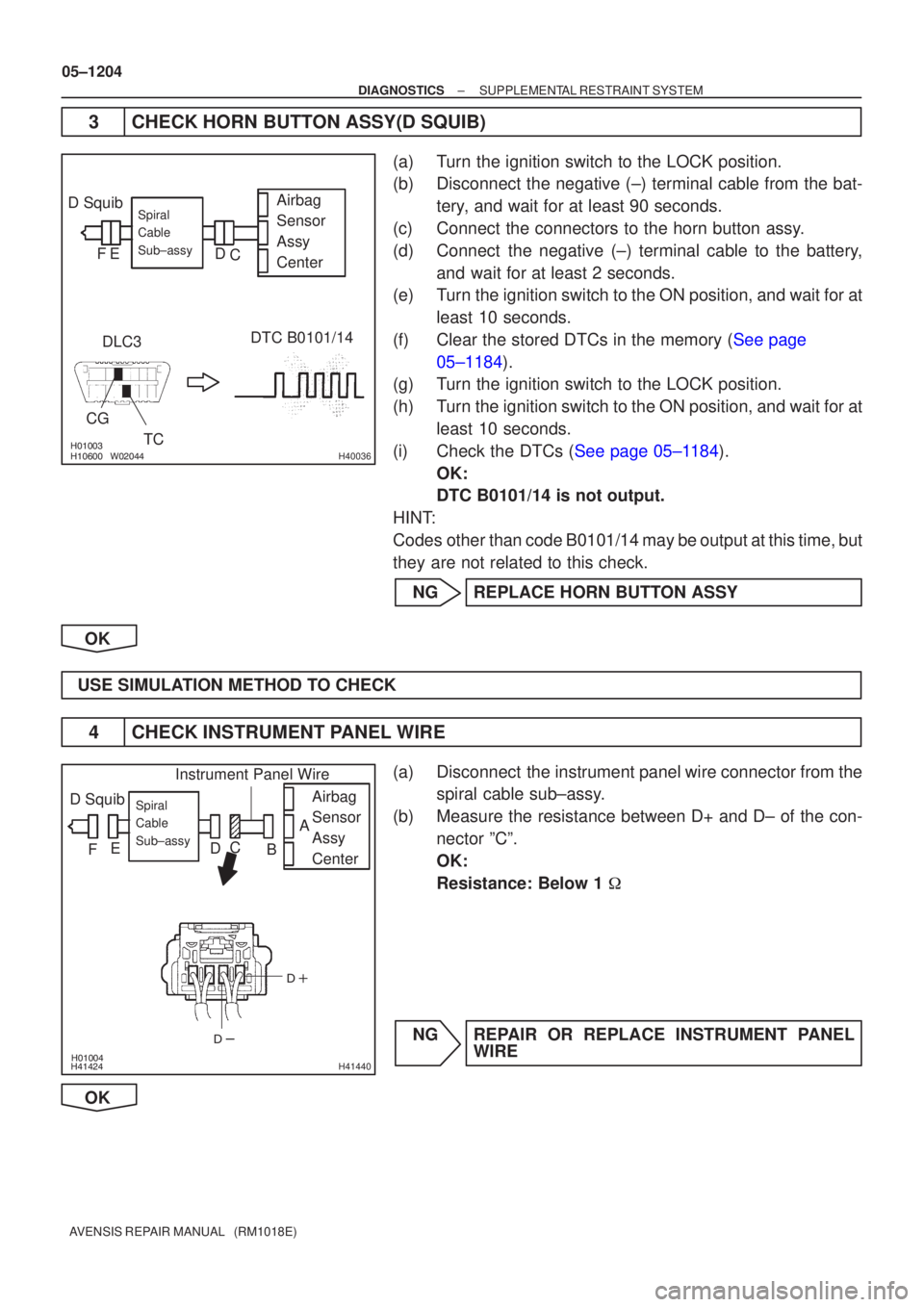
3CHECK HORN BUTTON ASSY(D SQUIB)
(a)Turn the ignition switch to the LOCK position.
(b)Disconnect the negative (±) terminal cable from the bat- tery, and wait for at least 90 seconds.
(c)Connect the connectors to the horn button assy.
(d)Connect the negative (±) terminal cable to the battery, and wait for at least 2 seconds.
(e)Turn the ignition switch to the ON position, and wait for at
least 10 seconds.
(f)Clear the stored DTCs in the memory (See page 05±1184).
(g) Turn the ignition switch to the LOCK position.
(h) Turn the ignition switch to the ON position, and wait for at
least 10 seconds.
(i)Check the DTCs (See page 05±1184). OK:
DTC B0101/14 is not output.
HINT:
Codes other than code B0101/14 may be output at this time, but
they are not related to this check.
NG REPLACE HORN BUTTON ASSY
OK
USE SIMULATION METHOD TO CHECK
4 CHECK INSTRUMENT PANEL WIRE
(a) Disconnect the instrument panel wire connector from the spiral cable sub±assy.
(b) Measure the resistance between D+ and D± of the con- nector ºCº.
OK:
Resistance: Below 1 �
NG REPAIR OR REPLACE INSTRUMENT PANEL WIRE
OK
Page 1220 of 5135
������
������H41441
D Squib Airbag
Sensor
Assy
CenterSpiral
Cable
Sub±assy
Color: Orange
A
B C
D E
F
D+ D±
± DIAGNOSTICSSUPPLEMENTAL RESTRAINT SYSTEM
05±1205
AVENSIS REPAIR MANUAL (RM1018E)
5 CHECK SPIRAL CABLE SUB±ASSY
(a) Measure the resistance between D+ and D± of the con-
nector ºEº.
OK:
Resistance: Below 1 �
NG REPLACE SPIRAL CABLE SUB±ASSY
OK
USE SIMULATION METHOD TO CHECK
Page 1221 of 5135
H01451
A30
D Squib
1
2Y±B
YA2714Airbag Sensor Assy Center
Spiral Cable
Sub±assyA2713D+
D± 05±1198
± DIAGNOSTICSSUPPLEMENTAL RESTRAINT SYSTEM
AVENSIS REPAIR MANUAL (RM1018E)
DTC B0100/13 SHORT IN D SQUIB CIRCUIT
CIRCUIT DESCRIPTION
The D squib circuit consists of the airbag sensor assy center, the spiral cable sub±assy and the horn button
assy.
This circuit actuates the SRS to deploy when the SRS deployment conditions are fulfilled.
DTC B0100/13 is recorded when a short circuit is detected in the D squib circuit.
DTC No.DTC Detecting ConditionTrouble Area
B0100/13
�Short circuit between D+ wire harness and D± wire harness
of D squib
�D squib malfunction
�Spiral cable sub±assy malfunction
�Airbag sensor assy center malfunction�Horn button assy (D squib)
�Spiral cable sub±assy
�Airbag sensor assy center
�Instrument panel wire
WIRING DIAGRAM
056LX±04
Page 1222 of 5135
������������
��
��
H41439
D Squib Airbag
Sensor
Assy
CenterSpiral
Cable
Sub±assy
Color: Orange
A
B
C
D
E
F
±
DIAGNOSTICS SUPPLEMENTAL RESTRAINT SYSTEM
05±1199
AVENSIS REPAIR MANUAL (RM1018E)
INSPECTION PROCEDURE
1CHECK CONNECTOR
(a)Turn the ignition switch to the LOCK position.
(b)Disconnect the negative (±) terminal cable from the battery, and wait for at least 90 seconds.
(c)Disconnect the connectors from the airbag sensor assy center and the hor\
n button assy.
(d)Check that the spiral cable sub±assy connectors (on the horn button \
assy side) are not damaged.
OK:
The lock button is not disengaged, or the claw of the lock is not deform\
ed or damaged.
NGREPLACE SPIRAL CABLE SUB±ASSY
OK
2CHECK D SQUIB CIRCUIT(AIRBAG SENSOR ASSY CENTER ± HORN BUTTON ASSY)
(a)Release the activation prevention mechanism built in the
connector ºBº (See page 05±1184).
(b) Measure the resistance between D+ and D± of the con-
nector ºEº.
OK:
Resistance: 1 M � or Higher
NG Go to step 5
OK
Page 1223 of 5135

������������������H40030
D SquibAirbag
Sensor
Assy
Center
DLC3
CG TC DTC B0100/13Spiral
Cable
Sub±assy
C
D
E
F
������������������H40031
D Squib Airbag
Sensor
Assy
Center
DLC3
CG TC DTC B0100/13Spiral
Cable
Sub±assy
C
D
E
F
05±1200
±
DIAGNOSTICS SUPPLEMENTAL RESTRAINT SYSTEM
AVENSIS REPAIR MANUAL (RM1018E)
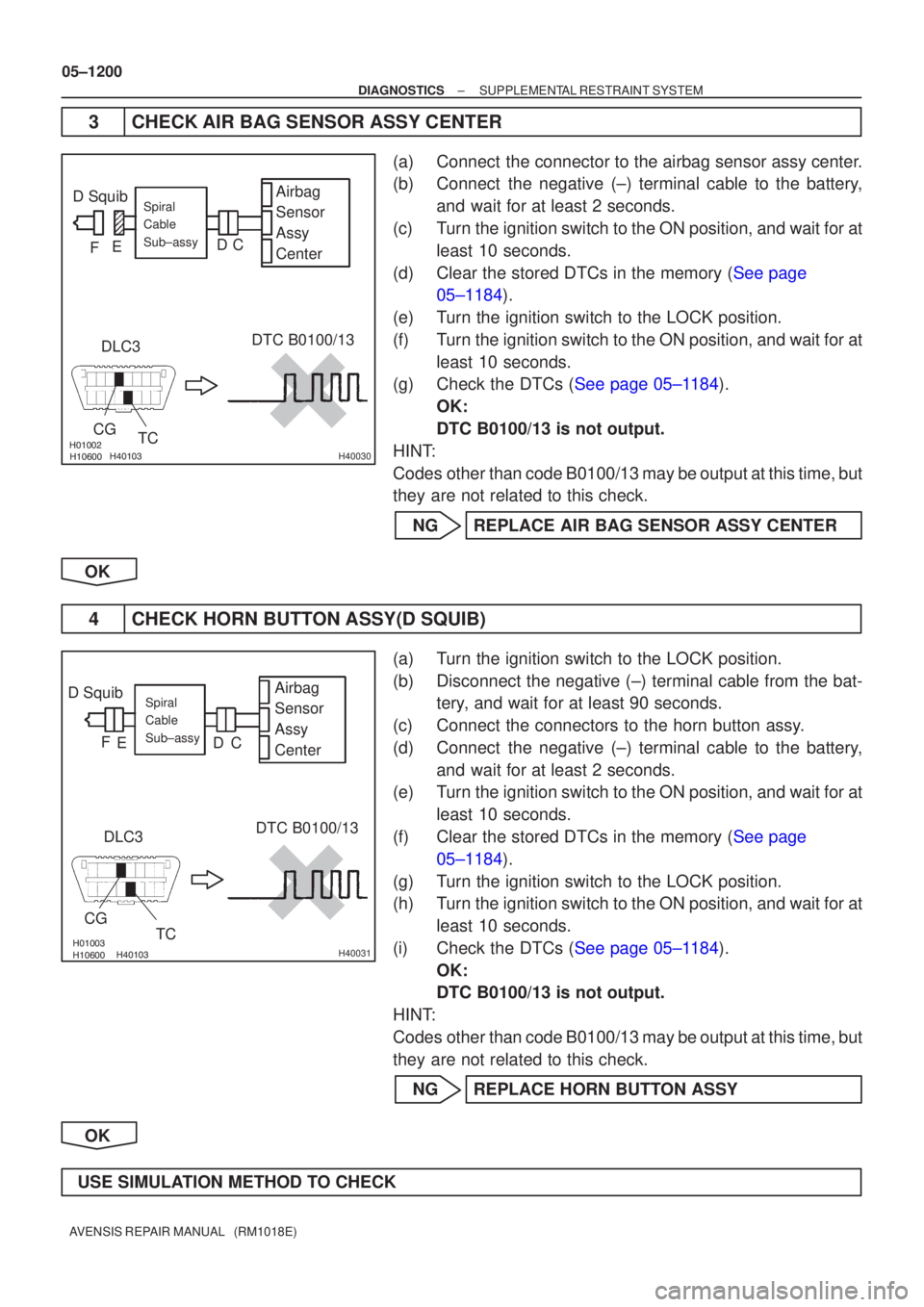
3CHECK AIR BAG SENSOR ASSY CENTER
(a)Connect the connector to the airbag sensor assy center.
(b)Connect the negative (±) terminal cable to the battery, and wait for at least 2 seconds.
(c)Turn the ignition switch to the ON position, and wait for at least 10 seconds.
(d)Clear the stored DTCs in the memory (See page 05±1184).
(e)Turn the ignition switch to the LOCK position.
(f)Turn the ignition switch to the ON position, and wait for at least 10 seconds.
(g)Check the DTCs (See page 05±1184).
OK:
DTC B0100/13 is not output.
HINT:
Codes other than code B0100/13 may be output at this time, but
they are not related to this check.
NGREPLACE AIR BAG SENSOR ASSY CENTER
OK
4CHECK HORN BUTTON ASSY(D SQUIB)
(a)Turn the ignition switch to the LOCK position.
(b)Disconnect the negative (±) terminal cable from the bat- tery, and wait for at least 90 seconds.
(c)Connect the connectors to the horn button assy.
(d)Connect the negative (±) terminal cable to the battery, and wait for at least 2 seconds.
(e)Turn the ignition switch to the ON position, and wait for at
least 10 seconds.
(f)Clear the stored DTCs in the memory (See page 05±1184).
(g) Turn the ignition switch to the LOCK position.
(h) Turn the ignition switch to the ON position, and wait for at least 10 seconds.
(i)Check the DTCs (See page 05±1184). OK:
DTC B0100/13 is not output.
HINT:
Codes other than code B0100/13 may be output at this time, but
they are not related to this check.
NG REPLACE HORN BUTTON ASSY
OK
USE SIMULATION METHOD TO CHECK
Page 1224 of 5135
\b�����
��
��
\b�����H41440
D Squib Airbag
Sensor
Assy
CenterSpiral
Cable
Sub±assy
Instrument Panel Wire
A
B
C
D
E
F
\b�����
������H41441
D Squib Airbag
Sensor
Assy
CenterSpiral
Cable
Sub±assy
Color: Orange
A
B
C
D
E
F
D± D+
±
DIAGNOSTICS SUPPLEMENTAL RESTRAINT SYSTEM
05±1201
AVENSIS REPAIR MANUAL (RM1018E)
5CHECK INSTRUMENT PANEL WIRE
(a)Disconnect the instrument panel wire connector from the
spiral cable sub±assy.
(b)Release the activation prevention mechanism built in the connector of the connector ºBº (See page
05±1184).
(c)Measure the resistance between D+ and D± of the con- nector ºCº.
OK:
Resistance: 1 M � or Higher
NGREPAIR OR REPLACE INSTRUMENT PANEL WIRE
OK
6CHECK SPIRAL CABLE SUB±ASSY
(a)Release the activation prevention mechanism built in the connector ºDº (See page 05±1184).
(b) Measure the resistance between D+ and D± of the con-
nector ºEº.
OK:
Resistance: 1 M � or Higher
NG REPLACE SPIRAL CABLE SUB±ASSY
OK
USE SIMULATION METHOD TO CHECK
Page 1226 of 5135

05C5W±01
H40533
A26A27
A28
± DIAGNOSTICSSUPPLEMENTAL RESTRAINT SYSTEM
05±1195
AVENSIS REPAIR MANUAL (RM1018E)
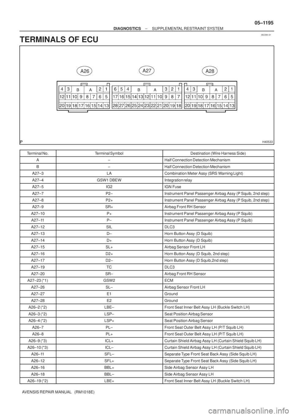
TERMINALS OF ECU
Terminal No.Terminal SymbolDestination (Wire Harness Side)
A±Half Connection Detection Mechanism
B±Half Connection Detection Mechanism
A27±3LACombination Meter Assy (SRS Warning Light)
A27±4GSW1 DBEWIntegration relay
A27±5IG2IGN Fuse
A27±7P2±Instrument Panel Passenger Airbag Assy (P Squib, 2nd step)
A27±8P2+Instrument Panel Passenger Airbag Assy (P Squib, 2nd step)
A27±9SR+Airbag Front RH Sensor
A27±10P+Instrument Panel Passenger Airbag Assy (P Squib)
A27±11P±Instrument Panel Passenger Airbag Assy (P Squib)
A27±12SILDLC3
A27±13D±Horn Button Assy (D Squib)
A27±14D+Horn Button Assy (D Squib)
A27±15SL+Airbag Sensor Front LH
A27±16D2+Horn Button Assy (D Squib, 2nd step)
A27±17D2±Horn Button Assy (D Squib,2nd step)
A27±19TCDLC3
A27±20SR±Airbag Front RH Sensor
A27±23 (*1)GSW2ECM
A27±26SL±Airbag Sensor Front LH
A27±27E1Ground
A27±28E2Ground
A26±2 (*2)LBE±Front Seat Inner Belt Assy LH (Buckle Switch LH)
A26±3 (*2)LSP±Seat Position Airbag Sensor
A26±4 (*2)LSP+Seat Position Airbag Sensor
A26±7PL±Front Seat Outer Belt Assy LH (P/T Squib LH)
A26±8PL+Front Seat Outer Belt Assy LH (P/T Squib LH)
A26±9 (*3)ICL+Curtain Shield Airbag Assy LH (Curtain Shield Squib LH)
A26±10 (*3)ICL±Curtain Shield Airbag Assy LH (Curtain Shield Squib LH)
A26±11SFL±Separate Type Front Seat Back Assy (Side Squib LH)
A26±12SFL+Separate Type Front Seat Back Assy (Side Squib LH)
A26±16BBL+Side Airbag Sensor Assy LH
A26±18BBL±Side Airbag Sensor Assy LH
A26±19 (*2)LBE+Front Seat Inner Belt Assy LH (Buckle Switch LH)
Page 1227 of 5135
05±1196
± DIAGNOSTICSSUPPLEMENTAL RESTRAINT SYSTEM
AVENSIS REPAIR MANUAL (RM1018E)Terminal No.Destination (Wire Harness Side) Terminal Symbol
A28±1 (*4)RSP+Seat Position Airbag Sensor
A28±2 (*4)RSP±Seat Position Airbag Sensor
A28±3 (*4)RBE±Front Seat Inner Belt Assy RH (Buckle Switch RH)
A28±5SFR+Separate Type Front Seat Back Assy (Side Squib RH)
A28±6SFR±Separate Type Front Seat Back Assy (Side Squib RH)
A28±7 (*3)ICR±Curtain Shield Airbag Assy RH (Curtain Shield Squib RH)
A28±8 (*3)ICR+Curtain Shield Airbag Assy RH(Curtain Shield Squib RH)
A28±9PR+Front Seat Outer Belt Assy RH (P/T Squib RH)
A28±10PR±Front Seat Outer Belt Assy RH (P/T Squib RH)
A28±11DK±Instrument Panel Airbag Assy (Knee Squib)
A28±12DK+Instrument Panel Airbag Assy (Knee Squib)
A28±14 (*4)RBE+Front Seat Inner Belt Assy RH (Buckle Switch RH)
A28±15BBR±Side Airbag Sensor Assy RH
A28±17BBR+Side Airbag Sensor Assy RH
*1: Gasoline Engine
*2: LHD
*3: w/ Curtain Shield Airbag
*4: RHD