Page 89 of 5135

SUPPLEMENTAL RESTRAINT SYSTEM
PREPARATION
SST
09082±00700SRS Airbag Deployment ToolHORN BUTTON ASSY
CURT")
022L5±01
02±52
± PREPARATIONSUPPLEMENTAL RESTRAINT SYSTEM
AVENSIS REPAIR MANUAL (RM1018E)
SUPPLEMENTAL RESTRAINT SYSTEM
PREPARATION
SST
09082±00700SRS Airbag Deployment ToolHORN BUTTON ASSY
CURTAIN SHIELD AIR BAG ASSY LH
FRONT SEAT AIRBAG ASSY LH
INSTRUMENT PANEL PASSENGER
AIR BAG ASSY
INSTRUMENT PANEL AIR BAG
ASSY
09082±00750Airbag Deployment Wire
Sub±harness No.3FRONT SEAT AIRBAG ASSY LH
09082±00780Airbag Deployment Wire
Sub±harness No.6HORN BUTTON ASSY
INSTRUMENT PANEL PASSENGER
AIR BAG ASSY
09082±00802Airbag Deployment Wire
Sub±Harness No. 8HORN BUTTON ASSY
CURTAIN SHIELD AIR BAG ASSY LH
INSTRUMENT PANEL AIR BAG
ASSY
(09082±10801)Wire AHORN BUTTON ASSY
CURTAIN SHIELD AIR BAG ASSY LH
INSTRUMENT PANEL AIR BAG
ASSY
(09082±20801)Wire BCURTAIN SHIELD AIR BAG ASSY LH
INSTRUMENT PANEL AIR BAG
ASSY
(09082±30801)Wire CHORN BUTTON ASSY
09950±50013Puller C SetSPIRAL CABLE SUB±ASSY
(09951±05010)Hanger 150SPIRAL CABLE SUB±ASSY
(09952±05010)Slide ArmSPIRAL CABLE SUB±ASSY
(09953±05020)Center Bolt 150SPIRAL CABLE SUB±ASSY
(09954±05021)Claw No.2SPIRAL CABLE SUB±ASSY
Page 90 of 5135
± PREPARATIONSUPPLEMENTAL RESTRAINT SYSTEM
02±53
AVENSIS REPAIR MANUAL (RM1018E)
Recomended Tools
09042±00010Torx Socket T30HORN BUTTON ASSY
SPIRAL CABLE SUB±ASSY
09070±20010Moulding RemoverAIR BAG SENSOR ASSY CENTER
Equipment
Torque wrench
Bolt Length: 35.0 mm (1.378 in.) Pitch: 1.0 mm (0.039 in.)
Diam.: 6.0 mm (0.236 in.)Airbag disposal
Tire Width: 185 mm (7.28 in.) Inner diam.: 360 mm (14.17 in.)Airbag disposal
Tire with disc wheel Width: 185 mm (7.28 in.)
Inner diam.: 360 mm (14.17 in.)Airbag disposal
Plastic bagAirbag disposal
Page 159 of 5135

SEAT
TORQUE SPECIFICATION
Part TightenedN�mkgf�cmft�lbf
FRONT SEAT
Seat Inner belt assy x Seat adjuster assy4242831
Sea")
031HN±01
± SERVICE SPECIFICATIONSSEAT
03±71
AVENSIS REPAIR MANUAL (RM1018E)
SEAT
TORQUE SPECIFICATION
Part TightenedN�mkgf�cmft�lbf
FRONT SEAT
Seat Inner belt assy x Seat adjuster assy4242831
Seatback cover bracket x Seat adjuster assy (w/ Side airbag)6.06153 in.�lbf
Seat assy x Body3737527
Seat position airbag sensor x Seat adjuster assy8.08271 in.�lbf
Power seat motor assy (Reclining) x Seat adjuster assy4.54640 in.�lbf
Power seat motor assy (Slide) x Seat adjuster assy Bolt
Nut4.0
3.541
3635 in.�lbf
31 in.�lbf
Power seat motor assy (lifter) x Seat adjuster assy Bolt
Nut2.5
2525
25522 in.�lbf
18
Power seat motor assy (Front vertical) x Seat adjuster assy Bolt
Nut2.5
2525
25522 in.�lbf
18
Front seatback spring assy x Front seat adjuster2525518
REAR SEAT
Armrest assy x Seatback assy8.08271 in.�lbf
Seat belt assy outer center x Seatback frame4242831
Seat belt assy outer center x Body4242831
Seatback lock assy x Seatback frame3030622
Seatback hinge x Seatback frame1818513
Seatback hinge x Body1818513
Seatback hinge center x Body1818513
Seatback hinge center x Seatback frame1818513
Side seatback assy x Body1818513
Bench type seatback assy x Body1818513
Seat cushion frame x Body1818513
Page 160 of 5135
031I3±01
03±70
± SERVICE SPECIFICATIONSINSTRUMENT PANEL/METER
AVENSIS REPAIR MANUAL (RM1018E)
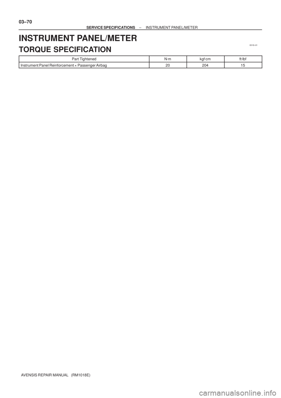
INSTRUMENT PANEL/METER
TORQUE SPECIFICATION
Part TightenedN�mkgf�cmft�lbf
Instrument Panel Reinforcement �Passenger Airbag2020415
Page 167 of 5135
031HM±01
± SERVICE SPECIFICATIONSSUPPLEMENTAL RESTRAINT SYSTEM
03±63
AVENSIS REPAIR MANUAL (RM1018E)
SUPPLEMENTAL RESTRAINT SYSTEM
TORQUE SPECIFICATION
Part TightenedN�mkgf�cmft�lbf
Horn button assy x Steering wheel assy8.89078 in.�lbf
Steering wheel assy x Steering column assy5051037
Instrument panel passenger airbag assy x Instrument panel reinforcement2020014
Curtain shield airbag assy x Body3.53631 in.�lbfCurtain shield airbag assy x Body3.5
14
36
143
31 in.lbf
10
Instrument panel airbag assy x Instrument panel reinforcement1818413
Airbag sensor assy center x Body17.517813
Airbag front sensor set bolt7.57666 in.�lbf
Side airbag sensor assy LH x Body17.517813
Airbag sensor rear LH x Body17.517813
Seat position airbag sensor x Front seat8.08271 in.�lbf
Page 172 of 5135

TORQUE SPECIFICATION
Part TightenedN�mkgf�cmft�lbf
Steering intermediate shaft assy No. 2 x Oil pressure pow")
031FZ±01
03±58
± SERVICE SPECIFICATIONSSTEERING COLUMN
AVENSIS REPAIR MANUAL (RM1018E)
TORQUE SPECIFICATION
Part TightenedN�mkgf�cmft�lbf
Steering intermediate shaft assy No. 2 x Oil pressure power steering
column assy (LHD steering positoin type)2828621
Steering sliding yoke sub±assy x Oil pressure power steering column assy
(RHD steering positoin type)2828621
Steering intermediate shaft assy No. 2 x Electric power steering column
assy (LHD steering positoin type)3536026
Steering sliding yoke sub±assy x Electric power steering column assy
(RHD steering positoin type)3536026
Steering sliding yoke sub±assy x Steering intermediate shaft assy No. 23536026
Steering column assy set bolt2121415
Steering sliding yoke sub±assy x Steering gear assy
(LHD steering positoin type)3536026
Steering intermediate shaft assy No. 2 x Steering gear assy
(RHD steering positoin type)3536026
Steering wheel set nut5051037
Steering wheel pad set screw (Torx screw)8.89078 in.´lbf
Steering column cover LWR x Steering column assy5.05144 in.´lbf
Instrument panel airbag assy1818413
Power steering ECU assy (Bolt A)88271 in.´lbf
Power steering ECU assy (Bolt B)15.515811
Page 1217 of 5135

DTCB0")
������������
��
��
H41439
D SquibAirbag
Sensor
Assy
CenterSpiral
Cable
Sub±assy
Color: Orange
A
B
C
D
E
F
05±1202
±
DIAGNOSTICS SUPPLEMENTAL RESTRAINT SYSTEM
AVENSIS REPAIR MANUAL (RM1018E)
DTCB0101/14OPEN IN D SQUIB CIRCUIT
CIRCUIT DESCRIPTION
The D squib circuit consists of the airbag sensor assy center, the spiral cable sub±assy and the horn button
assy.
This circuit actuates the SRS to deploy when the SRS deployment conditions a\
re fulfilled.
DTC B0101/14 is recorded when an open circuit is detected in the D squib\
circuit.
DTC No.DTC Detecting ConditionTrouble Area
B0101/14
� Open circuit in D+ wire harness or D± wire harness of D
squib
� D squib malfunction
� Spiral cable sub±assy malfunction
� Airbag sensor assy center malfunction�Horn button assy (D squib)
� Spiral cable sub±assy
� Airbag sensor assy center
� Instrument panel wire
WIRING DIAGRAM
See page 05±1198.
INSPECTION PROCEDURE
1 CHECK D SQUIB CIRCUIT(AIRBAG SENSOR ASSY CENTER ± HORN BUTTON
ASSY)
(a) Turn the ignition switch to the LOCK position.
(b) Disconnect the negative (±) terminal cable from the bat-
tery, and wait for at least 90 seconds.
(c) Disconnect the connectors from the airbag sensor assy
center and the horn button assy.
(d) Measure the resistance between D+ and D± of the con- nector ºEº.
OK:
Resistance: Below 1 �
NG Go to step 4
OK
056LY±04
Page 1218 of 5135

�����
����� \b����������H42104
D SquibAirbag
Sensor
Assy
Center
D±D+Spiral
Cable
Sub±assy
Color: Orange
TC
CG
DLC3 DTC B0101/14
Service Wire
C
D
E
F
±
DIAGNOSTICS SUPPLEMENTAL RESTRAINT SYSTEM
05±1203
AVENSIS REPAIR MANUAL (RM1018E)
2CHECK AIR BAG SENSOR ASSY CENTER
(a)Connect the connector to the airbag sensor assy center.
(b)Using a service wire, connect D+ and D± of the connector
ºEº.
NOTICE:
Do not forcibly insert a service wire into the terminal of the
connector when connecting.
(c)Connect the negative (±) terminal cable to the battery, and wait for at least 2 seconds.
(d)Turn the ignition switch to the ON position, and wait for at least 10 seconds.
(e)Clear the stored DTCs in the memory (See page
05±1184).
(f) Turn the ignition switch to the LOCK position.
(g) Turn the ignition switch to the ON position, and wait for at least 10 seconds.
(h)Check the DTCs (See page 05±1184).
OK:
DTC B0101/14 is not output.
HINT:
Codes other than code B0101/14 may be output at this time, but
they are not related to this check.
NG REPLACE AIR BAG SENSOR ASSY CENTER
OK

Recomended Tools
09042±00010Torx Socket T30HORN BUTTON ASSY
SPIRAL CABLE SUB±ASSY
09070±20010Moulding RemoverAIR")