Page 1213 of 5135
������
I36744
Driver Side J/BA/C Control Assembly
1
DN6
DC AM1
HTR1
DH
5
DH9
DAW±BR±W
(*3)R±W
(*4)J26 J26R±W
(*4) HHJ/C
1
CB2
CER±W
(*3)A1612
IG
I13 Ignition SW
G±Y G±R
IG1 AM1 13Center J/B
6
CA3
CGW±B
(*3)A1613
GND Center J/B
B±G
(*1)53
12
1
4D
1 2 120A ALT (*5)
1
4B
3
1 2 140A ALT
3 B±L
(*2)ED11
W
(*2)
B
(*2)
B±G
(*1)
FL MAIN
Battery
IJ IP IK *1: Gasoline
*2: 1CD±FTV
*3: LHD
*4: RHD
*5: 1AZ±FSE, 1AZ±FE
*6: 1ZZ±FE, 3ZZ±FEW±B
(*4)
A
J15
J/C W±B
(*3) IG1 Relay
Engine Room R/B No.4
Engine Room R/B No.3100A ALT (*6)
W±B
(*4)J17
J/C
AA 05±1144
± DIAGNOSTICSAIR CONDITIONING SYSTEM
AVENSIS REPAIR MANUAL (RM1018E)
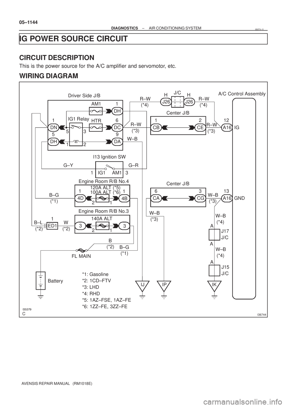
IG POWER SOURCE CIRCUIT
CIRCUIT DESCRIPTION
This is the power source for the A/C amplifier and servomotor, etc.
WIRING DIAGRAM
050TV±11
Page 1215 of 5135
I35395
Fuse Block Center J/BA/C Control Assembly
ECU±B2
66
12CC CF 10 7
W±R W±R
A1624
+B
B±W
IE4 IP145
(*3) (*4)B±W Engine Room R/B No.1 & Engine Room J/B No.1B±G (*1)
B (*2) DCC
11A
1 21
Engine Room R/B No.3
Engine Room J/B No.4
Center J/B B (*2)
B±G (*1)B (*2)
B±G (*1) 33
4A 4B
CG CA W±B (*3) W±B (*3)11
63
A1613
GND
FL MAIN
Battery
IP IKAAA W±B (*4) W±B (*4)J17
J/C
*1: Gasoline
*2: 1CD±FTV*3: LHD
*4: RHDJ15
J/C 05±1142
± DIAGNOSTICSAIR CONDITIONING SYSTEM
AVENSIS REPAIR MANUAL (RM1018E)
BACK±UP POWER SOURCE CIRCUIT
CIRCUIT DESCRIPTION
This is the back±up power source for the A/C amplifier. Power is supplied even when the ignition switch is
off and is used for diagnostic trouble code memory etc.
WIRING DIAGRAM
050TW±10
Page 1217 of 5135

DTCB0")
������������
��
��
H41439
D SquibAirbag
Sensor
Assy
CenterSpiral
Cable
Sub±assy
Color: Orange
A
B
C
D
E
F
05±1202
±
DIAGNOSTICS SUPPLEMENTAL RESTRAINT SYSTEM
AVENSIS REPAIR MANUAL (RM1018E)
DTCB0101/14OPEN IN D SQUIB CIRCUIT
CIRCUIT DESCRIPTION
The D squib circuit consists of the airbag sensor assy center, the spiral cable sub±assy and the horn button
assy.
This circuit actuates the SRS to deploy when the SRS deployment conditions a\
re fulfilled.
DTC B0101/14 is recorded when an open circuit is detected in the D squib\
circuit.
DTC No.DTC Detecting ConditionTrouble Area
B0101/14
� Open circuit in D+ wire harness or D± wire harness of D
squib
� D squib malfunction
� Spiral cable sub±assy malfunction
� Airbag sensor assy center malfunction�Horn button assy (D squib)
� Spiral cable sub±assy
� Airbag sensor assy center
� Instrument panel wire
WIRING DIAGRAM
See page 05±1198.
INSPECTION PROCEDURE
1 CHECK D SQUIB CIRCUIT(AIRBAG SENSOR ASSY CENTER ± HORN BUTTON
ASSY)
(a) Turn the ignition switch to the LOCK position.
(b) Disconnect the negative (±) terminal cable from the bat-
tery, and wait for at least 90 seconds.
(c) Disconnect the connectors from the airbag sensor assy
center and the horn button assy.
(d) Measure the resistance between D+ and D± of the con- nector ºEº.
OK:
Resistance: Below 1 �
NG Go to step 4
OK
056LY±04
Page 1221 of 5135
H01451
A30
D Squib
1
2Y±B
YA2714Airbag Sensor Assy Center
Spiral Cable
Sub±assyA2713D+
D± 05±1198
± DIAGNOSTICSSUPPLEMENTAL RESTRAINT SYSTEM
AVENSIS REPAIR MANUAL (RM1018E)
DTC B0100/13 SHORT IN D SQUIB CIRCUIT
CIRCUIT DESCRIPTION
The D squib circuit consists of the airbag sensor assy center, the spiral cable sub±assy and the horn button
assy.
This circuit actuates the SRS to deploy when the SRS deployment conditions are fulfilled.
DTC B0100/13 is recorded when a short circuit is detected in the D squib circuit.
DTC No.DTC Detecting ConditionTrouble Area
B0100/13
�Short circuit between D+ wire harness and D± wire harness
of D squib
�D squib malfunction
�Spiral cable sub±assy malfunction
�Airbag sensor assy center malfunction�Horn button assy (D squib)
�Spiral cable sub±assy
�Airbag sensor assy center
�Instrument panel wire
WIRING DIAGRAM
056LX±04
Page 1242 of 5135
������I35971
A11
AlternatorPower Heater ECU
L EE1
P1ALT+L A114
38
YY
± DIAGNOSTICSCOMBUSTION TYPE POWER HEATER SYSTEM
05±1179
AVENSIS REPAIR MANUAL (RM1018E)
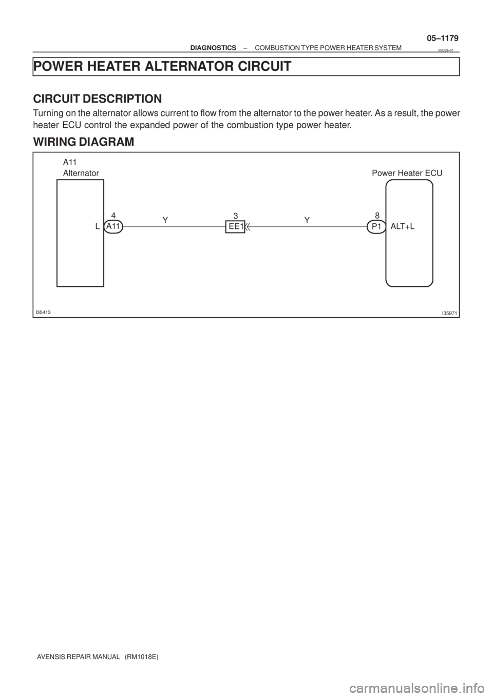
POWER HEATER ALTERNATOR CIRCUIT
CIRCUIT DESCRIPTION
Turning on the alternator allows current to flow from the alternator to the power heater. As a result, the power
heater ECU control the expanded power of the combustion type power heater.
WIRING DIAGRAM
05C83±01
Page 1244 of 5135
I35412
F17
Fuel Pump
M
21L
W±B
ECP12
F/P Power Heater ECU 05±1176
± DIAGNOSTICSCOMBUSTION TYPE POWER HEATER SYSTEM
AVENSIS REPAIR MANUAL (RM1018E)
POWER HEATER FUEL PUMP CIRCUIT
CIRCUIT DESCRIPTION
When the power heater switch is turned on, the fuel pump receives the drive voltage from the power heater
ECU, causing the combustion type power heater to operate.
WIRING DIAGRAM
05C82±01
Page 1247 of 5135
I36132
Center J/BP5
Power Heater SWPower Heater ECU
CB1
CK12
R±W G±Y G±Y
IE612
P13
SW
W±B
R±W36IG IN
2 E
Driver Side J/B
B±L
DN
DH5 1 IG1 Relay HTR
DC
DA9 6
DH1W±B
AM1
I13
Ignition SW
1 IG1 AM1 3G±R
Engine Room R/B No.3
ALT
ED11
B±L W
33
21
B
FL MAIN
Battery
IJ IKA
J15
J/C 53
12
G±Y
± DIAGNOSTICSCOMBUSTION TYPE POWER HEATER SYSTEM
05±1173
AVENSIS REPAIR MANUAL (RM1018E)
POWER HEATER SWITCH CIRCUIT
CIRCUIT DESCRIPTION
When the power heter switch is turned on, the power heater ECU sends the drive signal to the fuel pump,
causing the combustion type power heater to operate.
WIRING DIAGRAM
05C81±01
Page 1250 of 5135
H01454
S18
Side Squib LHAirbag Sensor Assy Center
SFL+
SFL± Y±R
Y±G 1
211 12
A26
A26 05±1238
± DIAGNOSTICSSUPPLEMENTAL RESTRAINT SYSTEM
AVENSIS REPAIR MANUAL (RM1018E)
DTC B0115/47 SHORT IN SIDE SQUIB (LH) CIRCUIT
CIRCUIT DESCRIPTION
The side squib LH circuit consists of the airbag sensor assy center and the separate type front seat back
assy (side squib LH).
This circuit actuates the SRS to deploy when the SRS deployment conditions are fulfilled.
DTC B0115/47 is recorded when a short circuit is detected in the side squib LH circuit.
DTC No.DTC Detecting ConditionTrouble Area
B0115/47
�Short circuit between SFL+ wire harness and SFL± wire har-
ness of side squib LH
�Side squib LH malfunction
�Airbag sensor assy center malfunction�Separate type front seat back assy (Side squib LH)
�Airbag sensor assy center
�Floor wire
WIRING DIAGRAM
056M3±03
 (*4)B±W Engine Room R/B No.1 & Engine Room J/B No.1B±G (*1)
B (*2) DCC
11A
1 21
Engine")

DTC B0100/13 SHORT I")

POWER HEATER FUEL PUMP CIRCUIT
CIRCUIT DESCRIPTI")


DTC B0115/47 SHORT IN SID")