Page 1108 of 5135
G25416
ECM
KD *
112
E10 K2
Kick Down SW
IP6
CA
12 CJ
W±BCenter J/B
6
IG1 IG112
W WW±B W±B
*1: LHD
± DIAGNOSTICSELECTRONIC CONTROLLED AUTOMATIC
TRANSAXLE [ECT] (U341E)05±1033
AVENSIS REPAIR MANUAL (RM1018E)
KICK DOWN SWITCH CIRCUIT
CIRCUIT DESCRIPTION
The kick±down switch is turned ON when the accelerator pedal is depressed to the full throttle and sends
signals to ECM.
When the kick±down switch is turned ON, the ECM controls gear shifting according to the programmed shift
diagrams.
If a short circuit develops in the kick±down switch, the ECM disregards the kick±down signals and controls
shifting at the normal shift points.
WIRING DIAGRAM
05C8O±01
Page 1118 of 5135
F44863
D5
DLC3Power Steering
ECU Assy
J/C
TS
CG12
4J8D (*1)
J16
J/CA J20D (*2)
J20D
(*2)J9B
(*1)W (*1) W
Center J/B
CB3
CA6E1511
IO IP *1: LHD
*2 RHD TS
W (*2)
W±B (*2)
W±B (*1)
A W±B (*2)
W±B (*1) 05±1086
± DIAGNOSTICSELECTRONIC MOTOR POWER STEERING SYSTEM
AVENSIS REPAIR MANUAL (RM1018E)
TS TERMINAL CIRCUIT
CIRCUIT DESCRIPTION
After making short circuit between terminal Ts and CG of DLC3 with turning the ignition switch OFF, the mode
will change from the normal mode to test mode when the ignition switch is turned ON. After the ignition switch
is turned ON, there will be DTC output from Tc terminal of DLC3.
WIRING DIAGRAM
050XA±04
Page 1120 of 5135
F44864
D5
DLC3Power Steering
ECU Assy
TC13 W±L W±L
J8 J21 J9 J20
(*1) (*2) (*1) (*2)J/C
E15 TC4 B D D B
CG4 W±B (*2) W±B (*2)
CBCenter J/B
3
CA6
W±B (*1)
IO IPA
A J16
J/C
W±B (*1)
*1: LHD
*2: RHD 05±1084
± DIAGNOSTICSELECTRONIC MOTOR POWER STEERING SYSTEM
AVENSIS REPAIR MANUAL (RM1018E)
TC TERMINAL CIRCUIT
CIRCUIT DESCRIPTION
When the terminals Tc and CG of DLC3 are connected, the power steering ECU assy displays the DTC.
WIRING DIAGRAM
050X7±04
Page 1122 of 5135
F44861
B±W22
C11Combination Meter
Driver Side J/B
Engine Room R/B No.4 Engine Room R/B No.1 and
Engine Room J/B No.1Power Steering
ECU Assy
6
C11
17
C10B±W
W±B
W±B
B±WP/S
J8C
AM2 J26A
J8C
J26A J/C
B±WB±R
B±R B±R B±R
B±RB±GB±G
B±G (*1) (*2) (*1) (*2)(*1)
(*2)
18
DA2
DH IGN
IE41
IP11
(*1) (*2)
1
1A1
111
4A
4B
2AM2 IG2 I13
Ignition SWE159
WL
46
FL MAIN
BatteryJ15
J/CJ16
J/C
IK
IO AA
*1: LHD
*2: RHDA
AJ17
J/C
A W±B
(*2)
W±B
(*1) 05±1082
± DIAGNOSTICSELECTRONIC MOTOR POWER STEERING SYSTEM
AVENSIS REPAIR MANUAL (RM1018E)
EMPS Warning Light Circuit
CIRCUIT DESCRIPTION
If the power steering ECU assy detects a trouble, the PS warning lights up. At this time, the power steering
ECU assy records a DTC in memory.
WIRING DIAGRAM
05C5I±01
Page 1124 of 5135
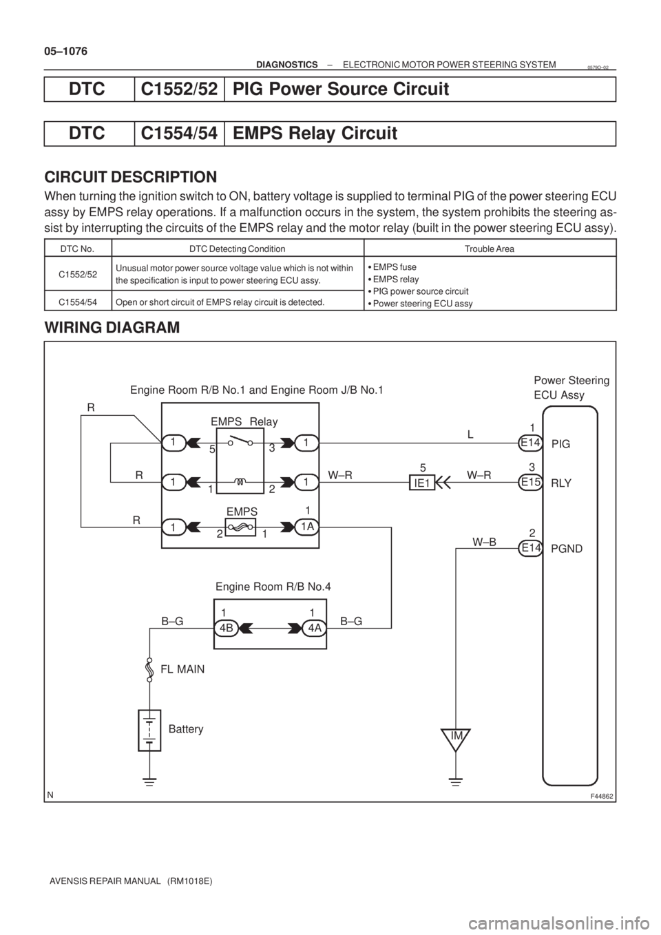
F44862
Engine Room R/B No.1 and
Engine Room J/B No.1Power Steering
ECU Assy
Engine Room R/B No.4 EMPS Relay
W±R
FL MAIN
BatteryPIG
RLY
PGND R
R
RIE1L
1 1 11
1
1A
1 22 1
1
EMPS 53
51
E14
3
E15
2
E14 W±R
W±B
B±G
4B1
4A1
IM B±G 05±1080
± DIAGNOSTICSELECTRONIC MOTOR POWER STEERING SYSTEM
AVENSIS REPAIR MANUAL (RM1018E)
DTC C1555/55 EMPS Motor Relay Circuit
CIRCUIT DESCRIPTION
If a malfunction occurs in the system, the system prohibits the steering assist by interrupting the circuits of
the EMPS relay and the motor relay (built in the power steering ECU assy).
DTC No.DTC Detecting ConditionTrouble Area
C1555/55Open or short circuit of EMPS motor relay in the ECU circuit is
detected.Power steering ECU assy
WIRING DIAGRAM
0579Q±02
Page 1126 of 5135

F44862
Engine Room R/B No.1 and Engine Room J/B No.1Power Steering
ECU Assy
Engine Room R/B No.4 EMPS Relay
W±R
FL MAIN
BatteryPIG
RLY
PGND R
R
RIE1L
1 1 1
1
1
1A
1 22 1
1
EMPS 53
51
E14
3
E15
2
E14 W±R
W±B
B±G
4B1
4A1
IM B±G 05±1076
± DIAGNOSTICSELECTRONIC MOTOR POWER STEERING SYSTEM
AVENSIS REPAIR MANUAL (RM1018E)
DTC C1552/52 PIG Power Source Circuit
DTC C1554/54 EMPS Relay Circuit
CIRCUIT DESCRIPTION
When turning the ignition switch to ON, battery voltage is supplied to terminal PIG of the power steering ECU
assy by EMPS relay operations. If a malfunction occurs in the system, the system prohibits the steering as-
sist by interrupting the circuits of the EMPS relay and the motor relay (built in the power steering ECU assy).
DTC No.DTC Detecting ConditionTrouble Area
C1552/52Unusual motor power source voltage value which is not within
the specification is input to power steering ECU assy.�EMPS fuse
�EMPS relay
�PIG power source circuitC1554/54Open or short circuit of EMPS relay circuit is detected.�PIG power source circuit
�Power steering ECU assy
WIRING DIAGRAM
0579O±02
Page 1130 of 5135
F44867
Engine Room R/B No. 4 I13
Ignition SWDriver Side J/B
ECU±IG
AM1
ALT
FL MAIN
BatteryIG1Relay
AM1 IG1IG
PGND R±W
R±WR±W
W±B
W±B
W±B B±G B±GG±Y
G±RJ10G
J20C
J11G
J21C
E156
E142 DB 18
DH5
DH1
DN1 DA9
4B1
4D1
IJ IM 12125 3
31J/C
(*1)
(*2)(*1)
(*2)
*1: LHD
*2: RHDPower Steering
ECU Assy
± DIAGNOSTICSELECTRONIC MOTOR POWER STEERING SYSTEM
05±1073
AVENSIS REPAIR MANUAL (RM1018E)
DTC C1551/51 IG Power Source Circuit Malfunction
CIRCUIT DESCRIPTION
The power steering ECU assy identifies ON or OFF status of the ignition switch by this circuit.
DTC No.DTC Detecting ConditionTrouble Area
C1551/51Unusual IG voltage value which exceeds the specification is
inputed to power steering ECU assy.
�ECU±IG fuse
�IG power source circuit
�Charging system
�Power steering ECU assy
WIRING DIAGRAM
0579N±02
Page 1133 of 5135
F44865
ECMPower Steering ECU
TACH E95
(*1) GR±R
(*2) (*1) (*2)GR±R
J9A
J27B
J9A
J27B
E1512
*1: LHD
*2: RHDJ/C
TACH 05±1070
± DIAGNOSTICSELECTRONIC MOTOR POWER STEERING SYSTEM
AVENSIS REPAIR MANUAL (RM1018E)
DTC C1544/44 Engine Revolution Signal Malfunction
DTC C1545/45 Engine Revolution Signal Malfunction
DTC C1573/73 Engine Revolution Signal Malfunction (Test
Mode)
CIRCUIT DESCRIPTION
DTC No.DTC Detecting ConditionTrouble Area
C1544/44Engine revolution signal malfunction�Engine revolution signal circuit
C1545/45Engine revolution signal malfunction�Engine revolution signal circuit
�ECM
C1573/73Engine revolution signal malfunction (Test mode)�Power steering ECU assy
WIRING DIAGRAM
0579M±02