Page 1163 of 5135
I35376
A3
A/C Pressure Sensor A/C Control Assembly
VC
3B±W
IE2 A16 S516 7
B±W
GND
1G±W
IE2 A16 SG18 8
G±W
VOUT
2L±W
IE2 A16 PRE7 17
L±W 05±1116
± DIAGNOSTICSAIR CONDITIONING SYSTEM
AVENSIS REPAIR MANUAL (RM1018E)
DTC 23 PRESSURE SWITCH CIRCUIT
CIRCUIT DESCRIPTION
The pressure sensor sends the appropriate signals to the A/C amplifier assy when the A/C refrigerant pres-
sure drops too low or rises too high. When the A/C amplifier receives these signals, it outputs signals though
the A/C amplifier to switch OFF the compressor relay and turns the magnetic clutch OFF.
DTC No.Detection ItemTrouble Area
23
�Open in pressure sensor circuit.
�Abnormal refrigerant pressure.
below 196 kPa (2.0 kgf/cm
2, 28 psi)
over 3,140 kPa (32.0 kgf/cm2, 455 psi)
�A/C tube assy (pressure sensor)
�Harness or connector between A/C tube assy (pressure sen-
sor) and A/C amplifier assy
�A/C amplifier assy
WIRING DIAGRAM
0564B±07
Page 1166 of 5135
Resistance of photodiode
Strength of solar radiationWeak Strong
High
Low
I35375
TSP A16 L21 A18
A/C Solar Sensor
2IF11A/C Control Assembly
L
TSD A16 LG9
3IF12
LG
S5±4 A16 O15
1IF13
O
± DIAGNOSTICSAIR CONDITIONING SYSTEM
05±1113
AVENSIS REPAIR MANUAL (RM1018E)
DTC 21 SOLAR SENSOR CIRCUIT(PASSENGER
SIDE)
CIRCUIT DESCRIPTION
A photo diode in the solar sensor detects solar radiation and
sends signals to the A/C amplifier.
DTC No.Detection ItemTrouble Area
Open or short in solar sensor circuit�Automatic light control sensor (solar sensor)
21
Open or short in solar sensor circuit.
(If the checking is being performed in a dark place, DTC 21g()
�Harness or connector between automatic light control sensor
(solar sensor) and A/C amplifier assy(gg ,
could be displayed.)(solar sensor) and A/C amplifier assy
�A/C amplifier assy
WIRING DIAGRAM
05C7M±01
Page 1169 of 5135
I35373
A/C Control Assembly
16
A15 SG±4 W±G
1 A19
A/C Thermistor
2B10
A16 TE
± DIAGNOSTICSAIR CONDITIONING SYSTEM
05±1109
AVENSIS REPAIR MANUAL (RM1018E)
DTC 13 EVAPORATOR TEMPERATURE SENSOR
CIRCUIT
CIRCUIT DESCRIPTION
This sensor detects the temperature inside the cooling unit and sends the appropriate signals to the A/C
amplifier.
DTC No.Detection ItemTrouble Area
�Cooler thermistor No.1 (evaporator temp. sensor)
13Open or short in evaporator temperature sensor circuit.
()
�Harness or connector between cooler thermistor No.1 (evap-
orator tempsensor) and A/C amplifier assyorator temp. sensor) and A/C amplifier assy
�A/C amplifier assy
WIRING DIAGRAM
050TN±10
Page 1173 of 5135
I35374
C10P±B
22 1
IC1
A1 A/C Ambient Temp. SensorA15 MPX±A/C Control Assembly Combination Meter
*1: 1CD±FTV
*2: 1AZ±FSE
*3: 1AZ±FE, 1ZZ±FE, 3ZZ±FEIC1 P±B P P10 20
11 I14
Integration Relay
C10P
E9A15 MPX+ 20
E1018 Engine and ECT ECU (A/T)Engine ECU (M/T)
(*2) (*1)E921
E1029
(*2) (*1) 14
10 13
P±B
C10W
IE14 12
W
21
C10W±R
IE115 11
W±R MPX2 MPX1
MPX2 MPX1 23
E9
(*3)29
E9
(*3) 05±1106
± DIAGNOSTICSAIR CONDITIONING SYSTEM
AVENSIS REPAIR MANUAL (RM1018E)
DTC 12 AMBIENT TEMPERATURE SENSOR CIRCUIT
CIRCUIT DESCRIPTION
This sensor detects the temperature outside the cabin and sends the appropriate signals to the A/C amplifier.
DTC No.Detection itemTrouble Area
12Open or short in ambient temperature sensor circuit
�Thermistor assy (ambient temp. sensor)
�Harness or connector between thermistor assy (ambient
temp. sensor) and combination meter
�Combination meter
�Harness or connector between combination meter and A/C
amplifier assy
�A/C amplifier assy
WIRING DIAGRAM
05C7L±01
Page 1176 of 5135
I35373
A/C Control Assembly
22
6 A16 TR
SG±5 GR
G
12 A17
A/C Room Temp. Sensor
A16 05±1102
± DIAGNOSTICSAIR CONDITIONING SYSTEM
AVENSIS REPAIR MANUAL (RM1018E)
DTC 11 ROOM TEMPERATURE SENSOR CIRCUIT
CIRCUIT DESCRIPTION
This sensor detects the temperature inside the cabin and sends the appreciate signals to the A/C amplifier.
DTC No.Detection itemTrouble Area
11Open or short in room temperature sensor circuit
�Cooler thermistor (room temp. sensor)
�Harness or connector between cooler thermistor (room temp.
sensor) and A/C amplifier assy
�A/C amplifier assy
WIRING DIAGRAM
05A7M±02
Page 1182 of 5135

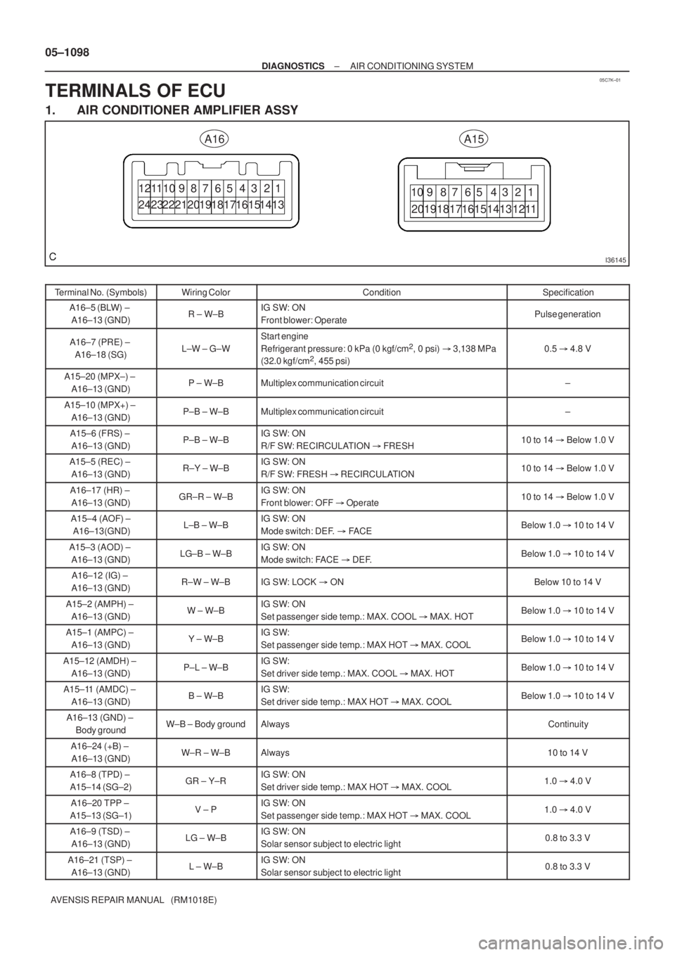
05C7K±01
I36145
A15A16
1211
2423 19 1615
20191817161514131211 8 7 6 5 4 3 2 1
10 9 8 7 6 5 4 3 2 1 10 9
2221 1817 141320 05±1098
± DIAGNOSTICSAIR CONDITIONING SYSTEM
AVENSIS REPAIR MANUAL (RM1018E)
TERMINALS OF ECU
1. AIR CONDITIONER AMPLIFIER ASSY
Terminal No. (Symbols)Wiring ColorConditionSpecification
A16±5 (BLW) ±
A16±13 (GND)R ± W±BIG SW: ON
Front blower: OperatePulse generation
A16±7 (PRE) ±
A16±18 (SG)L±W ± G±W
Start engine
Refrigerant pressure: 0 kPa (0 kgf/cm2, 0 psi) � 3,138 MPa
(32.0 kgf/cm2, 455 psi)
0.5 � 4.8 V
A15±20 (MPX±) ±
A16±13 (GND)P ± W±BMultiplex communication circuit±
A15±10 (MPX+) ±
A16±13 (GND)P±B ± W±BMultiplex communication circuit±
A15±6 (FRS) ±
A16±13 (GND)P±B ± W±BIG SW: ON
R/F SW: RECIRCULATION � FRESH10 to 14 � Below 1.0 V
A15±5 (REC) ±
A16±13 (GND)R±Y ± W±BIG SW: ON
R/F SW: FRESH � RECIRCULATION10 to 14 � Below 1.0 V
A16±17 (HR) ±
A16±13 (GND)GR±R ± W±BIG SW: ON
Front blower: OFF � Operate10 to 14 � Below 1.0 V
A15±4 (AOF) ±
A16±13(GND)L±B ± W±BIG SW: ON
Mode switch: DEF. � FACEBelow 1.0 � 10 to 14 V
A15±3 (AOD) ±
A16±13 (GND)LG±B ± W±BIG SW: ON
Mode switch: FACE � DEF.Below 1.0 � 10 to 14 V
A16±12 (IG) ±
A16±13 (GND)R±W ± W±BIG SW: LOCK � ONBelow 10 to 14 V
A15±2 (AMPH) ±
A16±13 (GND)W ± W±BIG SW: ON
Set passenger side temp.: MAX. COOL � MAX. HOTBelow 1.0 � 10 to 14 V
A15±1 (AMPC) ±
A16±13 (GND)Y ± W±BIG SW:
Set passenger side temp.: MAX HOT � MAX. COOLBelow 1.0 � 10 to 14 V
A15±12 (AMDH) ±
A16±13 (GND)P±L ± W±BIG SW:
Set driver side temp.: MAX. COOL � MAX. HOTBelow 1.0 � 10 to 14 V
A15±11 (AMDC) ±
A16±13 (GND)B ± W±BIG SW:
Set driver side temp.: MAX HOT � MAX. COOLBelow 1.0 � 10 to 14 V
A16±13 (GND) ±
Body groundW±B ± Body groundAlwaysContinuity
A16±24 (+B) ±
A16±13 (GND)W±R ± W±BAlways10 to 14 V
A16±8 (TPD) ±
A15±14 (SG±2)GR ± Y±RIG SW: ON
Set driver side temp.: MAX HOT � MAX. COOL1.0 � 4.0 V
A16±20 TPP ±
A15±13 (SG±1)V ± PIG SW: ON
Set passenger side temp.: MAX HOT � MAX. COOL1.0 � 4.0 V
A16±9 (TSD) ±
A16±13 (GND)LG ± W±BIG SW: ON
Solar sensor subject to electric light0.8 to 3.3 V
A16±21 (TSP) ±
A16±13 (GND)L ± W±BIG SW: ON
Solar sensor subject to electric light0.8 to 3.3 V
Page 1183 of 5135

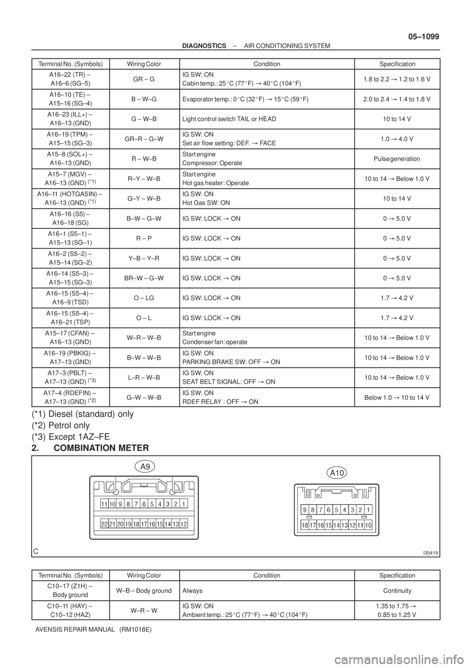
I35419
A10A9
± DIAGNOSTICSAIR CONDITIONING SYSTEM
05±1099
AVENSIS REPAIR MANUAL (RM1018E)Terminal No. (Symbols)Specification Condition Wiring Color
A16±22 (TR) ±
A16±6 (SG±5)GR ± GIG SW: ON
Cabin temp.: 25�C (77�F) � 40�C (104�F)1.8 to 2.2 � 1.2 to 1.6 V
A16±10 (TE) ±
A15±16 (SG±4)B ± W±GEvaporator temp.: 0�C (32�F) � 15�C (59�F)2.0 to 2.4 � 1.4 to 1.8 V
A16±23 (ILL+) ±
A16±13 (GND)G ± W±BLight control switch TAIL or HEAD10 to 14 V
A16±19 (TPM) ±
A15±15 (SG±3)GR±R ± G±WIG SW: ON
Set air flow setting: DEF. � FACE1.0 � 4.0 V
A15±8 (SOL+) ±
A16±13 (GND)R ± W±BStart engine
Compressor: OperatePulse generation
A15±7 (MGV) ±
A16±13 (GND) (*1)R±Y ± W±BStart engine
Hot gas heater: Operate10 to 14 � Below 1.0 V
A16±11 (HOTGASIN) ±
A16±13 (GND) (*1)G±Y ± W±BIG SW: ON
Hot Gas SW: ON10 to 14 V
A16±16 (S5) ±
A16±18 (SG)B±W ± G±WIG SW: LOCK � ON0 � 5.0 V
A16±1 (S5±1) ±
A15±13 (SG±1)R ± PIG SW: LOCK � ON0 � 5.0 V
A16±2 (S5±2) ±
A15±14 (SG±2)Y±B ± Y±RIG SW: LOCK � ON0 � 5.0 V
A16±14 (S5±3) ±
A15±15 (SG±3)BR±W ± G±WIG SW: LOCK � ON0 � 5.0 V
A16±15 (S5±4) ±
A16±9 (TSD)O ± LGIG SW: LOCK � ON1.7 � 4.2 V
A16±15 (S5±4) ±
A16±21 (TSP)O ± LIG SW: LOCK � ON1.7 � 4.2 V
A15±17 (CFAN) ±
A16±13 (GND)W±R ± W±BStart engine
Condenser fan: operate10 to 14 � Below 1.0 V
A16±19 (PBKIG) ±
A17±13 (GND)B±W ± W±BIG SW: ON
PARKING BRAKE SW: OFF � ON10 to 14 � Below 1.0 V
A17±3 (PBLT) ±
A17±13 (GND) (*3)L±R ± W±BIG SW: ON
SEAT BELT SIGNAL: OFF � ON10 to 14 � Below 1.0 V
A17±4 (RDEFIN) ±
A17±13 (GND) (*2)G±W ± W±BIG SW: ON
RDEF RELAY : OFF � ONBelow 1.0 � 10 to 14 V
(*1) Diesel (standard) only
(*2) Petrol only
(*3) Except 1AZ±FE
2. COMBINATION METER
Terminal No. (Symbols)Wiring ColorConditionSpecification
C10±17 (Z1H) ±
Body groundW±B ± Body groundAlwaysContinuity
C10±11 (HAY) ±
C10±12 (HAZ)W±R ± WIG SW: ON
Ambient temp.: 25�C (77�F) � 40�C (104�F)1.35 to 1.75 �
0.85 to 1.25 V
Page 1186 of 5135
I35410
BB WEngine Room R/B No.3Engine Room R/B No.1,
Engine Room J/B No.1Power Heater ECU
3 3 1A 1
12 PWR HTR
P15
+
FL MAIN
Battery
ECW±B W±BJ2
J/C
AAP11
± 1
± DIAGNOSTICSCOMBUSTION TYPE POWER HEATER SYSTEM
05±1171
AVENSIS REPAIR MANUAL (RM1018E)
ECU POWER SOURCE CIRCUIT
CIRCUIT DESCRIPTION
This is power source for the power heater ECU and power heater fuel pump.
WIRING DIAGRAM
05C80±01