Page 2550 of 5135

F13686
HoldTurn
C68609
30±20
±
DRIVE SHAFT / PROPELLER SHAFT FRONT DRIVE SHAFT
AVENSIS REPAIR MANUAL (RM1018E)
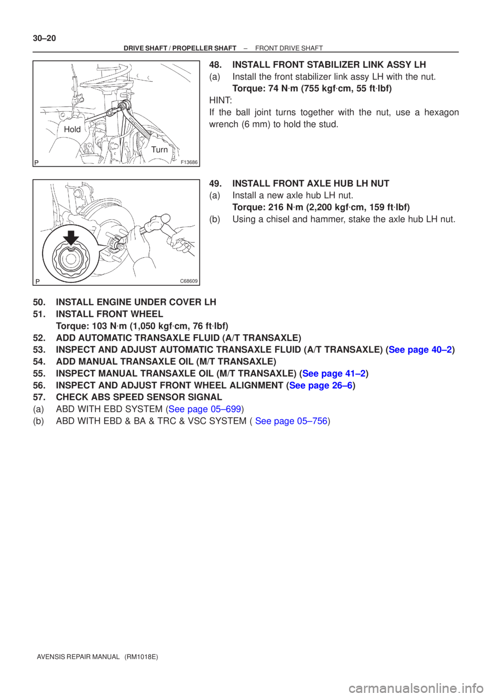
48.INSTALL FRONT STABILIZER LINK ASSY LH
(a)Install the front stabilizer link assy LH with the nut. Torque: 74 N �m (755 kgf �cm, 55 ft �lbf)
HINT:
If the ball joint turns together with the nut, use a hexagon
wrench (6 mm) to hold the stud.
49.INSTALL FRONT AXLE HUB LH NUT
(a)Install a new axle hub LH nut. Torque: 216 N �m (2,200 kgf �cm, 159 ft �lbf)
(b)Using a chisel and hammer, stake the axle hub LH nut.
50.INSTALL ENGINE UNDER COVER LH
51.INSTALL FRONT WHEEL Torque: 103 N �m (1,050 kgf �cm, 76 ft �lbf)
52.ADD AUTOMATIC TRANSAXLE FLUID (A/T TRANSAXLE)
53.INSPECT AND ADJUST AUTOMATIC TRANSAXLE FLUID (A/T TRANSAXLE) (See page 40±2)
54. ADD MANUAL TRANSAXLE OIL (M/T TRANSAXLE)
55.INSPECT MANUAL TRANSAXLE OIL (M/T TRANSAXLE) (See page 41±2)
56.INSPECT AND ADJUST FRONT WHEEL ALIGNMENT (See page 26±6)
57. CHECK ABS SPEED SENSOR SIGNAL
(a)ABD WITH EBD SYSTEM (See page 05±699)
(b)ABD WITH EBD & BA & TRC & VSC SYSTEM ( See page 05±756)
Page 2555 of 5135
3005C±02
±
DRIVE SHAFT / PROPELLER SHAFT DRIVE SHAFT, PROPELLER SHAFT, AXLE
30±1
AVENSIS REPAIR MANUAL (RM1018E)
DRIVE SHAFT, PROPELLER SHAFT, AXLE
PROBLEM SYMPTOMS TABLE
Use the table below to help you find the cause of the problem. The numbers \
indicate the priority of
the likely cause of the problem. Check each part in order. If necessary, replace these parts.
SymptomSuspect AreaSee page
Wander
5. Wheel
6. Front wheel alignment
7. Rear wheel alignment
8. Hub bearing (Worn)
9. Front shock absorber
10.Rear shock absorber28±1
26±6
27±4
30±2
26±10
27±8
Front wheel shimmy
1. Wheel (Imbalance)
2. Hub bearing (Worn)
3. Lower suspension arm ATM:
4. Lower suspension arm MTM:
5. Lower ball joint (Worm)
6. Front shock absorber28±1
30±2
26±16
26±21
26±24
26±10
Noise (Front)
1. Front drive shaft
2. Front shock absorber
3. Hub bearing (Worn)
4. Lower ball joint (Worm)30±6
26±10 30±2
26±24
Noise (Rear)1. Hub bearing (Worn)
2. Rear shock absorber30±2
27±8
Page 2570 of 5135
G23874
G23868
G23880
G23881
G23865
27±20
± REAR SUSPENSIONREAR SUSPENSION ARM ASSY NO.1 LH
AVENSIS REPAIR MANUAL (RM1018E)
(b) Install the rear side rear suspension arm assy No.1 LH,
and temporarily tighten bolt and nut.
NOTICE:
When installing the bolt, hold the nut not to rotate.
(c) Install the 3 bolts.
Torque: 65 N�m (663 kgf�cm, 48 ft�lbf)
(d) Install the front side rear axle carrier sub±assy LH to the
rear suspension arm assy No.1 LH, and temporarily tight-
en the nut.
(e) Install the axle carrier sub±assy LH to the rear suspension
arm assy No.1 LH, and temporarily tighten the bolt and
nut.
(f) Install the rear shock absorber with coil spring to the rear
suspension arm assy No.1 LH, and temporarily tighten
the bolt and nut.
Page 2573 of 5135
G23881
������G25777
G23871
±
REAR SUSPENSION REAR SUSPENSION ARM ASSY NO.1 LH
27±23
AVENSIS REPAIR MANUAL (RM1018E)
(f) Fully tighten the bolt and nut.
Torque: 74 N �m (755 kgf �cm, 55 ft �lbf)
NOTICE:
When installing the bolt, hold the nut not to rotate.
17. FULLY TIGHTEN LOWER CONTROL ARM ASSY LH
NOTICE:
Be sure to empty the vehicle when fully tightening the bolt
and nut.
(a) Fully tighten the nut. Torque: 60 N �m (612 kgf �cm, 44 ft �lbf)
(b) Install the clip.
NOTICE:
�When the holes for the clip are not aligned, adjust
them by tightening the nut. The tightening angle for
the adjustment must be less than 60 �.
�Insert the clip from the rear side of a vehicle.
(c) Fully tighten the bolt. Torque: 105 N �m (1,071 kgf �cm, 77 ft �lbf)
18.INSPECT AND ADJUST REAR WHEEL ALIGNMENT (See page 27±4)
19. CHECK ABS SPEED SENSOR SIGNAL
(a)ABD WITH EBD SYSTEM (See page 05±699)
(b)ABD WITH EBD & BA & TRC & VSC SYSTEM ( See page 05±756)
Page 2576 of 5135
F45161
Brake Master
Cylinder Sub±assy
Clutch Master Cylinder AssyM/T Transaxle: Vacuum Tank Diesel Engine Type:
Brake Fulid Level
Switch Connector Accelerator Control
Cable Support
20 (204, 15)
19 (194, 14)
Clutch Reservoir
Hose M/T Transaxle: Brake Booster Assy� Brake Booster Gasket
Brake Master Cylinder
ClevisClip Clevis Pin
13 (130, 9)
15 (155, 11) *1
29 (296, 21) *2
15 (155, 11)
N�m (kgf�cm, ft�lbf)
: Specified torque
5.4 (55, 48 in.�lbf)
8.3 (85, 73 in.�lbf)
Wave Washer
Check Valve Grommet
15 (155, 11)
5.4 (55, 48 in.�lbf)
*1 w/ ABS:
*2 w/ VSC:
32±24
± BRAKEBRAKE BOOSTER ASSY (RHD)
AVENSIS REPAIR MANUAL (RM1018E)
Page 2580 of 5135
320VU±01
F45162
Vacuum Hose
ClipBrake Vacuum
Check Valve
Check Valve
Grommet
Clevis Pin
Clip Wave Washer
13 (130, 9)
Engine Room Relay Block Way
Clutch Reservoir Tube M/T Transaxle:
Front Brake
Tube No.5
15 (155, 11) *1
29 (296, 21) *2
Brake Fluid Level
Switch Connector
� Brake Booster Gasket
20 (204, 15)
20 (204, 15)
Brake Master
Cylinder Sub±assy
� Brake Booster Assy
Brake Master
Cylinder clevis
15 (155, 11)
Fuel Filter Assy Diesel Engine Type: Heater Assy w/ Cold Area:
Air Cleaner Assembly
With Hose
Clutch Tube M/T Transaxle:Gasoline Engine Type:
15 (155, 11)
*1
w/ ABS:
*2
w/ VSC:N�m (kgf�cm, ft�lbf) : Specified torque
5.4 (55, 48 in.�lbf)
Charcoal Canister
Assy
32±18
± BRAKEBRAKE BOOSTER ASSY (LHD)
AVENSIS REPAIR MANUAL (RM1018E)
COMPONENTS
Page 2586 of 5135
320W5±01
G24285
LHD Steering Position Type:
Charcoal Canister Assy
Brake Fluid Level
Switch Connector
Clutch Reservoir
Tube M/T Transaxle:Brake Booster Assy
Clip
Way
20 (204, 15)
15 (155, 11)
15 (155, 11)*1
29 (296, 21)*2
15 (155, 11)*1
29 (296, 21)*2
Brake Master
Cylinder Sub±assy
20 (204, 15)
Engin Room Relay Block
RHD Steering Position Type:Air Cleaner Cap Sub±assy
Brake Fluid Level
Switch ConnectorBrake Master
Cylinder Sub±assy
Clip
Accelerator Control
Cable Support
20 (204, 15)
*1
w/ ABS:*2 w/ VSC:N�m (kgf�cm, ft�lbf) : Specified torque
15 (155, 11)*1
29 (296, 21)*2
15 (155, 11)*1
29 (296, 21)*2
Clutch Reservoir
Tube M/T Transaxle:
Brake Booster Assy
5.4 (55, 48 in.�lbf)
Fuel Filter Assy Diesel Engin Type:
± BRAKEBRAKE MASTER CYLINDER SUB±ASSY
32±11
AVENSIS REPAIR MANUAL (RM1018E)
BRAKE MASTER CYLINDER SUB±ASSY
COMPONENTS
Page 2603 of 5135

±
DRIVE SHAFT / PROPELLER SHAFT REAR AXLE CARRIER SUB±ASSY LH
30±35
AVENSIS REPAIR MANUAL (RM1018E)
34. FULLY TIGHTEN UPPER CONTROL ARM ASSY
(a) Fully tighten the bolt.
Torque: 74 N �m (755 kgf �cm, 55 ft �lbf)
NOTICE:
When installing the bolt, hold the nut not to rotate.
35. FULLY TIGHTEN REAR SUSPENSION ARM ASSY NO.1 LH
(a) Fully tighten the nut (ball joint side). Torque: 105 N �m (1,071 kgf �cm, 77 ft �lbf)
(b) Install the clip.
NOTICE:
If the holes for the clip are not aligned, tighten the nut up to 60 � further.
(c) Fully tighten the bolt and nut.
Torque: 74 N �m (755 kgf �cm, 55 ft �lbf)
NOTICE:
When installing the bolt, hold the nut not to rotate.
36. FULLY TIGHTEN LOWER CONTROL ARM ASSY LH
(a) Fully tighten the nut. Torque: 60 N �m (612 kgf �cm, 44 ft �lbf)
(b) Install the clip.
NOTICE:
If the holes for the clip are not aligned, tighten the nut up to 60 � further.
(c) Fully tighten the bolt (member side). Torque: 105 N �m (1,071 kgf �cm, 77 ft �lbf)
NOTICE:
When installing the bolt, hold the nut not to rotate.
37.INSPECT AND ADJUST PARKING BRAKE LEVER TRAVEL (See page 33±2)
38.INSPECT AND ADJUST REAR WHEEL ALIGNMENT (See page 27±4)
39. CHECK ABS SPEED SENSOR SIGNAL
(a)ABD WITH EBD SYSTEM (See page 05±699)
(b)ABD WITH EBD & BA & TRC & VSC SYSTEM ( See page 05±756)