Page 2340 of 5135
14±304
±
ENGINE MECHANICAL PARTIAL ENGINE ASSY (1CD±FTV)
AVENSIS REPAIR MANUAL (RM1018E)
191. INSTALL AIR CLEANER ASSY Torque: 7.0 N �m (71 kgf �cm, 62 in. �lbf)
192. INSTALL ENGINE COVER NO.1
Torque: 8.0 N �m (82 kgf �cm, 71 in. �lbf)
193.BLEED CLUTCH PIPE LINE (See page 42±17)
194. INSTALL FRONT WHEELS Torque: 103 N �m (1,050 kgf �cm, 76 ft �lbf)
195. ADD MANUAL TRANSAXLE OIL
196. ADD ENGINE OIL
197.ADD ENGINE COOLANT (See page 16±44)
198. CHECK CLUTCH FLUID LEAKAGE
199. CHECK FLUID LEVEL IN RESERVOIR
200. CHECK BRAKE FLUID LEAKAGE
201. CHECK FOR ENGINE OIL LEAKS
202.CHECK FOR FUEL LEAKS (See page 11±60)
203.CHECK FOR ENGINE COOLANT LEAKS (See page 16±44)
204. CHECK FOR EXHAUST GAS LEAKS
205.INSPECT AND ADJUST FRONT WHEEL ALIGNMENT (See page 26±6)
206.INSPECT ENGINE IDLE SPEED (See page 14±266)
207.CHECK ABS SPEED SENSOR SIGNAL (See page 05±756)
Page 2459 of 5135
260DP±01
F44614
Front Shock Absorber with Coil Spring
Front Stabilizer Link Assy LH
47 (479, 35)
220 (2,240, 162)
74 (755, 55)
19 (194, 14)
Speed Sensor
Front LH
Front Flexible Hose
Front Suspension Support Dust Cover LH
Front Suspension Support Sub±assy LH
Front Suspension
Support LH Dust Seal
Front Coil Spring
Seat Upper LH
Front Axle Assy
Front Coil Spring Insulator Upper LH
Front Coil Spring LH
N�m (kgf�cm, ft�lbf) : Specified torque
�Non±reusable part
Front Spring
Bumper LH
Front Coil
Spring Insulator
Lower LH
Shock Absorber
Assy Front LH
39 (398, 29)
� 26±2
± FRONT SUSPENSIONFRONT SUSPENSION
AVENSIS REPAIR MANUAL (RM1018E)
FRONT SUSPENSION
COMPONENTS
Page 2461 of 5135
F44616
89 (908, 66)
102 (1,040, 75)
220 (2,240, 162)
8 (82, 71 in.�lbf)
49 (500, 36)
103 (1,050, 76)
216 (2,200, 159)
Front Shock Absorber with Coil Spring
Front Drive Shaft Assy LHSpeed Sensor Front LH
Cotter Pin
Front Disc
Tie Rod End
Sub±assy LH
Cotter Pin
Front Disc Brake
Caliper Assy LH
Front Suspension Arm
Sub±assy Lower No.1 LH
Lower Ball Joint Assy Front LH
Front Axle Assy LHFront Axle Hub LH Nut
N�m (kgf�cm, ft�lbf) : Specified torque
�Non±reusable part�
�� 26±4
± FRONT SUSPENSIONFRONT SUSPENSION
AVENSIS REPAIR MANUAL (RM1018E)
Page 2463 of 5135

2600K±06
±
FRONT SUSPENSION FRONT SUSPENSION SYSTEM
26±1
AVENSIS REPAIR MANUAL (RM1018E)
FRONT SUSPENSION SYSTEM
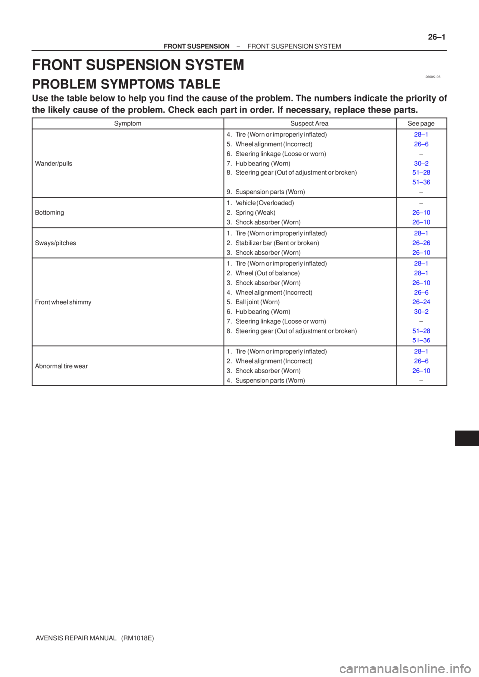
PROBLEM SYMPTOMS TABLE
Use the table below to help you find the cause of the problem. The numbers \
indicate the priority of
the likely cause of the problem. Check each part in order. If necessary, replace these parts.
SymptomSuspect AreaSee page
Wander/pulls
4. Tire (Worn or improperly inflated)
5. Wheel alignment (Incorrect)
6. Steering linkage (Loose or worn)
7. Hub bearing (Worn)
8. Steering gear (Out of adjustment or broken)
9. Suspension parts (Worn)28±1
26±6
±
30±2
51±28
51±36
±
Bottoming
1. Vehicle (Overloaded)
2. Spring (Weak)
3. Shock absorber (Worn)±
26±10
26±10
Sways/pitches
1. Tire (Worn or improperly inflated)
2. Stabilizer bar (Bent or broken)
3. Shock absorber (Worn)28±1
26±26
26±10
Front wheel shimmy
1. Tire (Worn or improperly inflated)
2. Wheel (Out of balance)
3. Shock absorber (Worn)
4. Wheel alignment (Incorrect)
5. Ball joint (Worn)
6. Hub bearing (Worn)
7. Steering linkage (Loose or worn)
8. Steering gear (Out of adjustment or broken)28±1
28±1
26±10 26±6
26±24
30±2 ±
51±28
51±36
Abnormal tire wear
1. Tire (Worn or improperly inflated)
2. Wheel alignment (Incorrect)
3. Shock absorber (Worn)
4. Suspension parts (Worn)28±1
26±6
26±10 ±
Page 2490 of 5135
270E2±01
G23870
27±14
± REAR SUSPENSIONREAR SHOCK ABSORBER WITH COIL SPRING
AVENSIS REPAIR MANUAL (RM1018E)
DISPOSAL
1. DISPOSE OF SHOCK ABSORBER ASSY REAR LH
(a) Fully extend the shock absorber rod.
(b) Using a drill, make a hole in the cylinder as shown in the
illustration to discharge the gas inside the cylinder.
CAUTION:
�When drilling, since the fragments may fly out, work
carefully.
�The discharged gas is colorless, odorless and non±
poisonous.
Page 2491 of 5135

270E8±01
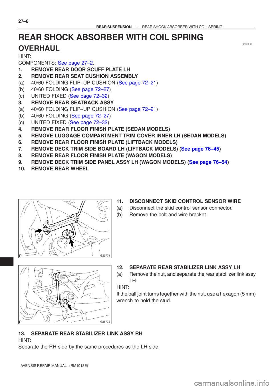
G25771
G25772
27±8
±
REAR SUSPENSION REAR SHOCK ABSORBER WITH COIL SPRING
AVENSIS REPAIR MANUAL (RM1018E)
REAR SHOCK ABSORBER WITH COIL SPRING
OVERHAUL
HINT:
COMPONENTS: See page 27±2.
1. REMOVE REAR DOOR SCUFF PLATE LH
2. REMOVE REAR SEAT CUSHION ASSEMBLY
(a)40/60 FOLDING FLIP±UP CUSHION (See page 72±21)
(b)40/60 FOLDING (See page 72±27)
(c)UNITED FIXED (See page 72±32)
3. REMOVE REAR SEATBACK ASSY
(a)40/60 FOLDING FLIP±UP CUSHION (See page 72±21)
(b)40/60 FOLDING (See page 72±27)
(c)UNITED FIXED (See page 72±32)
4. REMOVE REAR FLOOR FINISH PLATE (SEDAN MODELS)
5. REMOVE LUGGAGE COMPARTMENT TRIM COVER INNER LH (SEDAN MODELS)
6. REMOVE REAR FLOOR FINISH PLATE (LIFTBACK MODELS)
7.REMOVE DECK TRIM SIDE BOARD LH (LIFTBACK MODELS) (See page 76±45)
8. REMOVE REAR FLOOR FINISH PLATE (WAGON MODELS)
9.REMOVE DECK TRIM SIDE PANEL ASSY LH (WAGON MODELS) (See page 76±54)
10. REMOVE REAR WHEEL 11. DISCONNECT SKID CONTROL SENSOR WIRE
(a) Disconnect the skid control sensor connector.
(b) Remove the bolt and wire bracket.
12. SEPARATE REAR STABILIZER LINK ASSY LH
(a) Remove the nut, and separate the rear stabilizer link assyLH.
HINT:
If the ball joint turns together with the nut, use a hexagon (5 mm)
wrench to hold the stud.
13. SEPARATE REAR STABILIZER LINK ASSY RH
HINT:
Separate the RH side by the same procedures as the LH side.
Page 2492 of 5135
G25775
G23865
G23866
G23867
G23868
± REAR SUSPENSIONREAR SHOCK ABSORBER WITH COIL SPRING
27±9
AVENSIS REPAIR MANUAL (RM1018E)
14. REMOVE REAR SHOCK ABSORBER WITH COIL
SPRING
(a) Support the rear suspension arm assy No.1 LH.
(b) Remove the bolt and nut from the rear suspension arm
assy No.1 LH.
NOTICE:
When removing the bolt, hold the nut not to rotate.
(c) Remove the 3 nuts.
(d) Remove the 2 bolts, and separate the parking brake cable
assy No.3.
(e) Remove the 3 bolts from the rear suspension arm assy
No.1 LH.
(f) Press the rear suspension arm assy No.1 LH down to the
outside of the vehicle and remove the rear shock absorb-
er with coil spring.
Page 2493 of 5135

C95735SST
�C95736
������
G24415
Rear shock
absorber
cushion
No.1
Rear
suspension
support
assy LH
G23869
F40128
SST 27±10
± REAR SUSPENSIONREAR SHOCK ABSORBER WITH COIL SPRING
AVENSIS REPAIR MANUAL (RM1018E)
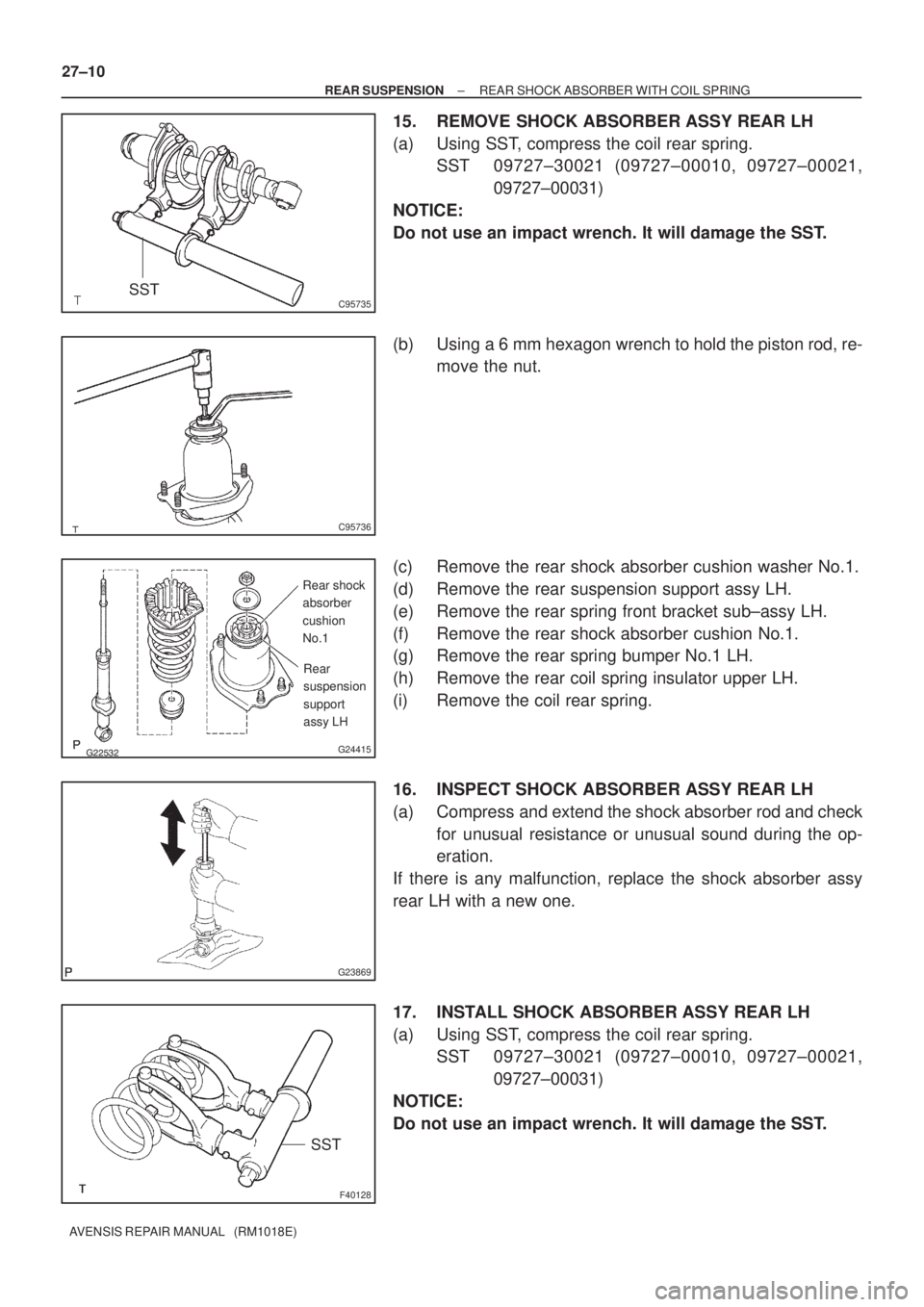
15. REMOVE SHOCK ABSORBER ASSY REAR LH
(a) Using SST, compress the coil rear spring.
SST 09727±30021 (09727±00010, 09727±00021,
09727±00031)
NOTICE:
Do not use an impact wrench. It will damage the SST.
(b) Using a 6 mm hexagon wrench to hold the piston rod, re-
move the nut.
(c) Remove the rear shock absorber cushion washer No.1.
(d) Remove the rear suspension support assy LH.
(e) Remove the rear spring front bracket sub±assy LH.
(f) Remove the rear shock absorber cushion No.1.
(g) Remove the rear spring bumper No.1 LH.
(h) Remove the rear coil spring insulator upper LH.
(i) Remove the coil rear spring.
16. INSPECT SHOCK ABSORBER ASSY REAR LH
(a) Compress and extend the shock absorber rod and check
for unusual resistance or unusual sound during the op-
eration.
If there is any malfunction, replace the shock absorber assy
rear LH with a new one.
17. INSTALL SHOCK ABSORBER ASSY REAR LH
(a) Using SST, compress the coil rear spring.
SST 09727±30021 (09727±00010, 09727±00021,
09727±00031)
NOTICE:
Do not use an impact wrench. It will damage the SST.