Page 4392 of 5135

A85357
DPNR (Diesel Particulate−NOx Reduction System) Catalyst Monolithic Construction:
NO, PM
HC, CO N2, CO2
H
2O
Exhaust Gas Temperature
Sensor (on up stream) ECM
Exhaust Gas Temperature
Sensor (on down stream)
Wall −Flow Type:
Differential Pressure Sensor
Cross Section
Magnified ViewGas Flow
PM
Exhaust Gas
DPNR (Diesel Particulate −NOx Reduction System):
DPNR Catalytic
Converter
05
−466
−
DIAGNOSTICS ECD SYSTEM (1CD −FTV)(From September, 2003)
AVENSIS Supplement (RM 1045E)
DTC P2002 PARTICULATE TRAP EFFICIENCY BELOW
THRESHOLD (BANK 1)
HINT:
S For more information on the DPNR (* 1) catalytic converter and TOYOTA D −CAT (*2), see page
05 −255.
S If P2002 is present, refer to the diagnostic trouble codes (DTCs) table for TOYOTA D −CAT on page
05 −255.
* 1 : Diesel Particulate −NOx Reduction system.
*2: Diesel Clean Advanced Technology.
CIRCUIT DESCRIPTION
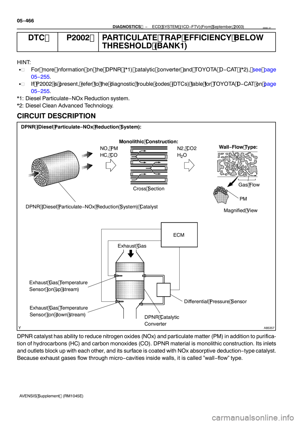
DPNR catalyst has ability to reduce nitrogen oxides (NOx) and particulate matter (PM) in addition to purifica-
tion of hydrocarbons (HC) and carbon monoxides (CO). DPNR material is monolithic construction. Its inlets
and outlets block up with each other, and its surface is coated with NOx absorptive deduction −type catalyst.
Because exhaust gases flow through micro −cavities inside walls, it is called ”wall −flow” type.
05I83 −01
Page 4676 of 5135
−
ENGINE MECHANICAL PARTIAL ENGINE ASSY (1CD −FTV)(From September,
2003)14 −135
AVENSIS Supplement (RM1045E)
228. INSPECT ENGINE IDLE SPEED (See page 14 −87)
229. CHECK ABS SPEED SENSOR SIGNAL (See Pub. No. RM1018E on page 05 −756)
Page 4731 of 5135

300N6−01
C53220F45751
SST
F13686
Hold
Turn
C80291
F44775
30−4
− DRIVE SHAFT / PROPELLER SHAFTFRONT DRIVE SHAFT (2AZ−FSE)
AVENSIS Supplement (RM1045E)
OVERHAUL
HINT:
Overhaul the RH side following the same procedure as for the LH side.
1. DRAIN AUTOMATIC TRANSAXLE FLUID (A/T TRANSAXLE)
(a) Remove the drain plug and gasket, and then drain the ATF.
(b) Install a new gasket and drain plug.
Torque: 49 N�m (500 kgf�cm, 36 ft�lbf)
2. REMOVE FRONT WHEEL
3. REMOVE ENGINE UNDER COVER LH
4. SEPARATE FRONT AXLE HUB LH NUT
(a) Using SST and a hammer, unstake the staked part of the
nut.
SST 09930−00010
(b) While applying the brake, remove the axle hub LH nut.
NOTICE:
Loosen the staked part of the lock nut completely, other-
wise the screw of the drive shaft may become damaged.
5. SEPARATE FRONT STABILIZER LINK ASSY LH
(a) Remove the nut and separate the front stabilizer link assy
LH from the shock absorber assy LH.
HINT:
If the ball joint turns together with the nut, use a hexagon
wrench (6 mm) to hold the stud.
6. DISCONNECT SPEED SENSOR FRONT LH
(a) Remove the bolt, and disconnect the speed sensor wire
and flexible hose from the shock absorber.
(b) Remove the bolt, and disconnect the speed sensor from
the steering knuckle.
NOTICE:
SBe careful not to damage the speed sensor.
SPrevent foreign matter from adhering to the speed
sensor.
Page 4733 of 5135

C83155
F40218
SST
C91598
C86265
30−6
− DRIVE SHAFT / PROPELLER SHAFTFRONT DRIVE SHAFT (2AZ−FSE)
AVENSIS Supplement (RM1045E)
11. REMOVE FRONT DRIVE SHAFT ASSY RH (RH DRIVE
SHAFT)
(a) Remove the 2 bolts and pull out the drive shaft together
with the center bearing bracket.
(b) Remove the drive shaft from the transaxle.
NOTICE:
SBe careful not to damage the oil seal, boot and dust
cover.
SBe careful not to drop the drive shaft assy.
12. FIX FRONT AXLE HUB LH BEARING
NOTICE:
The hub bearing may become damaged if subjected to the
vehicle weight. For example, moving the vehicle with the
drive shaft removed.
Therefore, if it is absolutely necessary to place the vehicle
weight on the hub bearing, first support it with SST.
SST 09608−16042 (09608−02021, 09608−02041)
13. INSPECT FRONT DRIVE SHAFT ASSY LH
(a) Check that there is no excessive play in the radial direc-
tion of the outboard joint.
(b) Check that the inboard joint slides smoothly in the thrust
direction.
(c) Check that there is no excessive play in the radial direc-
tion of the inboard joint.
(d) Check the boots for damage.
NOTICE:
Keep the drive shaft assy level during inspection.
14. REMOVE FRONT AXLE INBOARD JOINT BOOT
CLAMP
(a) Using pliers, remove the inboard joint boot LH No.2 clamp
as shown in the illustration.
(b) Remove the inboard joint boot LH clamp ifollwng the
same procedure as for the inboard joint boot LH No.2
clamp.
15. REMOVE FR AXLE INBOARD JOINT BOOT
(a) Remove the inboard joint boot from the inboard joint assy LH.
Page 4743 of 5135

F44775
C80291
F13686
Hold
Turn
C68609
30−16
− DRIVE SHAFT / PROPELLER SHAFTFRONT DRIVE SHAFT (2AZ−FSE)
AVENSIS Supplement (RM1045E)
45. INSTALL TIE ROD END SUB−ASSY LH
(a) Install the tie rod end sub−assy LH to the steering knuckle with the nut.
Torque: 49 N�m (500 kgf�cm, 36 ft�lbf)
(b) Install a new cotter pin.
NOTICE:
If the holes for the cotter pin are not aligned, tighten the nut up to 60_further.
46. CONNECT SPEED SENSOR FRONT LH
(a) Install the speed sensor front LH to the steering knuckle
with the bolt.
Torque: 8.0 N�m (82 kgf�cm, 71in.�lbf)
(b) Connect the speed sensor wire and flexible hose to the
shock absorber with the bolt.
Torque:19N�m(194 kgf�cm,14ft�lbf)
NOTICE:
SBe careful not to damage the speed sensor.
SKeep the speed sensor clean.
SDo not twist the sensor wire when installing the sen-
sor.
47. INSTALL FRONT STABILIZER LINK ASSY LH
(a) Install the front stabilizer link assy LH with the nut.
Torque: 74 N�m (755 kgf�cm, 55 ft�lbf)
HINT:
If the ball joint turns together with the nut, use a hexagon
wrench (6 mm) to hold the stud.
48. INSTALL FRONT AXLE HUB LH NUT
(a) Install a new axle hub LH nut.
Torque: 216N�m (2,200 kgf�cm,159 ft�lbf)
(b) Using a chisel and hammer, stake the axle hub LH nut.
Page 4744 of 5135
− DRIVE SHAFT / PROPELLER SHAFTFRONT DRIVE SHAFT (2AZ−FSE)
30−17
AVENSIS Supplement (RM1045E)
49. INSTALL ENGINE UNDER COVER LH
50. INSTALL FRONT WHEEL
Torque:103 N�m(1,050 kgf�cm, 76 ft�lbf)
51. ADD AUTOMATIC TRANSAXLE FLUID (A/T TRANSAXLE)
(SEE PUB. NO. RM1018E ON PAGE 40−2)
52. INSPECT AND ADJUST AUTOMATIC TRANSAXLE FLUID (A/T TRANSAXLE)
(SEE PUB. NO. RM1018E ON PAGE 40−2)
53. INSPECT AND ADJUST FRONT WHEEL ALIGNMENT (SEE PUB. NO. RM1018E ON PAGE 26−6)
54. CHECK ABS SPEED SENSOR SIGNAL
(a) ABD WITH EBD & BA & TRAC & VSC SYSTEM (SEE PUB. NO. RM1018E ON PAGE 5−756)
Page 4771 of 5135
D25834
SST
−
AUTOMATIC TRANSMISSION / TRANS FRONT DIFFERENTIAL OIL SEAL (U151E)
40−25
AVENSIS Supplement (RM1045E)
10. INSTALL DIFFERENTIAL SIDE BEARING RETAINER
OIL SEAL
(a) Using SST and a hammer, drive in a new oil seal. SST 09649 −17010, 09950 −70010 (09951 −07150)
Oil seal drive in depth:
0 �á 0.5 mm (0 �á 0.020 in.)
(b) Coat the lip of the oil seal with MP grease.
11 . INSTALL FRONT DRIVE SHAFT ASSY LH (SEE PAGE 30 −4)
1 2. INSTALL FRONT DRIVE SHAFT ASSY RH (SEE PAGE 30 −4)
1 3. INSTALL FRONT WHEELS
Torque: 103 N �m( 1,050 kgf �cm, 76 ft �lbf)
1 4. ADD AUTOMATIC TRANSAXLE FLUID (SEE PUB. NO. RM 1018E, PAGE40 −2)
1 5. INSPECT AUTOMATIC TRANSAXLE FLUID (SEE PUB. NO. RM 1018E, PAGE40 −2)
1 6. CHECK ABS SPEED SENSOR SIGNAL
(a) ABS WITH EBD & BA &TRAC & VSC SYSTEM (SEE PUB, NO. RM1018E, PAGE 5 −756)
Page 5083 of 5135

A93669
14–26–
ENGINE MECHANICAL PARTIAL ENGINE ASSY (1ZZ–FE/3ZZ–FE)(From
February, 2004)
AVENSIS REPAIR MANUAL SUPPLEMENT
(RM1098E)
137. INSTALL BATTERY
Torque:
5.0 N ⋅m (51 kgf ⋅cm, 44 in. ⋅lbf) for bolt
3.5 N ⋅m (36 kgf ⋅cm, 31 in. ⋅lbf) for nut
138. INSTALL RADIATOR SUPPORT NO.1
(a) Install the 2 radiator supports with the 2 bolts.
Torque: 19 N ⋅m (194 kgf ⋅cm, 14 ft ⋅lbf)
139. INSTALL AIR CLEANER CASE SUB–ASSY
(a) Install the air cleaner case with the 3 bolts.
Torque: 5.0 N ⋅m (51 kgf ⋅cm, 44 in. ⋅lbf)
140. INSTALL AIR CLEANER ASSEMBLY WITH HOSE (See page 10–6)
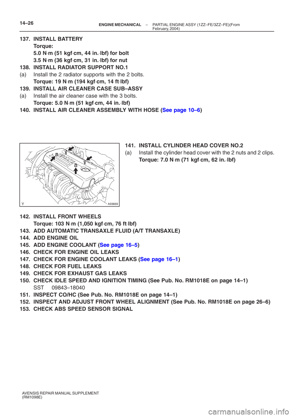
141. INSTALL CYLINDER HEAD COVER NO.2
(a) Install the cylinder head cover with the 2 nuts and 2 clips.
Torque: 7.0 N ⋅m (71 kgf ⋅cm, 62 in. ⋅lbf)
142. INSTALL FRONT WHEELS
Torque: 103 N ⋅m (1,050 kgf ⋅cm, 76 ft ⋅lbf)
143. ADD AUTOMATIC TRANSAXLE FLUID (A/T TRANSAXLE)
144. ADD ENGINE OIL
145. ADD ENGINE COOLANT (See page 16–5)
146. CHECK FOR ENGINE OIL LEAKS
147. CHECK FOR ENGINE COOLANT LEAKS (See page 16–1)
148. CHECK FOR FUEL LEAKS
149. CHECK FOR EXHAUST GAS LEAKS
150. CHECK IDLE SPEED AND IGNITION TIMING (See Pub. No. RM1018E on page 14–1)
SST 09843–18040
151. INSPECT CO/HC (See Pub. No. RM1018E on page 14–1)
152. INSPECT AND ADJUST FRONT WHEEL ALIGNMENT (See Pub. No. RM1018E on page \
26–6)
153. CHECK ABS SPEED SENSOR SIGNAL