Page 2606 of 5135

G23168
F08658
SST
G23167
32±62
±
BRAKE SKID CONTROL SENSOR
AVENSIS REPAIR MANUAL (RM1018E)
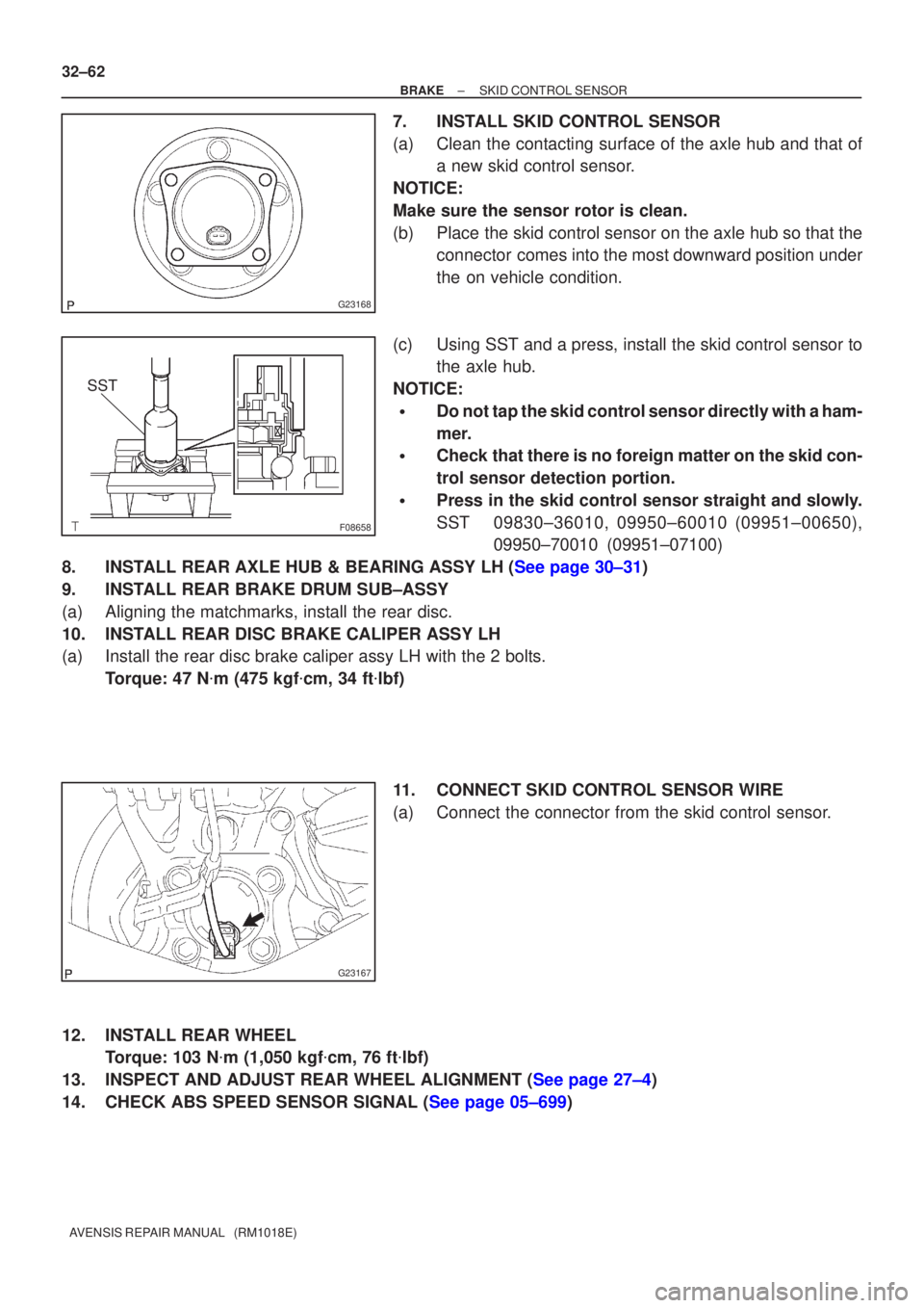
7. INSTALL SKID CONTROL SENSOR
(a) Clean the contacting surface of the axle hub and that of a new skid control sensor.
NOTICE:
Make sure the sensor rotor is clean.
(b) Place the skid control sensor on the axle hub so that the connector comes into the most downward position under
the on vehicle condition.
(c) Using SST and a press, install the skid control sensor to the axle hub.
NOTICE:
�Do not tap the skid control sensor directly with a ham-
mer.
�Check that there is no foreign matter on the skid con-
trol sensor detection portion.
�Press in the skid control sensor straight and slowly.
SST 09830±36010, 09950±60010 (09951±00650), 09950±70010 (09951±07100)
8.INSTALL REAR AXLE HUB & BEARING ASSY LH (See page 30±31)
9. INSTALL REAR BRAKE DRUM SUB±ASSY
(a) Aligning the matchmarks, install the rear disc.
10. INSTALL REAR DISC BRAKE CALIPER ASSY LH
(a) Install the rear disc brake caliper assy LH with the 2 bolts. Torque: 47 N �m (475 kgf �cm, 34 ft �lbf)
11. CONNECT SKID CONTROL SENSOR WIRE
(a) Connect the connector from the skid control sensor.
12. INSTALL REAR WHEEL Torque: 103 N �m (1,050 kgf �cm, 76 ft �lbf)
13.INSPECT AND ADJUST REAR WHEEL ALIGNMENT (See page 27±4)
14.CHECK ABS SPEED SENSOR SIGNAL (See page 05±699)
Page 2607 of 5135
3201P±05
G23166
F40024
G23165
G23165
± BRAKESPEED SENSOR FRONT LH
32±59
AVENSIS REPAIR MANUAL (RM1018E)
SPEED SENSOR FRONT LH
REPLACEMENT
HINT:
Replace the RH side by using the same procedures as those for the LH side.
1. REMOVE FRONT WHEEL
2. REMOVE FRONT FENDER LINER LH
3. REMOVE SPEED SENSOR FRONT LH
(a) Disconnect the resin clip and speed sensor wire harness
from the body and clamp.
(b) Disconnect the speed sensor connector.
(c) Remove the 2 clamp bolts holding the sensor harness
from the body and shock absorber.
(d) Remove the bolt and separate the speed sensor front LH.
NOTICE:
Prevent foeingn matter from attaching to the sensor tip.
4. INSTALL SPEED SENSOR FRONT LH
(a) Install the speed sensor front LH with the bolt.
Torque: 8.0 N�m (82 kgf�cm, 71 in.�lbf)
NOTICE:
Prevent foeingn matter from attaching to the sensor tip.
Page 2608 of 5135
F40024
A
B
G23166
32±60
±
BRAKE SPEED SENSOR FRONT LH
AVENSIS REPAIR MANUAL (RM1018E)
(b)Install the sensor harness clamp with the 2 bolts ºAº and ºBº to the body and shock absorber.
Torque:
Bolt A: 8.0 N �m (82 kgf �cm, 71 in. �lbf)
Bolt B: 29 N �m (296 kgf �cm, 21 ft �lbf)
NOTICE:
Do not twist the sensor wire when installing the sensor.
(c)Connect the speed sensor connector.
(d)Connect the resin clip and speed sensor wire harness to the body and clamp.
5.INSTALL FRONT FENDER LINER LH
6.INSTALL FRONT WHEEL Torque: 103 N �m (1,050 kgf �cm, 76 ft �lbf)
7.CHECK ABS SPEED SENSOR SIGNAL (See page 05±699)
Page 2672 of 5135
±
BRAKE STEERING SENSOR
32±67
AVENSIS REPAIR MANUAL (RM1018E)
20.CONNECT BATTERY NEGATIVE TERMINAL (See page 60±1)
21.INSPECT SRS WARNING LIGHT (See page 05±1184)
22.INSPECT ABS WARNING LIGHT AND VSC WARNING LIGHT (See page 05±756)
Page 2703 of 5135

D30342
D30341
BA
A
C81535
±
AUTOMATIC TRANSMISSION / TRANS AUTOMATIC TRANSAXLE ASSY (U241E)
40±35
AVENSIS REPAIR MANUAL (RM1018E)
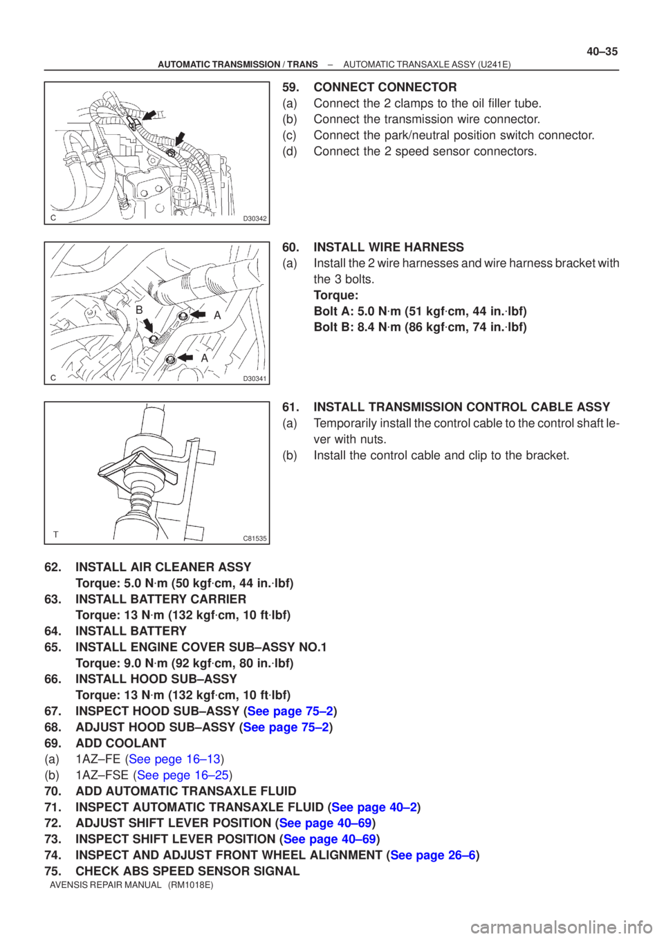
59. CONNECT CONNECTOR
(a) Connect the 2 clamps to the oil filler tube.
(b) Connect the transmission wire connector.
(c) Connect the park/neutral position switch connector.
(d) Connect the 2 speed sensor connectors.
60. INSTALL WIRE HARNESS
(a) Install the 2 wire harnesses and wire harness bracket with
the 3 bolts.
Torque:
Bolt A: 5.0 N �m (51 kgf �cm, 44 in. �lbf)
Bolt B: 8.4 N �m (86 kgf �cm, 74 in. �lbf)
61. INSTALL TRANSMISSION CONTROL CABLE ASSY
(a) Temporarily install the control cable to the control shaft le- ver with nuts.
(b) Install the control cable and clip to the bracket.
62. INSTALL AIR CLEANER ASSY Torque: 5.0 N �m (50 kgf �cm, 44 in. �lbf)
63. INSTALL BATTERY CARRIER Torque: 13 N �m (132 kgf �cm, 10 ft �lbf)
64. INSTALL BATTERY
65. INSTALL ENGINE COVER SUB±ASSY NO.1 Torque: 9.0 N �m (92 kgf �cm, 80 in. �lbf)
66. INSTALL HOOD SUB±ASSY
Torque: 13 N �m (132 kgf �cm, 10 ft �lbf)
67.INSPECT HOOD SUB±ASSY (See page 75±2)
68.ADJUST HOOD SUB±ASSY (See page 75±2)
69. ADD COOLANT
(a)1AZ±FE (See pege 16±13)
(b)1AZ±FSE (See pege 16±25)
70. ADD AUTOMATIC TRANSAXLE FLUID
71.INSPECT AUTOMATIC TRANSAXLE FLUID (See page 40±2)
72.ADJUST SHIFT LEVER POSITION (See page 40±69)
73.INSPECT SHIFT LEVER POSITION (See page 40±69)
74.INSPECT AND ADJUST FRONT WHEEL ALIGNMENT (See page 26±6)
75. CHECK ABS SPEED SENSOR SIGNAL
Page 2704 of 5135
40±36
±
AUTOMATIC TRANSMISSION / TRANS AUTOMATIC TRANSAXLE ASSY (U241E)
AVENSIS REPAIR MANUAL (RM1018E)
(a)ABS WITH EBD SYSTEM (See pege 05±699)
(b)ABS WITH EBD & BA &TRAC & VSC SYSTEM (See pege 05±756)
76. RESET MEMORY
(a)1AZ±FE (See pege 05±863)
(b)1AZ±FSE (See pege 05±920)
Page 2718 of 5135
40±22
±
AUTOMATIC TRANSMISSION / TRANS AUTOMATIC TRANSAXLE ASSY (U341E)
AVENSIS REPAIR MANUAL (RM1018E)
78.CHECK ABS SPEED SENSOR SIGNAL (See page 05±699)
79.RESET MEMORY (See page 05±985)
Page 2728 of 5135
D26133
SST(s)
D25304
0 to 5 mm
(0 to 0.20 in.)
41±6
±
MANUAL TRANSMISSION/TRANSAXLE FRONT DIFFERENTIAL OIL SEAL (E354/E357)
AVENSIS REPAIR MANUAL (RM1018E)
10. INSTALL TRANSMISSION CASE OIL SEAL
(a) Coat a new oil seal lip with MP grease.
(b) Using SST(s) and a hammer, install the oil seal. SST 09608±32010, 09950±70010 (09951±07200)
Drive in depth: 3.5 � 0.5 mm (0.138 � 0.020 in.)
NOTICE:
Be careful not to damage the oil seal lip.
11.INSTALL FRONT DRIVE SHAFT ASSY LH (See page 30±6)
12.INSTALL FRONT DRIVE SHAFT ASSY RH (See page 30±6)
13. INSTALL FRONT WHEELS Torque: 103 N �m (1,050 kgf �cm, 76 ft �lbf)
14. ADD MANUAL TRANSAXLE OIL Oil grade: API GL±4 or GL±5
Viscosity: SAE 75 W±90
Capacity: 2.5 liters (2.6 US qts, 2.2 lmp. qts)
Torque: 49 N �m (500 kgf �cm, 36 ft �lbf)
15.INSPECT MANUAL TRANSAXLE OIL (See page 41±2)
16.INSPECT FRONT WHEEL ALIGNMENT (See page 26±6)
17. CHECK ABS SPEED SENSOR SIGNAL
(a)w/ VSC (See page 05±756)
(b)w/o VSC (See page 05±699)