Page 3965 of 5135

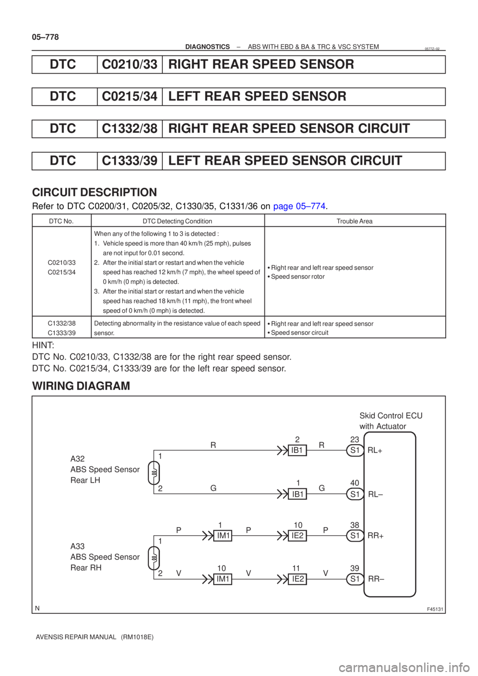
F45131
Skid Control ECU
with Actuator
A32
ABS Speed Sensor
Rear LH
A33
ABS Speed Sensor
Rear RH 23
RL+
S1
R
40RL±
S1
38
RR+
S1
39
RR±
S1
G
P
V
2 1
2 1 R
G
P
V P
V
2
IB1
1
IB1
10
11
10 1
IM1
IM1 IE2
IE2
05±778
±
DIAGNOSTICS ABS WITH EBD & BA & TRC & VSC SYSTEM
AVENSIS REPAIR MANUAL (RM1018E)
DTCC0210/33RIGHT REAR SPEED SENSOR
DTCC0215/34LEFT REAR SPEED SENSOR
DTCC1332/38RIGHT REAR SPEED SENSOR CIRCUIT
DTCC1333/39LEFT REAR SPEED SENSOR CIRCUIT
CIRCUIT DESCRIPTION
Refer to DTC C0200/31, C0205/32, C1330/35, C1331/36 on page 05±774.
DTC No.DTC Detecting ConditionTrouble Area
C0210/33
C0215/34
When any of the following 1 to 3 is detected :
1. Vehicle speed is more than 40 km/h (25 mph), pulses are not input for 0.01 second.
2. After the initial start or restart and when the vehicle speed has reached 12 km/h (7 mph), the wheel speed of
0 km/h (0 mph) is detected.
3. After the initial start or restart and when the vehicle speed has reached 18 km/h (11 mph), the front wheel
speed of 0 km/h (0 mph) is detected.
�Right rear and left rear speed sensor
� Speed sensor rotor
C1332/38
C1333/39Detecting abnormality in the resistance value of each speed
sensor.�Right rear and left rear speed sensor
� Speed sensor circuit
HINT:
DTC No. C0210/33, C1332/38 are for the right rear speed sensor.
DTC No. C0215/34, C1333/39 are for the left rear speed sensor.
WIRING DIAGRAM
0577Z±02
Page 3966 of 5135

F41836
F10180
12Connector 1
Connector 2
2
1
±
DIAGNOSTICS ABS WITH EBD & BA & TRC & VSC SYSTEM
05±779
AVENSIS REPAIR MANUAL (RM1018E)
INSPECTION PROCEDURE
HINT:
Start the inspection from step 1 if you are using the hand±held tester and\
start from step 2 if you are not using
the hand±held tester.
1READ VALUE OF HAND±HELD TESTER(REAR SPEED SENSOR)
(a)Select the item ºWHEEL SPEED RL (RR)º in the DATA LIST and read the value displayed on the hand±
held tester.
(b)Check that there is no difference between the speed value output from the speed sensor displayed on the hand±held tester and the speed value displayed on the speedometer when driving the vehicle.
OK:
There is almost no difference in the displayed speed value.
HINT:
There is tolerance of � 10 % in the speedometer indication.
OKGo to step 5
NG
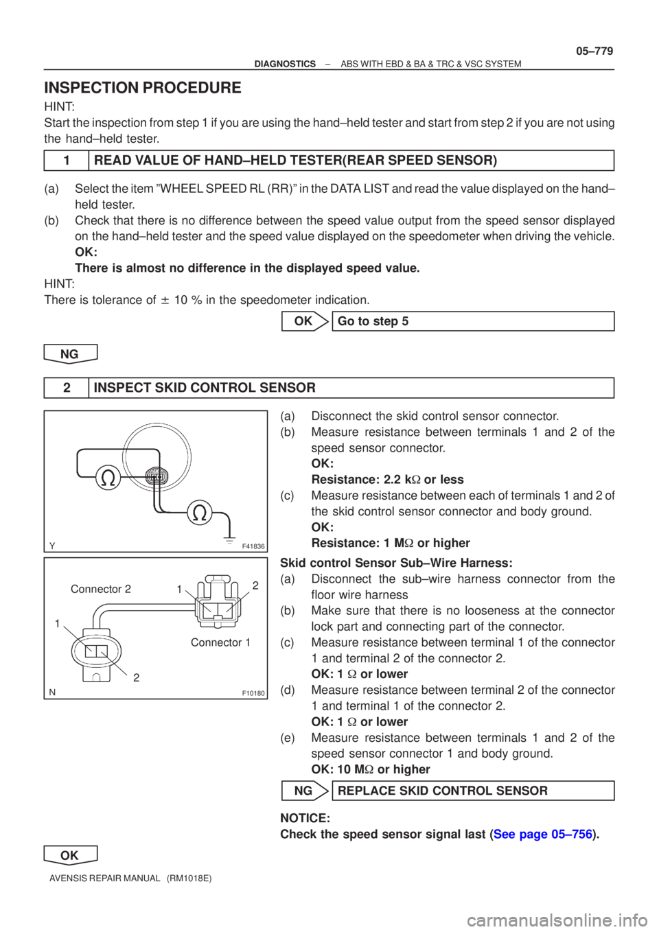
2INSPECT SKID CONTROL SENSOR
(a)Disconnect the skid control sensor connector.
(b)Measure resistance between terminals 1 and 2 of the speed sensor connector.
OK:
Resistance: 2.2 k �or less
(c)Measure resistance between each of terminals 1 and 2 of the skid control sensor connector and body ground.
OK:
Resistance: 1 M � or higher
Skid control Sensor Sub±Wire Harness:
(a)Disconnect the sub±wire harness connector from the floor wire harness
(b)Make sure that there is no looseness at the connector
lock part and connecting part of the connector.
(c)Measure resistance between terminal 1 of the connector 1 and terminal 2 of the connector 2.
OK: 1 � or lower
(d)Measure resistance between terminal 2 of the connector 1 and terminal 1 of the connector 2.
OK: 1 � or lower
(e)Measure resistance between terminals 1 and 2 of the speed sensor connector 1 and body ground.
OK: 10 M � or higher
NGREPLACE SKID CONTROL SENSOR
NOTICE:
Check the speed sensor signal last (See page 05±756).
OK
Page 3967 of 5135

W04200
Normal Signal Waveform
1 V / Division 2 m/s / Division GND
F10178OK
NG
05±780
±
DIAGNOSTICS ABS WITH EBD & BA & TRC & VSC SYSTEM
AVENSIS REPAIR MANUAL (RM1018E)
3CHECK HARNESS AND CONNECTOR(REAR SPEED SENSOR ± SKID CONTROL ECU)
(a)Check for an open or short circuit in harness and connector between each skid\
control sensor and the
skid control ECU (See page 01±32).
NGREPAIR OR REPLACE HARNESS ORCONNECTOR
OK
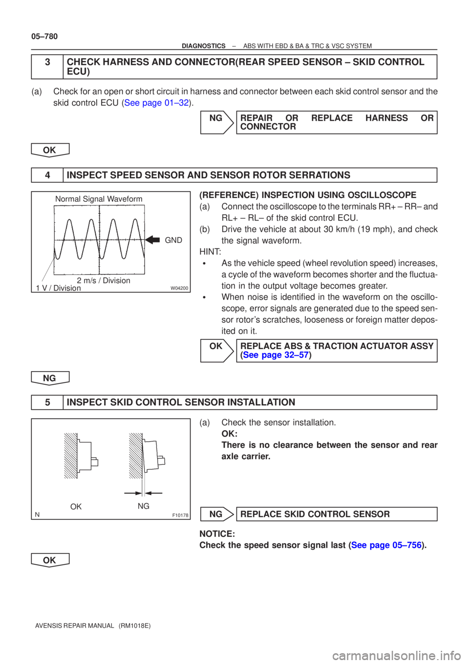
4INSPECT SPEED SENSOR AND SENSOR ROTOR SERRATIONS
(REFERENCE) INSPECTION USING OSCILLOSCOPE
(a)Connect the oscilloscope to the terminals RR+ ± RR± and RL+ ± RL± of the skid control ECU.
(b)Drive the vehicle at about 30 km/h (19 mph), and check the signal waveform.
HINT:
�As the vehicle speed (wheel revolution speed) increases,
a cycle of the waveform becomes shorter and the fluctua-
tion in the output voltage becomes greater.
�When noise is identified in the waveform on the oscillo-
scope, error signals are generated due to the speed sen-
sor rotor's scratches, looseness or foreign matter depos-
ited on it.
OKREPLACE ABS & TRACTION ACTUATOR ASSY (See page 32±57)
NG
5INSPECT SKID CONTROL SENSOR INSTALLATION
(a)Check the sensor installation. OK:
There is no clearance between the sensor and rear
axle carrier.
NGREPLACE SKID CONTROL SENSOR
NOTICE:
Check the speed sensor signal last (See page 05±756).
OK
Page 3968 of 5135
W04846
±
DIAGNOSTICS ABS WITH EBD & BA & TRC & VSC SYSTEM
05±781
AVENSIS REPAIR MANUAL (RM1018E)
6INSPECT SKID CONTROL SENSOR TIP
(a)Remove the skid control sensor (See page 32±61).
(b)Check the sensor tip.
OK:
No scratches or foreign objects on the sensor tip.
NGCLEAN OR REPAIR SKID CONTORL SENSOR
NOTICE:
Check the speed sensor signal last (See page 05±756).
OK
7INSPECT SENSOR ROTOR
(a)Check the sensor rotor serrations. OK:
No scratches, missing teeth or foreign objects.
NGREPLACE REAR AXLE HUB & BEARING ASSY RH
NGREPLACE REAR AXLE HUB & BEARING ASSY LH
NOTICE:
Check the speed sensor signal last (See page 05±756).
OK
REPLACE ABS & TRACTION ACTUATOR ASSY(See page 32±57)
NOTICE:
Do not reuse the skid control sensor.
Page 3969 of 5135
± DIAGNOSTICSABS WITH EBD & BA & TRC & VSC SYSTEM
05±835
AVENSIS REPAIR MANUAL (RM1018E)
ABS WARNING LIGHT CIRCUIT (DOES NOT LIGHT UP)
CIRCUIT DESCRIPTION
If the ECU detects trouble, it will prohibit ABS control, turn on the ABS warning light, and store the DTC.
Connect terminals Tc and CG of the DLC3 to make the ABS warning light blink and output the DTC.
0543F±04
Page 3970 of 5135
F45135
B±R
DH DA18 2Driver Side J/B
IGNWA S136
IE117 9
B±W
C11 C10Combination Meter
ABSSkid Control ECU
with Actuator
R±Y R±Y 22
17
C10
AM1
4B 4A11IG1
A 1
2 AM2
3
IK 1A
Engine Room R/B No.3 Engine Room R/B No.1 & Engine Room J/B No.1
1
3 Engine Room J/B No.41
IO ILJ15
J/C
Battery
*1: 1AZ±FSE
*2: 1CD±FTV
*3: LHD
*4: RHD(*3) (*4) (*3) (*4)B±W CA CA
J8 J26 J8 J26J/C
B±R
IE4 IP111
(*3) (*4) B±R
B (*2)B±G (*1)
B (*2)
FL MAINB±G (*1)
W±B (*3 *2)
W±B (*3 *1)A A
AAJ17
J/C
J16
J/C W±B
(*3) W±B (*4) W±B (*4)
I13
Ignition SW
46 05±836
± DIAGNOSTICSABS WITH EBD & BA & TRC & VSC SYSTEM
AVENSIS REPAIR MANUAL (RM1018E)
WIRING DIAGRAM
Page 3971 of 5135
±
DIAGNOSTICS ABS WITH EBD & BA & TRC & VSC SYSTEM
05±837
AVENSIS REPAIR MANUAL (RM1018E)
INSPECTION PROCEDURE
HINT:
Start the inspection from step 1 if you are using the hand±held tester and\
start from step 2 if you are not using
the hand±held tester.
1PERFORM ACTIVE TEST BY HAND±HELD TESTER(ABS WARNING LIGHT)
(a)Check that ºONº and ºOFFº of the ABS warning light is shown on th\
e combination meter by the hand±
held tester.
OKREPLACE ABS & TRACTION ACTUATOR ASSY(See page 32±57)
NG
2 INSPECT ABS WARNING LIGHT
(a)See combination meter troubleshooting on page 71±1. NG REPAIR OR REPLACE COMBINATION METERASSEMBLY
OK
3 CHECK HARNESS AND CONNECTOR(SKID CONTORL ECU ± CMBINATION METER)
(a) Check for an open or short circuit in harness and connector between the skid \
control ECU and com-
bination meter (See page 01±32).
NG REPAIR OR REPLACE HARNESS ORCONNECTOR
OK
REPLACE ABS & TRACTION ACTUATOR ASSY(See page 32±57)
Page 3972 of 5135
05±844
± DIAGNOSTICSABS WITH EBD & BA & TRC & VSC SYSTEM
AVENSIS REPAIR MANUAL (RM1018E)
TRC OFF INDICATOR, TRC CUT SWITCH CIRCUIT
CIRCUIT DESCRIPTION
This is the TRC control main switch. When the TRC OFF switch is pressed, TRC control goes off and the
TRC OFF indicator illuminates. Also, turn the TRC OFF indicator light to ºONº when the VSC system is at
the fail safe control. If the ignition switch is turned off, TRC control surely comes on the next time the ignition
switch is turned ON.
0543I±04