Page 552 of 5135
05±474
±
DIAGNOSTICS SFI SYSTEM(1AZ±FSE)
AVENSIS REPAIR MANUAL (RM1018E)
DTCP0705TRANSMISSION RANGE SENSOR CIRCUIT MALFUNCTION (PRNDL INPUT)
CIRCUIT DESCRIPTION
The park/neutral position switch goes on when the shift lever is in the N o\
r P shift position. If the shift lever
is moved from the N position to the D position, this signal is used for \
air±fuel ratio correction and for idle speed
control (estimated control), etc.
DTC No.DTC Detection ConditionTrouble Area
P07052 or more switches are ON simultaneously for N, P, D and R
positions (2 trip detection logic)�Short in park/neutral position switch circuit
� Park/neutral position switch
� ECM
HINT:
After confirming DTC P0705, use the hand±held tester to confirm the park/n\
eutral position switch signal from
the ºDIAGNOSIS / OBD/MOBD / DATA LIST / ALLº.
WIRING DIAGRAM
Refer to DTC P0705 on page 05±938.
INSPECTION PROCEDURE
Refer to DTC P0705 on page 05±938.
05CJ8±01
Page 554 of 5135

05±472
±
DIAGNOSTICS SFI SYSTEM(1AZ±FSE)
AVENSIS REPAIR MANUAL (RM1018E)
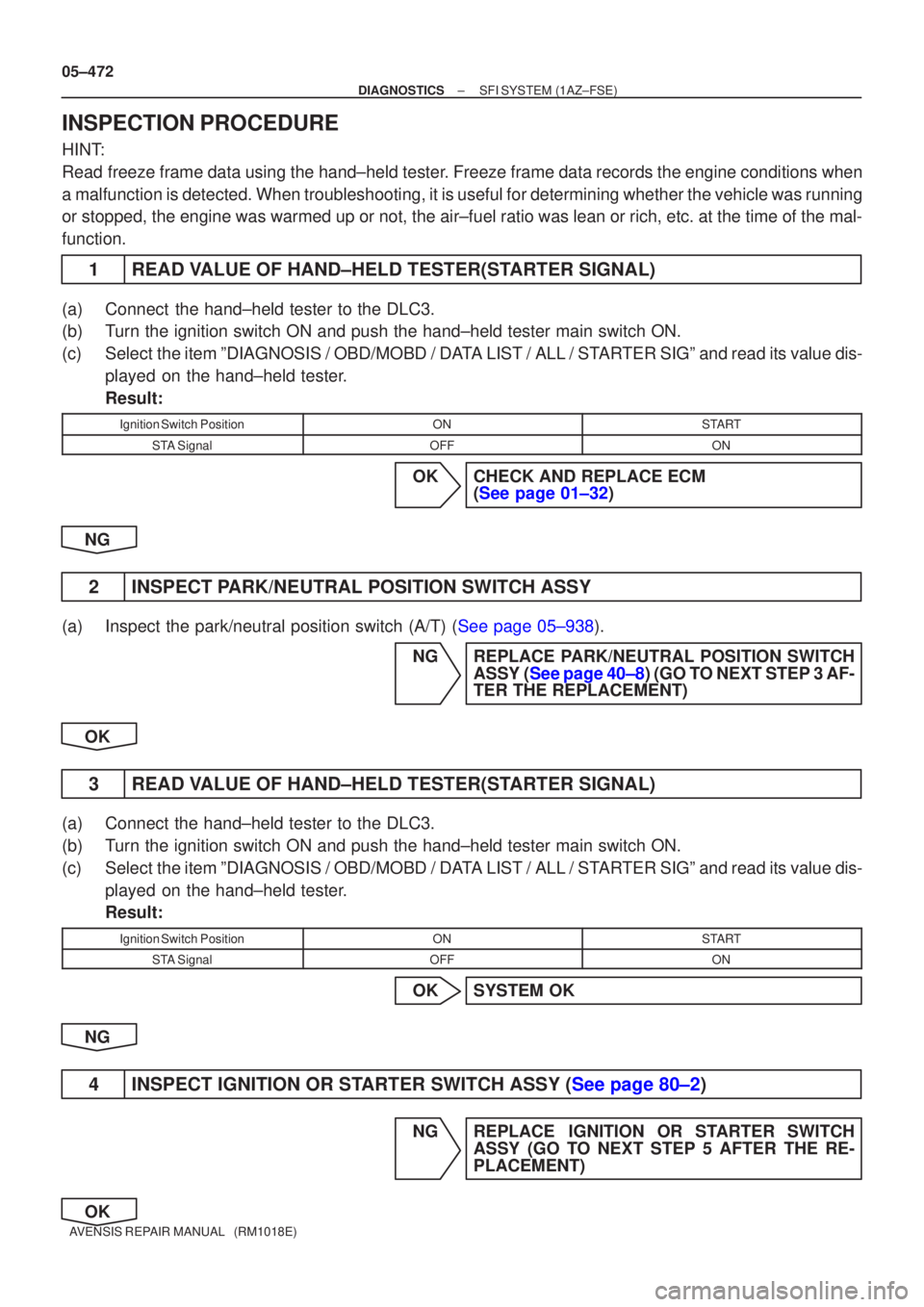
INSPECTION PROCEDURE
HINT:
Read freeze frame data using the hand±held tester. Freeze frame data records the engine conditions when
a malfunction is detected. When troubleshooting, it is useful for determi\
ning whether the vehicle was running
or stopped, the engine was warmed up or not, the air±fuel ratio was lea\
n or rich, etc. at the time of the mal-
function.
1READ VALUE OF HAND±HELD TESTER(STARTER SIGNAL)
(a)Connect the hand±held tester to the DLC3.
(b)Turn the ignition switch ON and push the hand±held tester main switch \
ON.
(c)Select the item ºDIAGNOSIS / OBD/MOBD / DATA LIST / ALL / STARTER SIGº and read its value dis- played on the hand±held tester.
Result:
Ignition Switch PositionONSTART
STA SignalOFFON
OKCHECK AND REPLACE ECM (See page 01±32)
NG
2INSPECT PARK/NEUTRAL POSITION SWITCH ASSY
(a)Inspect the park/neutral position switch (A/T) (See page 05±938). NGREPLACE PARK/NEUTRAL POSITION SWITCHASSY (See page 40±8) (GO TO NEXT STEP 3 AF-
TER THE REPLACEMENT)
OK
3READ VALUE OF HAND±HELD TESTER(STARTER SIGNAL)
(a)Connect the hand±held tester to the DLC3.
(b)Turn the ignition switch ON and push the hand±held tester main switch \
ON.
(c)Select the item ºDIAGNOSIS / OBD/MOBD / DATA LIST / ALL / STARTER SIGº and read its value dis- played on the hand±held tester.
Result:
Ignition Switch PositionONSTART
STA SignalOFFON
OKSYSTEM OK
NG
4INSPECT IGNITION OR STARTER SWITCH ASSY (See page 80±2)
NG REPLACE IGNITION OR STARTER SWITCH ASSY (GO TO NEXT STEP 5 AFTER THE RE-
PLACEMENT)
OK
Page 556 of 5135
05±470
±
DIAGNOSTICS SFI SYSTEM(1AZ±FSE)
AVENSIS REPAIR MANUAL (RM1018E)
DTCP0604INTERNAL CONTROL MODULE RANDOM ACCESS MEMORY (RAM) ERROR
DTCP0606ECM/PCM PROCESSOR
DTCP0607CONTROL MODULE PERFORMANCE
DTCP0657ACTUATOR SUPPLY VOLTAGE CIRCUIT/OPEN
CIRCUIT DESCRIPTION
DTC No.DTC Detection ConditionTrouble Area
P0604
P0606
P0607
P0657
ECM inside error�ECM
INSPECTION PROCEDURE
HINT:
Read freeze frame data using the hand±held tester. Freeze frame data records the engine conditions when
a malfunction is detected, when troubleshooting it is useful for determi\
ning whether the vehicle was running
or stopped, the engine warmed up or not, the air±fuel ratio lean or ric\
h, etc. at the time of the malfunction.
REPAIR OR REPLACE ECM (See page 01±32)
05CJA±01
Page 557 of 5135

A76869
Engine Room J/B No. 1 and
Engine Room R/B No. 1
E9
E11 B±GECM
B±Y
BATT
Battery FL MAINEFI
1 4B1
BR
EEE1 3
BR 1A
B±GEngine Room
J/B No. 4 1 4A2 1 1
1IE37
IO17
(LHD)(RHD)B±Y
± DIAGNOSTICSSFI SYSTEM (1AZ±FSE)
05±467
AVENSIS REPAIR MANUAL (RM1018E)
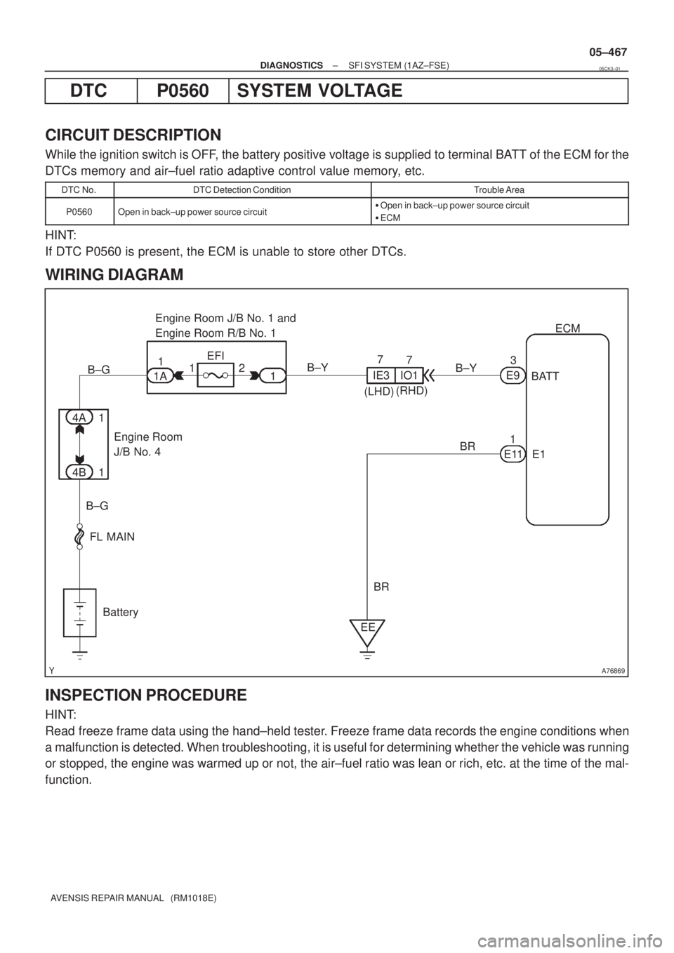
DTC P0560 SYSTEM VOLTAGE
CIRCUIT DESCRIPTION
While the ignition switch is OFF, the battery positive voltage is supplied to terminal BATT of the ECM for the
DTCs memory and air±fuel ratio adaptive control value memory, etc.
DTC No.DTC Detection ConditionTrouble Area
P0560Open in back±up power source circuit�Open in back±up power source circuit
�ECM
HINT:
If DTC P0560 is present, the ECM is unable to store other DTCs.
WIRING DIAGRAM
INSPECTION PROCEDURE
HINT:
Read freeze frame data using the hand±held tester. Freeze frame data records the engine conditions when
a malfunction is detected. When troubleshooting, it is useful for determining whether the vehicle was running
or stopped, the engine was warmed up or not, the air±fuel ratio was lean or rich, etc. at the time of the mal-
function.
05CK3±01
Page 561 of 5135

±
DIAGNOSTICS SFI SYSTEM(1AZ±FSE)
05±463
AVENSIS REPAIR MANUAL (RM1018E)
INSPECTION PROCEDURE
HINT:
Read freeze frame data using
\b�\b�
��\b� �
�\f
����reeze frame data records the engine conditions when
a malfunction is detected. When troubleshooting, it is useful for determi\
ning whether the vehicle was running
or stopped, the engine was warmed up or not, the air±fuel ratio was lea\
n or rich, etc. at the time of the mal-
function.
1CHECK OTHER DTC OUTPUT(IN ADDITION TO P0556)
(a)Read the DTC using the hand±held tester. Result :
DisplayProceed to
Only ºP0556º is output.A
ºP0556º and other DTCs are output.B
HINT:
If any other codes besides ºP0556º are output, perform the troublesh\
ooting for those DTCs first.
BGO TO RELEVANT DTC CHART(See page 05±309)
A
2 READ VALUE OF HAND±HELD TESTER(INTAKE MANIFOLD ABSOLUTE PRESSURE)
(a) Connect the hand±held tester to the DLC3.
(b) Warm up the engine.
(c) Push the hand±held tester main switch ON.
(d) Select the item ºDIAGNOSIS / OBD/MOBD / DATA LIST / ALL / MAPº and read its value displayed on
the hand±held tester with the shift lever is the ºNº position.
Standard :
ConditionIntake Manifold Absolute Pressure
Ignition switch ON (do not start engine)70 to 110 kPa (525 to 825 mmHg, 20.7 to 32.5 in.Hg)
Running without load (2,500 rpm)20 to 35 kPa (150 to 263 mmHg, 5.9 to 10.4 in.Hg)
NG Go to step 7
OK
3 READ VALUE OF HAND±HELD TESTER(STOP LIGHT SWITCH)
(a) Connect the hand±held tester to the DLC3.
(b) Turn the ignition switch ON and push the hand±held tester main switch \
ON.
(c) Select the item ºDIAGNOSIS / OBD/MOBD / DATA LIST / ALL / STOP LIGHT SWº and read its value displayed on the hand±held tester.
Result :
Brake PedalSTP Signal
DepressedON
ReleasedOFF
Page 566 of 5135

A76903
E2 (±)VC (+)
ECM Connector
E13
A76903
PB (+)E2 (±)
ECM Connector
E13
05±460
±
DIAGNOSTICS SFI SYSTEM(1AZ±FSE)
AVENSIS REPAIR MANUAL (RM1018E)
INSPECTION PROCEDURE
HINT:
�If different DTCs related to different systems that have terminal E2 as the ground terminal are output
simultaneously, terminal E2 may be open.
�Read freeze frame data using the hand±held tester. Freeze frame data records the engine conditions
when a malfunction is detected. When troubleshooting, it is useful for deter\
mining whether the vehicle
was running or stopped, the engine was warmed up or not, the air±fuel ra\
tio was lean or rich, etc. at
the time of the malfunction.
1CHECK VACUUM HOSE(BRAKE BOOSTER PRESSURE SENSOR ± BRAKE BOOSTER, INTAKE MANIFOLD ± BRAKE BOOSTER)
(a)Check that the vacuum hoses are connected correctly.
(b)Check that the vacuum hoses are not loose or disconnected.
(c)Check the vacuum hoses and tubes for clogs, cracks, holes, damage, or bl\
ockage.
NGREPAIR OR REPLACE VACUUM HOSE
OK
2INSPECT ECM(VC VOLTAGE)
(a)Turn the ignition switch ON.
(b)Measure the voltage between the specified terminals of the E13 ECM connector.
Standard:
Symbols (Terminal No.)Specified condition
VC (E13±18) ± E2 (E13±28)4.5 to 5.5 V
NGCHECK AND REPLACE ECM (See page 01±32)
OK
3 INSPECT ECM(PB VOLTAGE)
(a) Measure the voltage between the specified terminals of the E13 ECM connector.
Standard:
Symbols (Terminal No.)ConditionSpecified condition
PB (E13±26) ±
E2 (E13 28)
Ignition switch ON
(do not start engine)
0.5 to 4.5 VE2 (E13±28)Idling
0.5 to 4.5 V
NG Go to step 4
OK
CHECK FOR INTERMITTENT PROBLEMS
Page 569 of 5135

A76867
Battery 4A
ALTS13
Stop Light
Switch G±W
19
E10
FL MAIN 1AM2
1
2 (LHD)4
IGN1
DM
STP
Driver
Side J/B
1
1
2
B±G 1A
B±GB±W4
3
IE3 Engine Room
J/B No. 4
Driver
Side J/B 4B 14D1 B±G 1
2
1
B±G
B±W To Stop Light
6
I13
Ignition SW
1IE4
(RHD)
1IP1
B±R B±R B±R
2 DH
18 DA Engine
Room
R/B No. 1
and
Engine
Room
J/B No. 1
AM2 IG2
STOP22 DA
1 DN 11
R±W
(LHD) R±W
(LHD)
IR1 2
R±W
(RHD) R±W
(RHD)
IR1 3
B±W
(RHD) B±W
(RHD)
IE1 20
B±W
(LHD)B±W
(LHD)
(LHD) J9 C
(RHD) J27 E
J/C
(LHD) J8 C
(RHD) J26 AECM
12
E10 ST1± 2
DA10
DCDriver
Side J/B
IE3 6
G±W
(LHD) G±W
(LHD)
IR1 1
G±W
(RHD) G±W
(RHD)
IR1 4
G±W
(RHD)G±W
(RHD)
IE2 14
G±W
(LHD) G±W
(LHD)G±W 05±456
± DIAGNOSTICSSFI SYSTEM (1AZ±FSE)
AVENSIS REPAIR MANUAL (RM1018E)
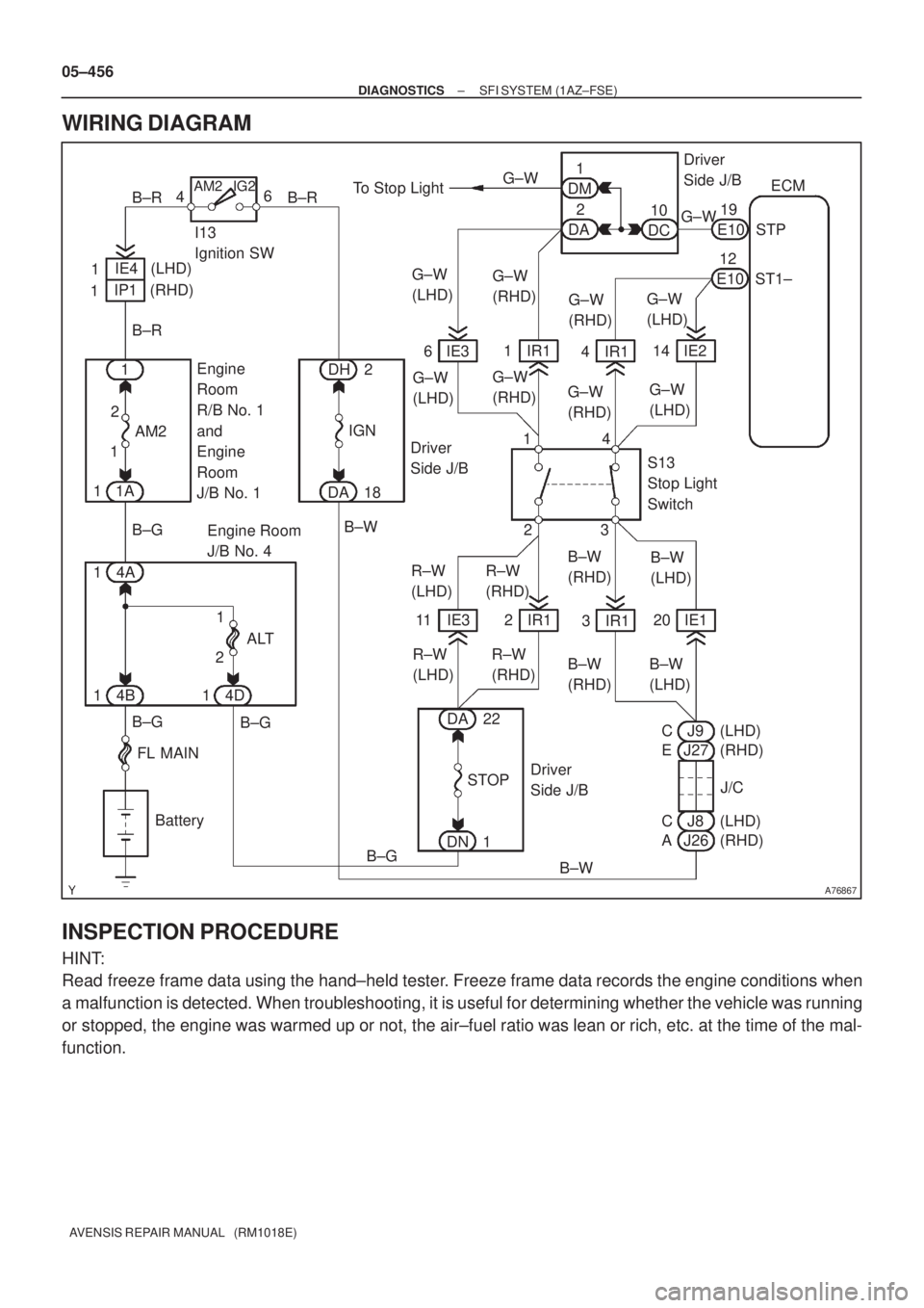
WIRING DIAGRAM
INSPECTION PROCEDURE
HINT:
Read freeze frame data using the hand±held tester. Freeze frame data records the engine conditions when
a malfunction is detected. When troubleshooting, it is useful for determining whether the vehicle was running
or stopped, the engine was warmed up or not, the air±fuel ratio was lean or rich, etc. at the time of the mal-
function.
Page 573 of 5135

A59661
E01 (±)SPD (+)
ECM Connector
E13
E10
A81704
4.5 to
5.5V
0V Turn Wheel
05±454
±
DIAGNOSTICS SFI SYSTEM(1AZ±FSE)
AVENSIS REPAIR MANUAL (RM1018E)
INSPECTION PROCEDURE
HINT:
Read freeze frame data using the hand±held tester. Freeze frame data records the engine conditions when
a malfunction is detected. When troubleshooting, it is useful for determi\
ning whether the vehicle was running
or stopped, the engine was warmed up or not, the air±fuel ratio was lea\
n or rich, etc. at the time of the mal-
function.
1CHECK OPERATION OF SPEEDOMETER
(a)Drive the vehicle and check if the operation of the speedometer in the combination meter is normal.
HINT:
The vehicle speed sensor is operating normally if the speedometer displa\
y is normal. NGCHECK SPEEDOMETER CIRCUIT (See page 05±1510)
OK
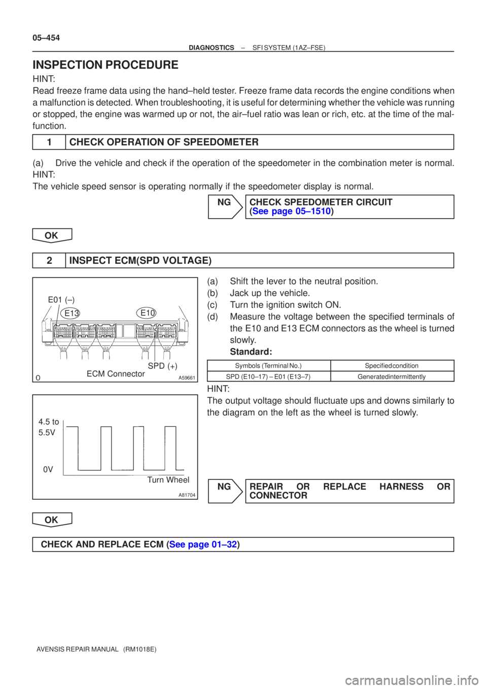
2INSPECT ECM(SPD VOLTAGE)
(a)Shift the lever to the neutral position.
(b)Jack up the vehicle.
(c)Turn the ignition switch ON.
(d)Measure the voltage between the specified terminals of the E10 and E13 ECM connectors as the wheel is turned
slowly.
Standard:
Symbols (Terminal No.)Specified condition
SPD (E10±17) ± E01 (E13±7)Generated intermittently
HINT:
The output voltage should fluctuate ups and downs similarly to
the diagram on the left as the wheel is turned slowly.
NGREPAIR OR REPLACE HARNESS OR CONNECTOR
OK
CHECK AND REPLACE ECM (See page 01±32)