Page 574 of 5135

A76875
ECM
EVP1 34
E13 EFI Relay
1 1 23
Engine Room
J/B No. 4B±W
1MREL 8
E9
Battery FL MAIN B±G2 5
GR
V5
VSV (EVAP)
2
W±G EFI No. 2 1
B±G
W±B
ECW±B
4A
14B11AEFI
1B±Y
1
2 4
4
44
4
4
B±W Engine Room
R/B No. 1
and
Engine Room
J/B No. 1Engine Room R/B No. 4
GR
B±W
EA113IE1 2
± DIAGNOSTICSSFI SYSTEM (1AZ±FSE)
05±449
AVENSIS REPAIR MANUAL (RM1018E)
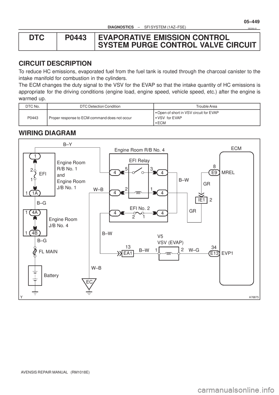
DTC P0443 EVAPORATIVE EMISSION CONTROL
SYSTEM PURGE CONTROL VALVE CIRCUIT
CIRCUIT DESCRIPTION
To reduce HC emissions, evaporated fuel from the fuel tank is routed through the charcoal canister to the
intake manifold for combustion in the cylinders.
The ECM changes the duty signal to the VSV for the EVAP so that the intake quantity of HC emissions is
appropriate for the driving conditions (engine load, engine speed, vehicle speed, etc.) after the engine is
warmed up.
DTC No.DTC Detection ConditionTrouble Area
P0443Proper response to ECM command does not occur
�Open of short in VSV circuit for EVAP
�VSV for EVAP
�ECM
WIRING DIAGRAM
05CK6±01
Page 575 of 5135

A81705
VSV is ONAirVSV is OFF
A76903
EVP1 (+)
ECM Connector
E13
E01 (±)
05±450
±
DIAGNOSTICS SFI SYSTEM(1AZ±FSE)
AVENSIS REPAIR MANUAL (RM1018E)
INSPECTION PROCEDURE
HINT:
Read freeze frame data using the hand±held tester. Freeze frame data records the engine conditions when
a malfunction is detected. When troubleshooting, it is useful for determi\
ning whether the vehicle was running
or stopped, the engine was warmed up or not, the air±fuel ratio was lea\
n or rich, etc. at the time of the mal-
function.
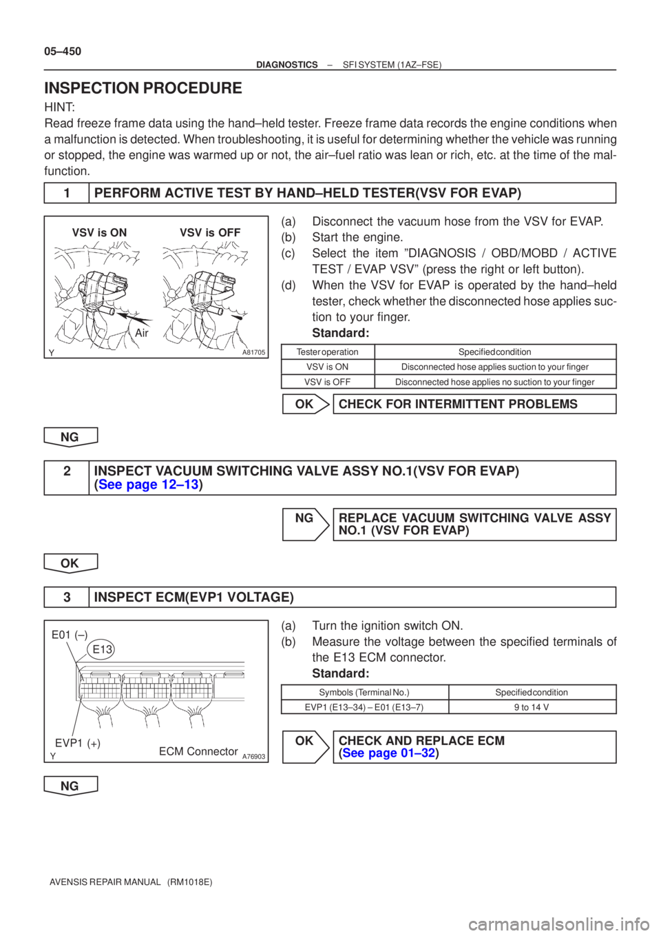
1PERFORM ACTIVE TEST BY HAND±HELD TESTER(VSV FOR EVAP)
(a)Disconnect the vacuum hose from the VSV for EVAP.
(b)Start the engine.
(c)Select the item ºDIAGNOSIS / OBD/MOBD / ACTIVE TEST / EVAP VSVº (press the right or left button).
(d)When the VSV for EVAP is operated by the hand±held tester, check whether the disconnected hose applies suc-
tion to your finger.
Standard:
Tester operationSpecified condition
VSV is ONDisconnected hose applies suction to your finger
VSV is OFFDisconnected hose applies no suction to your finger
OKCHECK FOR INTERMITTENT PROBLEMS
NG
2INSPECT VACUUM SWITCHING VALVE ASSY NO.1(VSV FOR EVAP) (See page 12±13)
NG REPLACE VACUUM SWITCHING VALVE ASSY
NO.1 (VSV FOR EVAP)
OK
3 INSPECT ECM(EVP1 VOLTAGE)
(a) Turn the ignition switch ON.
(b) Measure the voltage between the specified terminals of the E13 ECM connector.
Standard:
Symbols (Terminal No.)Specified condition
EVP1 (E13±34) ± E01 (E13±7)9 to 14 V
OK CHECK AND REPLACE ECM (See page 01±32)
NG
Page 578 of 5135

A54278
Waveform of Heated Oxygen
Sensor before CatalystNormal CatalystWaveform of Heated
Oxygen Sensor
after Catalyst
05±446
± DIAGNOSTICSSFI SYSTEM (1AZ±FSE)
AVENSIS REPAIR MANUAL (RM1018E)
DTC P0420 CATALYST SYSTEM EFFICIENCY BELOW
THRESHOLD (BANK 1)
DTC P0430 CATALYST SYSTEM EFFICIENCY BELOW
THRESHOLD (BANK 2)
CIRCUIT DESCRIPTION
The ECM compares the waveform of the heated oxygen sensor located before the catalyst with the wave-
form of the heated oxygen sensor located after the catalyst to determine whether or not the catalyst perfor-
mance has deteriorated.
The air±fuel ratio feedback compensation keeps the waveform of the heated oxygen sensor before the cata-
lyst repeatedly changing back and forth from rich to lean.
If the catalyst is functioning normally, the waveform of the heated oxygen sensor after the catalyst switches
back and forth between rich and lean much more slowly than the waveform of the heated oxygen sensor
before the catalyst.
But when both waveforms change at a similar rate, it indicates that the catalyst performance has deterio-
rated.
DTC No.DTC Detection ConditionTrouble Area
P0420
P0430
After engine and catalyst are warmed up, and while vehicle is
driven within set value and engine speed range, waveforms of
heated oxygen sensors have the same amplitude
(2 trip detection logic)�Gas leakage in exhaust system
�Heated oxygen sensor
�Three±way catalytic converter (inside exhaust manifold)
HINT:
�Bank 1 refers to the No. 1 and No. 4 cylinders.
�Bank 2 refers to the No. 2 and No. 3 cylinders.
�Sensor 1 refers to the sensor closest to the engine assembly.
�Sensor 2 refers to the sensor farthest away from the engine assembly.
05CKM±01
Page 579 of 5135

A54279
Engine Speed
2,500 to 3,000 rpm
Idling
IG SW OFF(a)
Time Warming up 3 min. or so Check (b)(c)
(d)
A54280
OX Signal Waveform (Oscilloscope)
1.0 V
0 V
0.2 sec./Division
± DIAGNOSTICSSFI SYSTEM (1AZ±FSE)
05±447
AVENSIS REPAIR MANUAL (RM1018E)
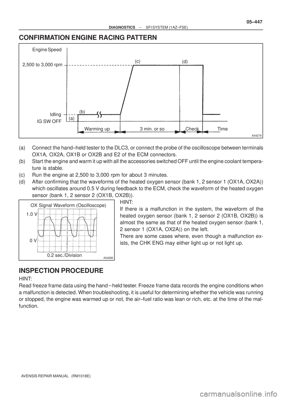
CONFIRMATION ENGINE RACING PATTERN
(a) Connect the hand±held tester to the DLC3, or connect the probe of the oscilloscope between terminals
OX1A, OX2A, OX1B or OX2B and E2 of the ECM connectors.
(b) Start the engine and warm it up with all the accessories switched OFF until the engine coolant tempera-
ture is stable.
(c) Run the engine at 2,500 to 3,000 rpm for about 3 minutes.
(d) After confirming that the waveforms of the heated oxygen sensor (bank 1, 2 sensor 1 (OX1A, OX2A))
which oscillates around 0.5 V during feedback to the ECM, check the waveform of the heated oxygen
sensor (bank 1, 2 sensor 2 (OX1B, OX2B)).
HINT:
If there is a malfunction in the system, the waveform of the
heated oxygen sensor (bank 1, 2 sensor 2 (OX1B, OX2B)) is
almost the same as that of the heated oxygen sensor (bank 1,
2 sensor 1 (OX1A, OX2A)) on the left.
There are some cases where, even though a malfunction ex-
ists, the CHK ENG may either light up or not light up.
INSPECTION PROCEDURE
HINT:
Read freeze frame data using
�� ��
���� �
��
��� �reeze frame data records the engine conditions when
a malfunction is detected. When troubleshooting, it is useful for determining whether the vehicle was running
or stopped, the engine was warmed up or not, the air±fuel ratio was lean or rich, etc. at the time of the mal-
function.
Page 584 of 5135

A76903
E1
IGF1 IGT1
IGT2
IGT3
IGT4
ECM Connector
E13
E11
GND
GND
CH1
CH2
A35500
Normal Signal Waveforms
05±442
±
DIAGNOSTICS SFI SYSTEM(1AZ±FSE)
AVENSIS REPAIR MANUAL (RM1018E)
INSPECTION PROCEDURE
HINT:
Read freeze frame data using the hand±held tester. Freeze frame data records the engine conditions when
a malfunction is detected. When troubleshooting, it is useful for determi\
ning whether the vehicle was running
or stopped, the engine was warmed up or not, the air±fuel ratio was lea\
n or rich, etc. at the time of the mal-
function.
1PERFORM SIMULATION TEST(CHECK DTC)
(a)Read the DTC and check which of the cylinders causes the DTC (See page 05±294).
(b)Clear the DTC (See page 05±294).
(c)Swap the ignition coil with igniter of the cylinder that is referred by \
the DTC for the others.
NOTICE:
Do not swap the ignition coil with igniter connector for the others.
(d)Start the engine.
(e)Read the DTC (See page 05±294). Result:
Display (DTC output)Proceed to
The same DTC is output againA
The other DTC is outputB
BREPLACE IGNITION COIL ASSY
A
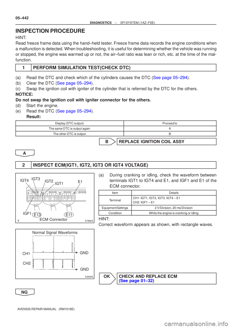
2INSPECT ECM(IGT1, IGT2, IGT3 OR IGT4 VOLTAGE)
(a)During cranking or idling, check the waveform between terminals IGT1 to IGT4 and E1, and IGF1 and E1 of the
ECM connector.
ItemDetails
TerminalCH1: IGT1, IGT2, IGT3, IGT4 ± E1
CH2: IGF1 ± E1
Equipment Settings2 V/Division, 20 ms/Division
ConditionWhile the engine is cranking or idling
HINT:
Correct waveform appears as shown, with rectangle waves.
OKCHECK AND REPLACE ECM (See page 01±32)
NG
Page 587 of 5135
±
DIAGNOSTICS SFI SYSTEM(1AZ±FSE)
05±445
AVENSIS REPAIR MANUAL (RM1018E)
NGREPAIR OR REPLACE HARNESS OR
CONNECTOR
OK
CHECK FOR FUEL PUMP CONTROL CIRCUIT (See page 05±507)
Page 588 of 5135
A76880
FL MAIN
StarterCircuit
Opening Relay
Park/Neutral
Position SWIG2 Relay
AM2
BatteryECM
STA IGSW IGN Ignition SWFuel Pump
ST2IG2
ST
Relay
(NE Signal) (A/T)FC
IG2STTr
(M/T)
(A/T) AM2
± DIAGNOSTICSSFI SYSTEM (1AZ±FSE)
05±507
AVENSIS REPAIR MANUAL (RM1018E)
FUEL PUMP CONTROL CIRCUIT
CIRCUIT DESCRIPTION
In the diagram below, when the engine is cranked, current flows from terminal ST2 of the ignition switch to
the starter relay coil and also current flows to terminal STA of ECM (STA signal).
When the STA signal and NE signal are input to the ECM, Tr is turned ON, current flows to the coil of the
circuit opening relay, the relay switches on, power is supplied to the fuel pump and the fuel pump operates.
While the NE signal is generated (engine running), the ECM keeps Tr ON (circuit opening relay ON) and the
fuel pump also keeps operating.
05CK1±01
Page 589 of 5135
A76881
IE4B±R
I13
Ignition SW
AM2
FCECM
1
B±R
6 6 4
2
IB1 Engine Room
R/B No. 1
B±G
FL MAIN
BatteryB±R
ECW±B 1ADHE9 10
IC3
32 51
1
3 5
4B 1AM2
IG2
Relay
B±G
F25
Fuel
Pump 4
5
W±B 10 Engine
Room
R/B No. 4IG2
1
24 4
4 4 4A 1C8
Circuit
Opening
Relay 16 DLIGN B±R
(LHD)IP11
(RHD)
IG2
B±R
Driver
Side J/B
B 1
11
2 2
1
Engine Room
R/B No. 4
BR B±WB±WB±WB±W
L±BG±Y G±YG±Y 05±508
± DIAGNOSTICSSFI SYSTEM (1AZ±FSE)
AVENSIS REPAIR MANUAL (RM1018E)
WIRING DIAGRAM