Page 5073 of 5135

A64023
A93668
A64026
A96570
14–16– ENGINE MECHANICALPARTIAL ENGINE ASSY (1ZZ–FE/3ZZ–FE)(From
February, 2004)
AVENSIS REPAIR MANUAL SUPPLEMENT
(RM1098E)
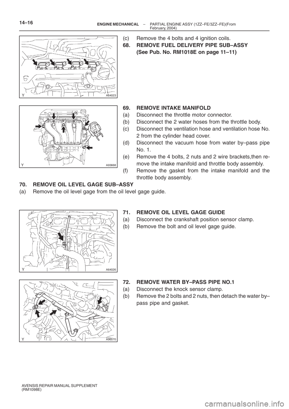
(c) Remove the 4 bolts and 4 ignition coils.
68. REMOVE FUEL DELIVERY PIPE SUB–ASSY
(See Pub. No. RM1018E on page 11–11)
69. REMOVE INTAKE MANIFOLD
(a) Disconnect the throttle motor connector.
(b) Disconnect the 2 water hoses from the throttle body.
(c) Disconnect the ventilation hose and ventilation hose No.
2 from the cylinder head cover.
(d) Disconnect the vacuum hose from water by–pass pipe
No. 1.
(e) Remove the 4 bolts, 2 nuts and 2 wire brackets,then re-
move the intake manifold and throttle body assembly.
(f) Remove the gasket from the intake manifold and the
throttle body assembly.
70. REMOVE OIL LEVEL GAGE SUB–ASSY
(a) Remove the oil level gage from the oil level gage guide.
71. REMOVE OIL LEVEL GAGE GUIDE
(a) Disconnect the crankshaft position sensor clamp.
(b) Remove the bolt and oil level gage guide.
72. REMOVE WATER BY–PASS PIPE NO.1
(a) Disconnect the knock sensor clamp.
(b) Remove the 2 bolts and 2 nuts, then detach the water by–
pass pipe and gasket.
Page 5074 of 5135
A64028
B00084
A76692
A64029
A96566
– ENGINE MECHANICALPARTIAL ENGINE ASSY (1ZZ–FE/3ZZ–FE)(From
February, 2004)14–17
AVENSIS REPAIR MANUAL SUPPLEMENT
(RM1098E)
73. REMOVE WATER INLET
(a) Remove the 2 nuts and water inlet.
74. REMOVE THERMOSTAT
75. REMOVE ENGINE OIL PRESSURE SWITCH ASSY
(See Pub. No. RM1018E on page 17–1)
76. REMOVE CAMSHAFT POSITION SENSOR
(a) Remove the bolt and camshaft position sensor.
77. REMOVE CRANKSHAFT POSITION SENSOR
(a) Remove the 2 bolts and crankshaft position sensor.
78. REMOVE KNOCK SENSOR
(a) Remove the nut and knock sensor.
79. REMOVE V–RIBBED IDLER ASSY NO.1
(a) Remove the nut, bolt, tube and idler.
Page 5075 of 5135
A64059
A64060
A76720
A76721
A76722
(a)
(b)
(b)
(b)(b) 14–18
– ENGINE MECHANICALPARTIAL ENGINE ASSY (1ZZ–FE/3ZZ–FE)(From
February, 2004)
AVENSIS REPAIR MANUAL SUPPLEMENT
(RM1098E)
80. REMOVE V–RIBBED BELT TENSIONER ASSY
(a) Remove the bolt, nut and V–ribbed belt tensioner.
81. REMOVE TRANSVERSE ENGINE ENGINE
MOUNTING BRACKET
(a) Remove the 3 bolts and transverse engine mounting
bracket.
82. REMOVE MANIFOLD STAY
(a) Remove the 3 bolts and manifold stay.
83. REMOVE MANIFOLD STAY NO.2
(a) Remove the 3 bolts and manifold stay.
84. REMOVE EXHAUST MANIFOLD HEAT INSULATOR
NO.1
(a) Disconnect the heated oxygen sensor connector.
(b) Remove the 3 bolts and nut, then remove the exhaust
manifold heat insulator.
Page 5076 of 5135
A76723
A64033
A64034
A64034
A64033
– ENGINE MECHANICALPARTIAL ENGINE ASSY (1ZZ–FE/3ZZ–FE)(From
February, 2004)14–19
AVENSIS REPAIR MANUAL SUPPLEMENT
(RM1098E)
85. REMOVE EXHAUST MANIFOLD
(a) Remove the 5 nuts, then remove the exhaust manifold
and gasket.
86. REMOVE ENGINE COOLANT TEMPERATURE
SENSOR
(a) Using SST, remove the engine coolant temperature sen-
sor.
SST 09817–33190
87. REMOVE RADIO SETTING CONDENSER
(a) Remove the bolt and condenser.
88. REMOVE WATER BY–PASS HOSE NO.2
89. REMOVE RADIATOR HOSE INLET
90. REMOVE HEATER INLET WATER HOSE
91. REPLACE PARTIAL ENGINE ASSY
92. INSTALL RADIO SETTING CONDENSER
(a) Install the condenser with the bolt.
Torque: 10 N⋅m (102 kgf⋅cm, 7 ft⋅lbf)
93. INSTALL ENGINE COOLANT TEMPERATURE
SENSOR
(a) Install a new gasket onto the engine coolant temperature
sensor.
(b) Using SST, install the engine coolant temperature sensor.
SST 09817–33190
Torque: 20 N⋅m (204 kgf⋅cm, 15 ft⋅lbf)
Page 5077 of 5135

A76723
A76722
(a)
(b)
(a)(a)
(a)
A76721
A76720
ABB
A64060
14–20– ENGINE MECHANICALPARTIAL ENGINE ASSY (1ZZ–FE/3ZZ–FE)(From
February, 2004)
AVENSIS REPAIR MANUAL SUPPLEMENT
(RM1098E)
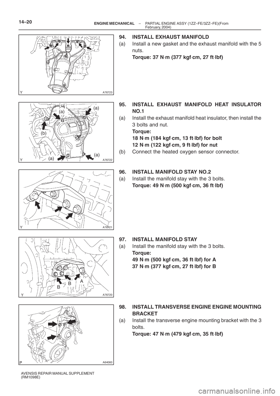
94. INSTALL EXHAUST MANIFOLD
(a) Install a new gasket and the exhaust manifold with the 5
nuts.
Torque: 37 N⋅m (377 kgf⋅cm, 27 ft⋅lbf)
95. INSTALL EXHAUST MANIFOLD HEAT INSULATOR
NO.1
(a) Install the exhaust manifold heat insulator, then install the
3 bolts and nut.
Torque:
18 N⋅m (184 kgf⋅cm, 13 ft⋅lbf) for bolt
12 N⋅m (122 kgf⋅cm, 9 ft⋅lbf) for nut
(b) Connect the heated oxygen sensor connector.
96. INSTALL MANIFOLD STAY NO.2
(a) Install the manifold stay with the 3 bolts.
Torque: 49 N⋅m (500 kgf⋅cm, 36 ft⋅lbf)
97. INSTALL MANIFOLD STAY
(a) Install the manifold stay with the 3 bolts.
Torque:
49 N⋅m (500 kgf⋅cm, 36 ft⋅lbf) for A
37 N⋅m (377 kgf⋅cm, 27 ft⋅lbf) for B
98. INSTALL TRANSVERSE ENGINE ENGINE MOUNTING
BRACKET
(a) Install the transverse engine mounting bracket with the 3
bolts.
Torque: 47 N⋅m (479 kgf⋅cm, 35 ft⋅lbf)
Page 5078 of 5135

A64059
A96566
A76692
B00084
A64028
– ENGINE MECHANICALPARTIAL ENGINE ASSY (1ZZ–FE/3ZZ–FE)(From
February, 2004)14–21
AVENSIS REPAIR MANUAL SUPPLEMENT
(RM1098E)
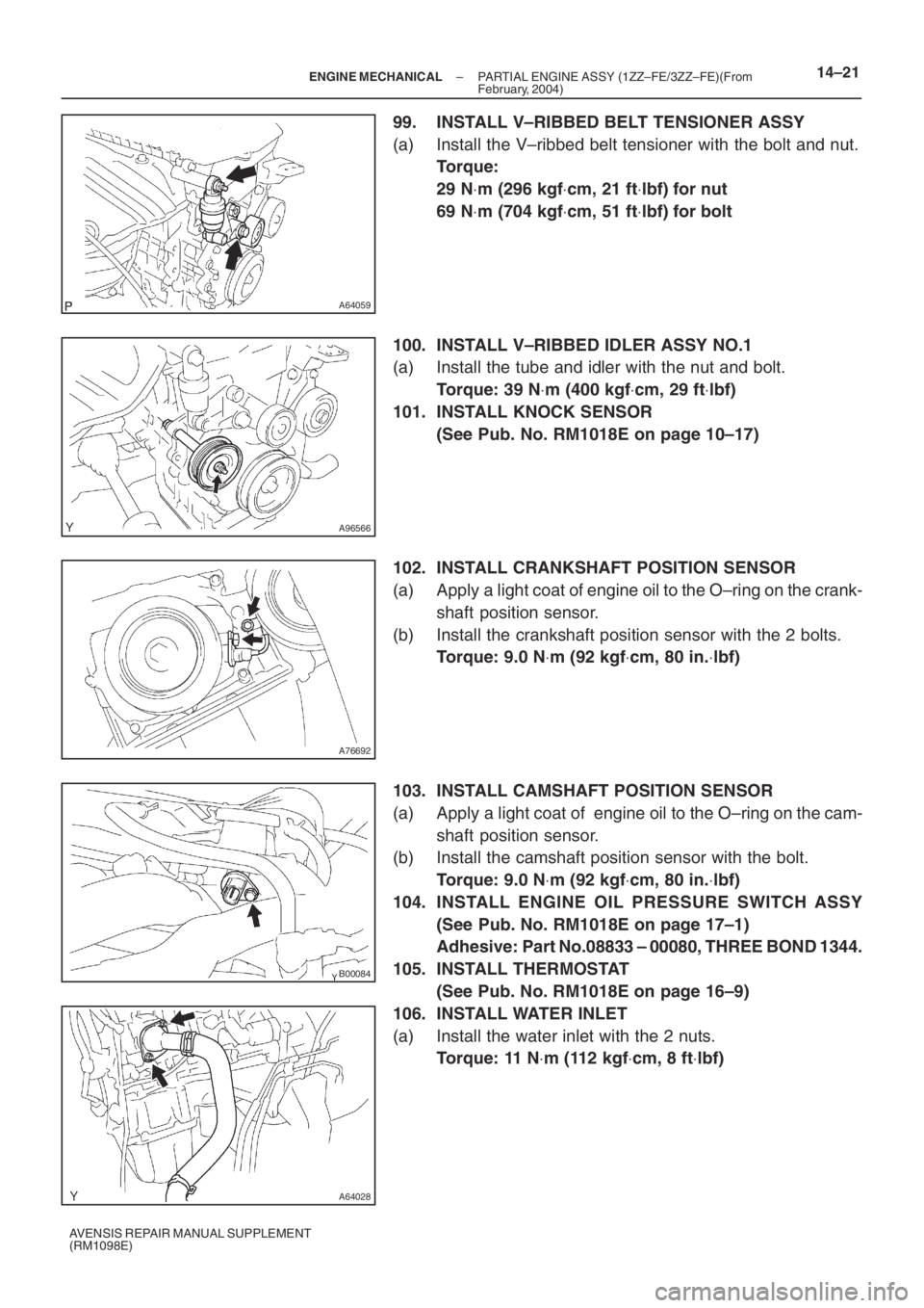
99. INSTALL V–RIBBED BELT TENSIONER ASSY
(a) Install the V–ribbed belt tensioner with the bolt and nut.
Torque:
29 N⋅m (296 kgf⋅cm, 21 ft⋅lbf) for nut
69 N⋅m (704 kgf⋅cm, 51 ft⋅lbf) for bolt
100. INSTALL V–RIBBED IDLER ASSY NO.1
(a) Install the tube and idler with the nut and bolt.
Torque: 39 N⋅m (400 kgf⋅cm, 29 ft⋅lbf)
101. INSTALL KNOCK SENSOR
(See Pub. No. RM1018E on page 10–17)
102. INSTALL CRANKSHAFT POSITION SENSOR
(a) Apply a light coat of engine oil to the O–ring on the crank-
shaft position sensor.
(b) Install the crankshaft position sensor with the 2 bolts.
Torque: 9.0 N⋅m (92 kgf⋅cm, 80 in.⋅lbf)
103. INSTALL CAMSHAFT POSITION SENSOR
(a) Apply a light coat of engine oil to the O–ring on the cam-
shaft position sensor.
(b) Install the camshaft position sensor with the bolt.
Torque: 9.0 N⋅m (92 kgf⋅cm, 80 in.⋅lbf)
104. INSTALL ENGINE OIL PRESSURE SWITCH ASSY
(See Pub. No. RM1018E on page 17–1)
Adhesive: Part No.08833 – 00080, THREE BOND 1344.
105. INSTALL THERMOSTAT
(See Pub. No. RM1018E on page 16–9)
106. INSTALL WATER INLET
(a) Install the water inlet with the 2 nuts.
Torque: 11 N⋅m (112 kgf⋅cm, 8 ft⋅lbf)
Page 5083 of 5135

A93669
14–26–
ENGINE MECHANICAL PARTIAL ENGINE ASSY (1ZZ–FE/3ZZ–FE)(From
February, 2004)
AVENSIS REPAIR MANUAL SUPPLEMENT
(RM1098E)
137. INSTALL BATTERY
Torque:
5.0 N ⋅m (51 kgf ⋅cm, 44 in. ⋅lbf) for bolt
3.5 N ⋅m (36 kgf ⋅cm, 31 in. ⋅lbf) for nut
138. INSTALL RADIATOR SUPPORT NO.1
(a) Install the 2 radiator supports with the 2 bolts.
Torque: 19 N ⋅m (194 kgf ⋅cm, 14 ft ⋅lbf)
139. INSTALL AIR CLEANER CASE SUB–ASSY
(a) Install the air cleaner case with the 3 bolts.
Torque: 5.0 N ⋅m (51 kgf ⋅cm, 44 in. ⋅lbf)
140. INSTALL AIR CLEANER ASSEMBLY WITH HOSE (See page 10–6)
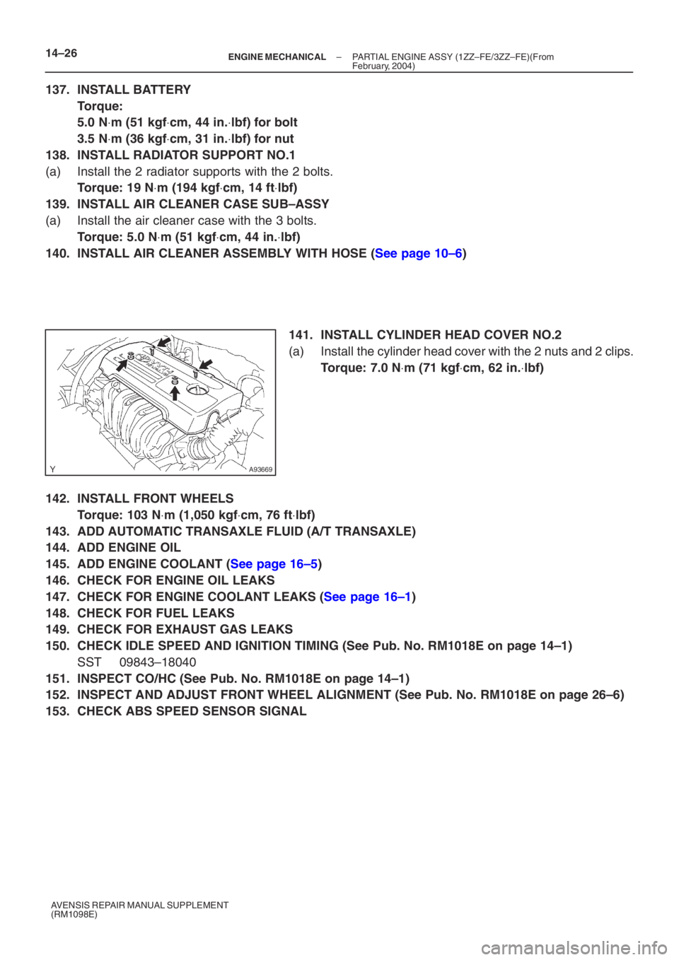
141. INSTALL CYLINDER HEAD COVER NO.2
(a) Install the cylinder head cover with the 2 nuts and 2 clips.
Torque: 7.0 N ⋅m (71 kgf ⋅cm, 62 in. ⋅lbf)
142. INSTALL FRONT WHEELS
Torque: 103 N ⋅m (1,050 kgf ⋅cm, 76 ft ⋅lbf)
143. ADD AUTOMATIC TRANSAXLE FLUID (A/T TRANSAXLE)
144. ADD ENGINE OIL
145. ADD ENGINE COOLANT (See page 16–5)
146. CHECK FOR ENGINE OIL LEAKS
147. CHECK FOR ENGINE COOLANT LEAKS (See page 16–1)
148. CHECK FOR FUEL LEAKS
149. CHECK FOR EXHAUST GAS LEAKS
150. CHECK IDLE SPEED AND IGNITION TIMING (See Pub. No. RM1018E on page 14–1)
SST 09843–18040
151. INSPECT CO/HC (See Pub. No. RM1018E on page 14–1)
152. INSPECT AND ADJUST FRONT WHEEL ALIGNMENT (See Pub. No. RM1018E on page \
26–6)
153. CHECK ABS SPEED SENSOR SIGNAL
Page 5084 of 5135
100P4–01
B66045Claw
A95570
10–12– ENGINE CONTROL SYSTEMACCELERATOR PEDAL ASSY (1ZZ–FE/3ZZ–FE)(From
February, 2004)
AVENSIS REPAIR MANUAL SUPPLEMENT
(RM1098E)
ACCELERATOR PEDAL ASSY (1ZZ–FE/3ZZ–FE)(From
February, 2004)
REPLACEMENT
1. DISCONNECT BATTERY NEGATIVE TERMINAL
2. REMOVE INSTRUMENT PANEL UNDER COVER
SUB–ASSY NO.1
(a) Remove the 2 screws.
(b) Disengage the claw and remove instrument panel under
cover sub–assembly No. 1.
3. REMOVE ACCELERATOR PEDAL ASSY
(a) Disconnect the accelerator pedal sensor connector.
(b) Remove the 2 bolts and accelerator pedal assembly.
4. INSTALL ACCELERATOR PEDAL ASSY
Torque: 5.4 N⋅m (55 kgf⋅cm, 48 in.⋅lbf)
5. INSTALL INSTRUMENT PANEL UNDER COVER SUB–ASSY NO.1
6. CONNECT BATTERY NEGATIVE TERMINAL
Torque: 5.0 N⋅m (51 kgf⋅cm, 44 in.⋅lbf)