Page 361 of 5135
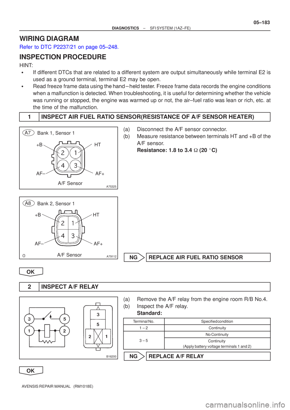
A75325
HTAF+
+B
AF±
Bank 1, Sensor 1
A7
A/F Sensor
A79112
Bank 2, Sensor 1
A8
A/F Sensor HT
AF+
+B
AF±
B16200
±
DIAGNOSTICS SFI SYSTEM(1AZ±FE)
05±183
AVENSIS REPAIR MANUAL (RM1018E)
WIRING DIAGRAM
Refer to DTC P2237/21 on page 05±248.
INSPECTION PROCEDURE
HINT:
�If different DTCs that are related to a different system are output simultaneously while terminal E2 is
used as a ground terminal, terminal E2 may be open.
�Read freeze frame data using \f�� �� ����\b� \f��\f�
� Freeze frame data records the engine conditions
when a malfunction is detected. When troubleshooting, it is useful for d\
etermining whether the vehicle
was running or stopped, the engine was warmed up or not, the air±fuel ra\
tio was lean or rich, etc. at
the time of the malfunction.
1 INSPECT AIR FUEL RATIO SENSOR(RESISTANCE OF A/F SENSOR HEATER)
(a) Disconnect the A/F sensor connector.
(b) Measure resistance between terminals HT and +B of the A/F sensor.
Resistance: 1.8 to 3.4 � (20 �C)
NG REPLACE AIR FUEL RATIO SENSOR
OK
2 INSPECT A/F RELAY
(a) Remove the A/F relay from the engine room R/B No.4.
(b) Inspect the A/F relay. Standard:
Terminal No.Specified condition
1 ± 2Continuity
No Continuity
3 ± 5Continuity
(Apply battery voltage terminals 1 and 2)
NG REPLACE A/F RELAY
OK
Page 362 of 5135
A18294
HA1A (+)HA2A (+)E04 (±)
E12
ECM Connector
E05 (±)
05±184
±
DIAGNOSTICS SFI SYSTEM(1AZ±FE)
AVENSIS REPAIR MANUAL (RM1018E)
3INSPECT ECM(VOLTAGE)
(a)Turn the ignition switch ON.
(b)Measure the voltage between the applicable terminals of the E12 ECM connectors.
Standard:
Symbols (Terminal No.)Specified condition
HA1A (E12±6) ± E04 (E12±4)9to14VHA2A (E12±5) ± E05 (E12±3)9 to 14 V
HINT:
�The HA1A means the heated oxygen sensor bank 1 sen-
sor 1.
�The HA2A means the heated oxygen sensor bank 2 sen-
sor 1.
OKCHECK AND REPLACE ECM (See page 01±32)
NG
Page 363 of 5135
����
A76787
Wire Harness Side
+B
HT
A7Bank 1 Sensor 1
A/F Sensor Connector
A79114
A8Bank 2 Sensor 1
Wire Harness Side
+B
HT
A/F Sensor Connector
A65745
HA1A HA2A
E12
ECM Connector
������A79113
Engine Room R/B No.4
A/F Relay
±
DIAGNOSTICS SFI SYSTEM(1AZ±FE)
05±185
AVENSIS REPAIR MANUAL (RM1018E)
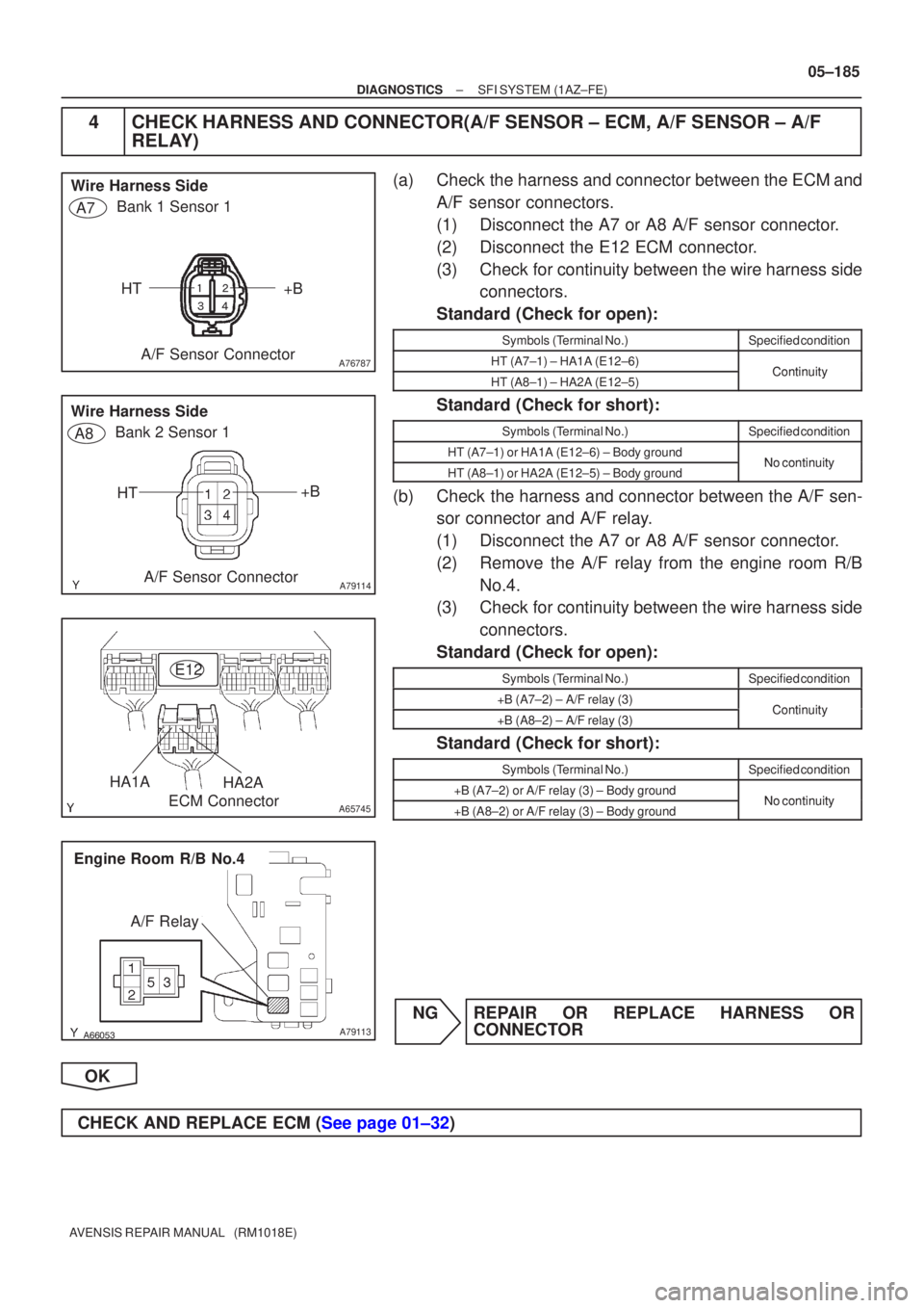
4CHECK HARNESS AND CONNECTOR(A/F SENSOR ± ECM, A/F SENSOR ± A/F
RELAY)
(a)Check the harness and connector between the ECM and
A/F sensor connectors.
(1)Disconnect the A7 or A8 A/F sensor connector.
(2)Disconnect the E12 ECM connector.
(3)Check for continuity between the wire harness sideconnectors.
Standard (Check for open):
Symbols (Terminal No.)Specified condition
HT (A7±1) ± HA1A (E12±6)ContinuityHT (A8±1) ± HA2A (E12±5)Continuity
Standard (Check for short):
Symbols (Terminal No.)Specified condition
HT (A7±1) or HA1A (E12±6) ± Body groundNocontinuityHT (A8±1) or HA2A (E12±5) ± Body groundNo continuity
(b)Check the harness and connector between the A/F sen- sor connector and A/F relay.
(1)Disconnect the A7 or A8 A/F sensor connector.
(2)Remove the A/F relay from the engine room R/B
No.4.
(3)Check for continuity between the wire harness side
connectors.
Standard (Check for open):
Symbols (Terminal No.)Specified condition
+B (A7±2) ± A/F relay (3)Continuity+B (A8±2) ± A/F relay (3)Continuity
Standard (Check for short):
Symbols (Terminal No.)Specified condition
+B (A7±2) or A/F relay (3) ± Body groundNocontinuity+B (A8±2) or A/F relay (3) ± Body groundNo continuity
NGREPAIR OR REPLACE HARNESS OR CONNECTOR
OK
CHECK AND REPLACE ECM (See page 01±32)
Page 364 of 5135
±
DIAGNOSTICS SFI SYSTEM(1AZ±FE)
05±181
AVENSIS REPAIR MANUAL (RM1018E)
DTCP0016/18CRANKSHAFT POSITION ±CAMSHAFT
POSITION CORRELATION (BANK 1 SENSOR
A)
CIRCUIT DESCRIPTION
Refer to DTC P0335/12, 13 and P0339/13 on page 05±226.
DTC No.DTC Detection ConditionTrouble Area
P0016/18Deviation in crankshaft position sensor signal and VVT sensor
1 signal (2 trip detection logic)�Mechanical system (Timing chain has jumped a tooth, chain
stretched)
� ECM
WIRING DIAGRAM
Refer to DTC P0335/12, 13 and P0339/13 on page 05±226.
INSPECTION PROCEDURE
Read freeze frame data using the hand±held tester. Freeze frame data records the engine conditions when
a malfunction is detected. When troubleshooting, it is useful for determi\
ning whether the vehicle was running
or stopped, the engine was warmed up or not, the air±fuel ratio was lea\
n or rich, etc. at the time of the mal-
function.
1CHECK VALVE TIMING (See page 14±139)
NGADJUST VALVE TIMING (See page 14±139)
OK
CHECK AND REPLACE ECM (See page 01±32)
05C7F±01
Page 365 of 5135
A71007
MassAir Flow Meter Crankshaft Position Sensor
Actual Valve TimingCorrection Target Valve Timing
Feedback
Duty Control ECM
Camshaft Timing
Oil Control
Valve (OCV)
Vehicle Speed Signal Engine Coolant Temp. SensorThrottle Position Sensor
Camshaft Position Sensor
± DIAGNOSTICSSFI SYSTEM (1AZ±FE)
05±169
AVENSIS REPAIR MANUAL (RM1018E)
DTC P0010/39 CAMSHAFT POSITION ºAº ACTUATOR
CIRCUIT (BANK 1)
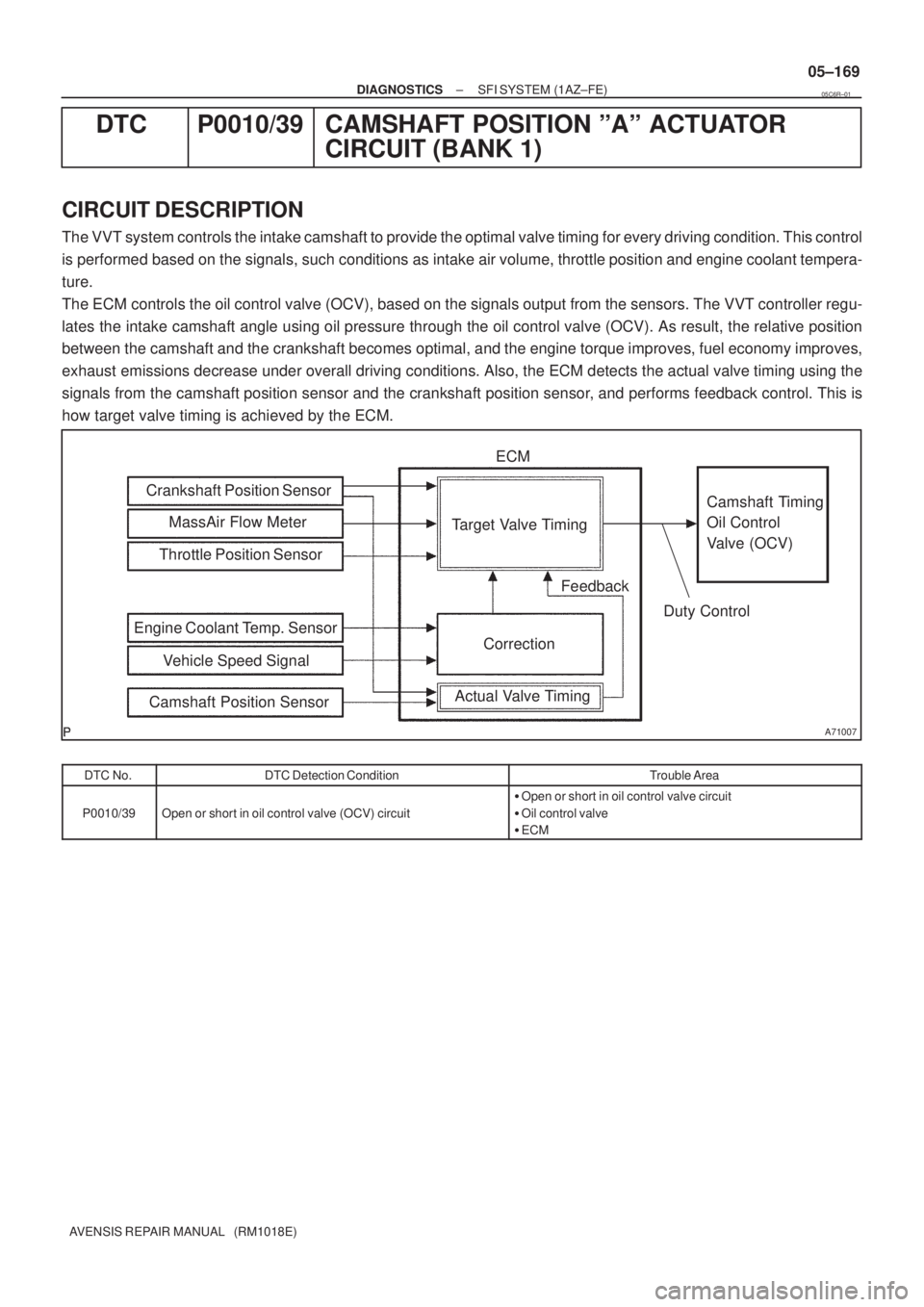
CIRCUIT DESCRIPTION
The VVT system controls the intake camshaft to provide the optimal valve timing for every driving condition. This control
is performed based on the signals, such conditions as intake air volume, throttle position and engine coolant tempera-
ture.
The ECM controls the oil control valve (OCV), based on the signals output from the sensors. The VVT controller regu-
lates the intake camshaft angle using oil pressure through the oil control valve (OCV). As result, the relative position
between the camshaft and the crankshaft becomes optimal, and the engine torque improves, fuel economy improves,
exhaust emissions decrease under overall driving conditions. Also, the ECM detects the actual valve timing using the
signals from the camshaft position sensor and the crankshaft position sensor, and performs feedback control. This is
how target valve timing is achieved by the ECM.
DTC No.DTC Detection ConditionTrouble Area
P0010/39Open or short in oil control valve (OCV) circuit
�Open or short in oil control valve circuit
�Oil control valve
�ECM
05C6R±01
Page 385 of 5135
05±248
± DIAGNOSTICSSFI SYSTEM (1AZ±FE)
AVENSIS REPAIR MANUAL (RM1018E)
DTC P2237/21 OXYGEN SENSOR PUMPING CURRENT
CIRCUIT/OPEN (FOR A/F SENSOR)(BANK 1
SENSOR 1)
DTC P2238/21 OXYGEN SENSOR PUMPING CURRENT
CIRCUIT LOW (FOR A/F SENSOR)(BANK 1
SENSOR 1)
DTC P2239/21 OXYGEN SENSOR PUMPING CURRENT
CIRCUIT HIGH (FOR A/F SENSOR)(BANK 1
SENSOR 1)
DTC P2240/28 OXYGEN SENSOR PUMPING CURRENT
CIRCUIT/OPEN (FOR A/F SENSOR)(BANK 2
SENSOR 1)
DTC P2241/28 OXYGEN SENSOR PUMPING CURRENT
CIRCUIT LOW (FOR A/F SENSOR)(BANK 2
SENSOR 1)
DTC P2242/28 OXYGEN SENSOR PUMPING CURRENT
CIRCUIT HIGH (FOR A/F SENSOR)(BANK 2
SENSOR 1)
DTC P2251/21 OXYGEN SENSOR REFERENCE GROUND
CIRCUIT/OPEN (FOR A/F SENSOR)(BANK 1
SENSOR 1)
DTC P2252/21 OXYGEN SENSOR REFERENCE GROUND
CIRCUIT LOW (FOR A/F SENSOR)(BANK 1
SENSOR 1)
DTC P2253/21 OXYGEN SENSOR REFERENCE GROUND
CIRCUIT HIGH (FOR A/F SENSOR)(BANK 1
SENSOR 1)
DTC P2254/28 OXYGEN SENSOR REFERENCE GROUND
CIRCUIT/OPEN (FOR A/F SENSOR)(BANK 2
SENSOR 1)
05C76±01
Page 386 of 5135

A73819A±A SectionAirSolid Electrolyte
(Zirconia Element)
Platinum
Electrode Heater
Exhaust Gas
Cover Element
A
A
ECM Monitored
A/F Sensor Voltage
Air±Fuel Ratio
± DIAGNOSTICSSFI SYSTEM (1AZ±FE)
05±249
AVENSIS REPAIR MANUAL (RM1018E)
DTC P2255/28 OXYGEN SENSOR REFERENCE GROUND
CIRCUIT LOW (FOR A/F SENSOR)(BANK 2
SENSOR 1)
DTC P2256/28 OXYGEN SENSOR REFERENCE GROUND
CIRCUIT HIGH (FOR A/F SENSOR)(BANK 2
SENSOR 1)
CIRCUIT DESCRIPTION
HINT:
This DTC is recorded when A/F sensor has a malfunction, although the caption is healed oxygen sensor.
The air±fuel ratio sensor are the lamination type. Compared to the conventional type, the sensor and heater
portions of the lamination type are narrower overall. Because the heat of the heater acts directly on the alumi-
na and zirconia (of the sensor portion) it accelerates the activation of the sensor.
To obtain a high purification rate of the CO, HC and NOx components of the exhaust gas, a three±way cata-
lytic converter is used. For the most efficient use of the three±way catalytic converter, the air±fuel ratio must
be precisely controlled so that it is always close to the stoichiometric air±fuel ratio.
The A/F sensor has the characteristic that it provides output voltage* being approximately proportional to
the existing air±fuel ratio. The A/F sensor output voltage* is used to provide feedback for the ECM to control
the air±fuel ratio.
By the A/F sensor output, the ECM can determine the deviation amount from the stoichiometric air±fuel ratio
and control the proper injection time immediately. If the A/F sensor is out of order, ECM is unable to perform
the accurate air±fuel ratio control.
The A/F sensor is equipped with a heater which heats the zirconia element. The heater is controlled by the
ECM. When the intake air volume is low (the temperature of the exhaust gas is low), the current flows to the
heater to heat the sensor for the accurate oxygen concentration detection.
*: The voltage value changes at the inside of the ECM only.
Page 387 of 5135
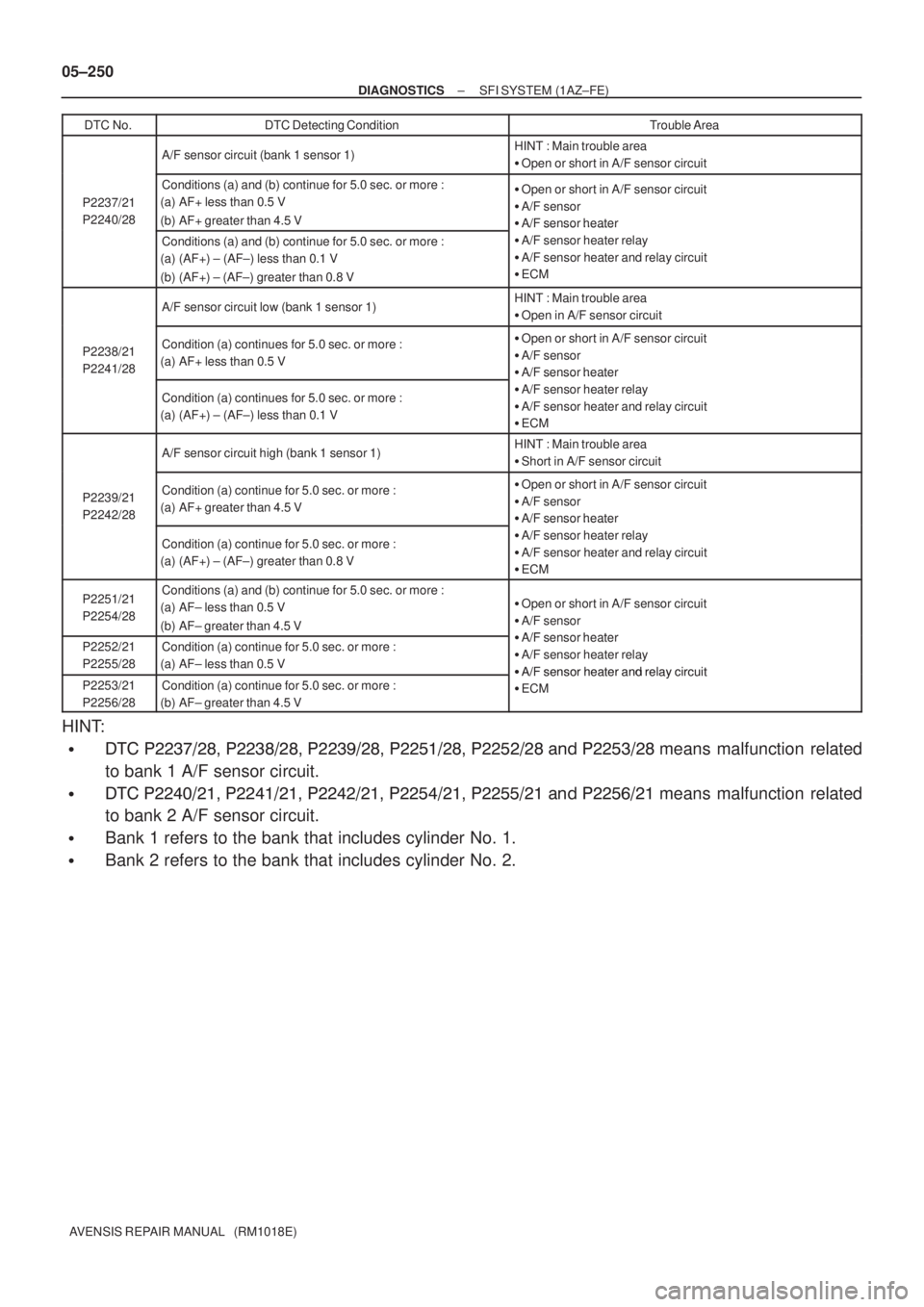
05±250
± DIAGNOSTICSSFI SYSTEM (1AZ±FE)
AVENSIS REPAIR MANUAL (RM1018E)DTC No.
DTC Detecting ConditionTrouble Area
A/F sensor circuit (bank 1 sensor 1)HINT : Main trouble area
�Open or short in A/F sensor circuit
P2237/21
P2240/28
Conditions (a) and (b) continue for 5.0 sec. or more :
(a) AF+ less than 0.5 V
(b) AF+ greater than 4.5 V�Open or short in A/F sensor circuit
�A/F sensor
�A/F sensor heater
Conditions (a) and (b) continue for 5.0 sec. or more :
(a) (AF+) ± (AF±) less than 0.1 V
(b) (AF+) ± (AF±) greater than 0.8 V
A/F sensor heater
�A/F sensor heater relay
�A/F sensor heater and relay circuit
�ECM
A/F sensor circuit low (bank 1 sensor 1)HINT : Main trouble area
�Open in A/F sensor circuit
P2238/21
P2241/28Condition (a) continues for 5.0 sec. or more :
(a) AF+ less than 0.5 V�Open or short in A/F sensor circuit
�A/F sensor
�A/F sensor heater
Condition (a) continues for 5.0 sec. or more :
(a) (AF+) ± (AF±) less than 0.1 V
A/F sensor heater
�A/F sensor heater relay
�A/F sensor heater and relay circuit
�ECM
A/F sensor circuit high (bank 1 sensor 1)HINT : Main trouble area
�Short in A/F sensor circuit
P2239/21
P2242/28Condition (a) continue for 5.0 sec. or more :
(a) AF+ greater than 4.5 V�Open or short in A/F sensor circuit
�A/F sensor
�A/F sensor heater
Condition (a) continue for 5.0 sec. or more :
(a) (AF+) ± (AF±) greater than 0.8 V
A/F sensor heater
�A/F sensor heater relay
�A/F sensor heater and relay circuit
�ECM
P2251/21
P2254/28Conditions (a) and (b) continue for 5.0 sec. or more :
(a) AF± less than 0.5 V
(b) AF± greater than 4.5 V�Open or short in A/F sensor circuit
�A/F sensor
�A/F sensor heaterP2252/21
P2255/28Condition (a) continue for 5.0 sec. or more :
(a) AF± less than 0.5 V�A/F sensor heater
�A/F sensor heater relay
�
A/F sensor heater and relay circuitP2253/21
P2256/28Condition (a) continue for 5.0 sec. or more :
(b) AF± greater than 4.5 V�A/F sensor heater and relay circuit
�ECM
HINT:
���� ��������� ��������� ����
���� ��� ����� ��� ���� ��� ��� ����means malfunction related
to bank 1 A/F sensor circuit.
���� ��������� ��������� ��������� ��� ����� ��� ��� ��� ���
���means malfunction related
to bank 2 A/F sensor circuit.
�Bank 1 refers to the bank that includes cylinder No. 1.
�Bank 2 refers to the bank that includes cylinder No. 2.