Page 388 of 5135
A76886
IE12
GRECM
MREL 8
E9
44
31
52A/F
Relay
Engine Room
R/B No.4 44
J12BR
D
J/C A/F 2
1
1A 11B±R
W±B Engine
Room
R/B No.1
Engine
Room
J/B No.1
EF ECBR J12 J/CJ13BR
D
EJ13
E B±G
Engine Room
J/B No.4 4A
4B 1 1
B±G
FL MAIN
BatteryW
W
GR
2EA11
EA1
W
W
2
4 A7
A/F Sensor
(Bank 1 Sensor 1)
1
36
E12 HA1A
23
E12 A1A+
31
E12A1A±
(*1)W
B L
A8
A/F Sensor
(Bank 2 Sensor 1)
5
E12 HA2A
22
E12 A2A+
30
E12A2A±
(*1) 2
41
3
L Y
G
*1: Shielded
± DIAGNOSTICSSFI SYSTEM (1AZ±FE)
05±251
AVENSIS REPAIR MANUAL (RM1018E)
WIRING DIAGRAM
Page 389 of 5135

05±252
± DIAGNOSTICSSFI SYSTEM (1AZ±FE)
AVENSIS REPAIR MANUAL (RM1018E)
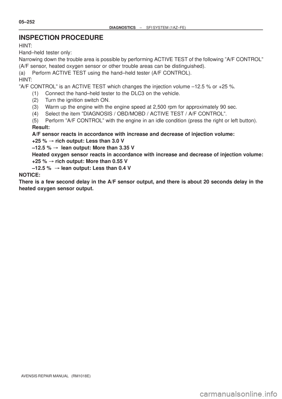
INSPECTION PROCEDURE
HINT:
Hand±held tester only:
Narrowing down the trouble area is possible by performing ACTIVE TEST of the following ºA/F CONTROLº
(A/F sensor, heated oxygen sensor or other trouble areas can be distinguished).
(a) Perform ACTIVE TEST using the hand±held tester (A/F CONTROL).
HINT:
ºA/F CONTROLº is an ACTIVE TEST which changes the injection volume ±12.5 % or +25 %.
(1) Connect the hand±held tester to the DLC3 on the vehicle.
(2) Turn the ignition switch ON.
(3) Warm up the engine with the engine speed at 2,500 rpm for approximately 90 sec.
(4) Select the item ºDIAGNOSIS / OBD/MOBD / ACTIVE TEST / A/F CONTROLº.
(5) Perform ºA/F CONTROLº with the engine in an idle condition (press the right or left button).
Result:
A/F sensor reacts in accordance with increase and decrease of injection volume:
+25 % � rich output: Less than 3.0 V
±12.5 % � lean output: More than 3.35 V
Heated oxygen sensor reacts in accordance with increase and decrease of injection volume:
+25 % � rich output: More than 0.55 V
±12.5 % � lean output: Less than 0.4 V
NOTICE:
There is a few second delay in the A/F sensor output, and there is about 20 seconds delay in the
heated oxygen sensor output.
Page 390 of 5135

+25 %
±12.5 %
More than 3.35 V
Less than 3.0 V
Case 1
Case 2
Case 3
Case 4
Output voltage of A/F sensor
(sensor 1)
Injection volume
Output voltage
Output voltage of heated oxygen
sensor (sensor 2)Mainly suspect
trouble area
OK
+25 %
±12.5 %
More than 3.35 V
Less than 3.0V
Injection volume
Output voltage
+25 %
±12.5 %
More than 0.55 V
Less than 0.4V
Injection volume
Output voltage
A/F sensor
(A/F sensor, heater, A/F sen-
sor circuit)
+25 %
±12.5 %
More than 0.55 V
Less than 0.4V
Injection volume
Output voltage
+25 %
±12.5 %
Injection volume
Output voltage
NG
+25 %
±12.5 %
Injection volume
Output voltage
NG
+25 %
±12.5 %
Injection volume
Output voltage
NG
+25 %
±12.5 %
Injection volume
Output voltage
NGExtremely rich or lean actual
air±fuel ratio
(Injector, fuel pressure, gas
leakage in exhaust system,
etc.) OK
OK
OK
No reaction
No reaction
No reaction No reaction
�
Heated oxygen sensor
(heated oxygen sensor,
heater, heated oxygen sensor
circuit)
± DIAGNOSTICSSFI SYSTEM (1AZ±FE)
05±253
AVENSIS REPAIR MANUAL (RM1018E)
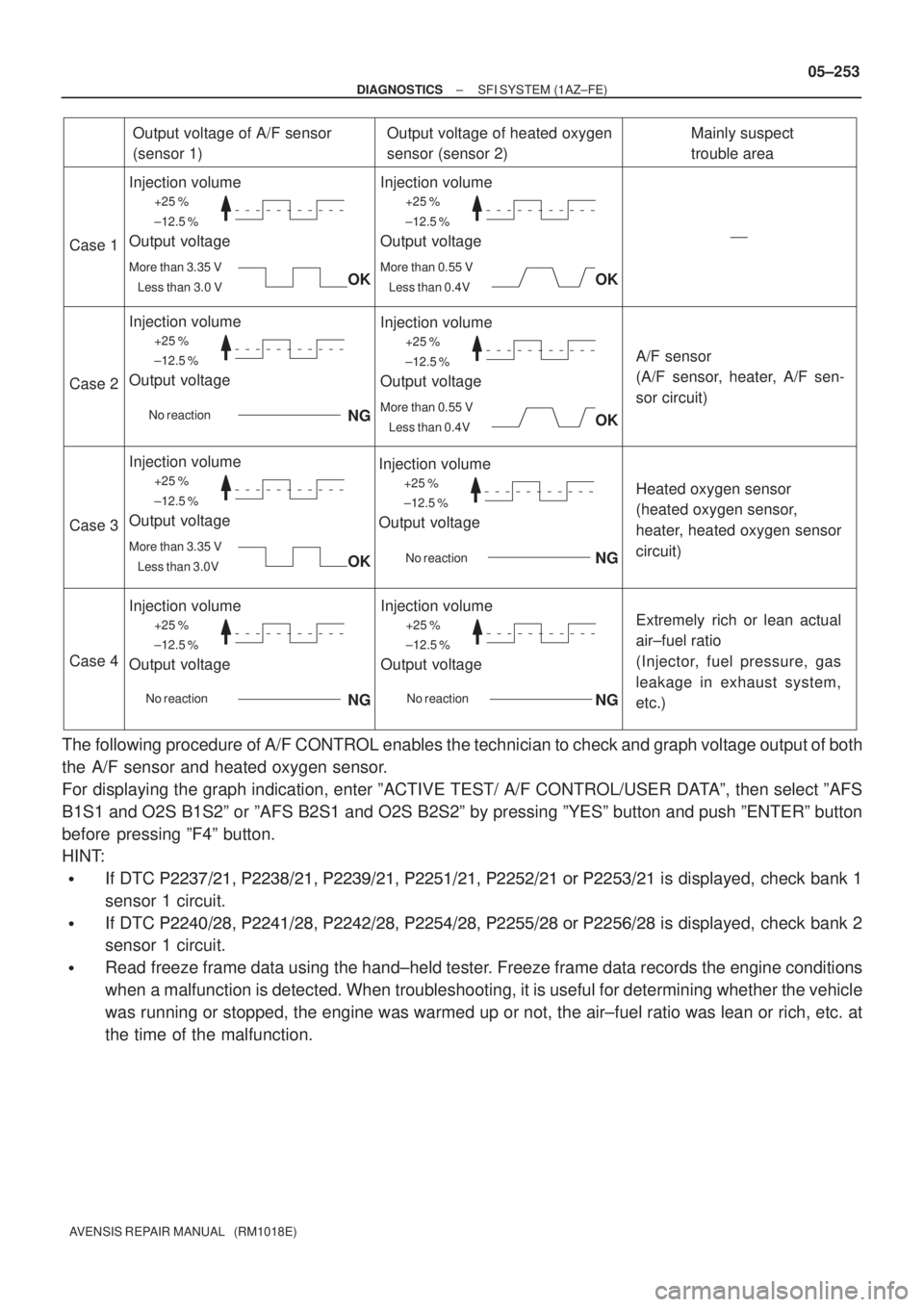
The following procedure of A/F CONTROL enables the technician to check and graph voltage output of both
the A/F sensor and heated oxygen sensor.
For displaying the graph indication, enter ºACTIVE TEST/ A/F CONTROL/USER DATAº, then select ºAFS
B1S1 and O2S B1S2º or ºAFS B2S1 and O2S B2S2º by pressing ºYESº button and push ºENTERº button
before pressing ºF4º button.
HINT:
�If DTC ��������� ��������� ����
���� ��� ����� ��� ���� �� ��� ���� is displayed, check bank 1
sensor 1 circuit.
�If DTC ��������� ��������� ��������� ��� ����� ��� ��� �� ���
��� is displayed, check bank 2
sensor 1 circuit.
�Read freeze frame data using the hand±held tester. Freeze frame data records the engine conditions
when a malfunction is detected. When troubleshooting, it is useful for determining whether the vehicle
was running or stopped, the engine was warmed up or not, the air±fuel ratio was lean or rich, etc. at
the time of the malfunction.
Page 391 of 5135
A75325
HT
AF+ +B
AF±
Bank 1, Sensor 1 A7
A/F Sensor
A79112
Bank 2, Sensor 1 A8
A/F SensorHT
AF+ +B
AF±
B16200
05±254
± DIAGNOSTICSSFI SYSTEM (1AZ±FE)
AVENSIS REPAIR MANUAL (RM1018E)
1 INSPECT AIR FUEL RATIO SENSOR(RESISTANCE OF A/F SENSOR HEATER)
(a) Disconnect the A/F sensor connector.
(b) Measure resistance between terminals HT and +B of the
A/F sensor.
Resistance: 1.8 to 3.4 � (20�C)
NG REPLACE AIR FUEL RATIO SENSOR
OK
2 INSPECT A/F RELAY
(a) Remove the A/F sensor heater relay from the engine
room R/B.
(b) Inspect the A/F senor heater relay.
Standard:
Terminal No.Specified condition
1 ± 2Continuity
No Continuity
3 ± 5Continuity
(Apply battery voltage Terminals 1 and 2)
NG REPLACE A/F RELAY
OK
Page 392 of 5135

��
��
A76787
Wire Harness Side
+B HT
A7Bank 1 Sensor 1
A/F Connector AF+
AF±
A79114
A8Bank 2 Sensor 1 Wire Harness Side
+B
HT
A/F Connector
AF+
AF±
A65745
E12
HA1AHA2AA1A±
A1A+
A2A±
A2A+
B62793
A/F Sensor A/F Relay
Heater
Sensor
A1A+ HA1A
Duty
Control ECM
From
Battery
A/F Fuse
A1A±
MREL Reference (Bank 1 Sensor 1 System Drawing)
± DIAGNOSTICSSFI SYSTEM (1AZ±FE)
05±255
AVENSIS REPAIR MANUAL (RM1018E)
3 CHECK HARNESS AND CONNECTOR(ECM ± A/F SENSOR)
(a) Disconnect the A7 or A8 A/F sensor connector.
(b) Disconnect the E12 ECM connector.
(c) Check for continuity between the wire harness side con-
nectors.
Standard (Check for open):
Symbols (Terminal No.)Specified condition
AF+ (A7±3) ± A1A+ (E12±23)
AF± (A7±4) ± A1A± (E12±31)
HT (A7±1) ± HA1A (E12±6)ContinuityAF+ (A8±3) ± A2A+ (E12±22)Continuity
AF± (A8±4) ± A2A± (E12±30)
HT (A8±1) ± HA2A (E12±5)
Standard (Check for short):
Symbols (Terminal No.)Specified condition
AF+ (A7±3) or A1A+ (E12±23) ± Body ground
AF± (A7±4) or A1A± (E12±31) ± Body ground
HT (A7±1) or HA1A (E12±6) ± Body groundNo continuityAF+ (A8±3) or A2A+ (E12±22) ± Body groundNo continuity
AF± (A8±4) or A2A± (E12±30) ± Body ground
HT (A8±1) or HA2A (E12±5) ± Body ground
Page 399 of 5135
A79413
From
Speed SensorSkid
Control
ECU4±Pulse
Combination
Meter4±Pulse
ECM 05±240
± DIAGNOSTICSSFI SYSTEM (1AZ±FE)
AVENSIS REPAIR MANUAL (RM1018E)
DTC P0500/42 VEHICLE SPEED SENSOR ºAº
CIRCUIT DESCRIPTION
The speed sensor for skid control ECU detects the wheel speed and sends the appropriate signals to the
skid control ECU.
The skid control ECU converts these signals into a 4±pulse signal and outputs it to the combination meter.
After this signal is converted into a more precise rectangular waveform by the waveform shaping circuit in-
side the combination meter, it is then transmitted to the ECM. The ECM determines the vehicle speed based
on the frequency of these pulse signals.
DTC No.DTC Detection ConditionTrouble Area
P0500/42
During the vehicle is being driven, no vehicle speed sensor
signal to the ECM
(2 trip detection logic)
�Open or short in speed sensor circuit
�Speed sensor
�Combination meter
�ECM
�Skid control ECU
05C73±01
Page 400 of 5135
A76866
Combination MeterECM
C11 V±W
SPD
17
V±W E10
J/C
18H
J10
(LHD) J20
H
(RHD) H
J10
(LHD) J20
H
(RHD)
±
DIAGNOSTICS SFI SYSTEM(1AZ±FE)
05±241
AVENSIS REPAIR MANUAL (RM1018E)
WIRING DIAGRAM
INSPECTION PROCEDURE
HINT:
Read freeze frame data using \f���� ����\b�\f��\f�
� Freeze frame data records the engine conditions when
a malfunction is detected. When troubleshooting, it is useful for determi\
ning whether the vehicle was running
or stopped, the engine was warmed up or not, the air±fuel ratio was lea\
n or rich, etc. at the time of the mal-
function.
1CHECK OPERATION OF SPEEDOMETER
(a)Drive the vehicle and check that the operation of the speedometer in the\
combination meter is normal.
HINT:
The vehicle speed sensor is operating normally if the speedometer display i\
s normal.
NGCHECK SPEEDOMETER CIRCUIT(See page 05±1500)
OK
Page 403 of 5135
A73818
Crankshaft
Position
Sensor
Camshaft
Position
Sensor
Various
SensorIGT1
IGF
IGT2
IGT3
IGT4 ECM
IgniterFrom Battery
Ignition Coil
TA C
To Tachometer
No.2 Ignition
Coil with Igniter
No.3 Ignition
Coil with Igniter
No.4 Ignition
Coil with IgniterNo.1 Ignition Coil with Igniter
Spark Plug
No.1 Cylinder
No.4 Cylinder No.2 Cylinder
No.3 Cylinder
A63956
CH1
(IGT1 to 4)
CH2
(IGF)
GND
GND
± DIAGNOSTICSSFI SYSTEM (1AZ±FE)
05±233
AVENSIS REPAIR MANUAL (RM1018E)DTC No.
DTC Detection ConditionTrouble Area
P0351/14
P0352/15
P0353/14
P0354/15
No IGF signal to ECM while engine is running
�Ignition system
�Open or short in IGF and IGT1 to 4 circuit from ignition coil
with igniter to ECM
�No. 1 to 4 ignition coil with igniter
�IG2 relay
�ECM
Reference: Inspection using the oscilloscope.
During cranking or idling, check the waveform between termi-
nals IGT1 to IGT4 and E1, and IGF and E1 of the E4 and ECM
connectors.