Page 1775 of 5135
05ADJ±04
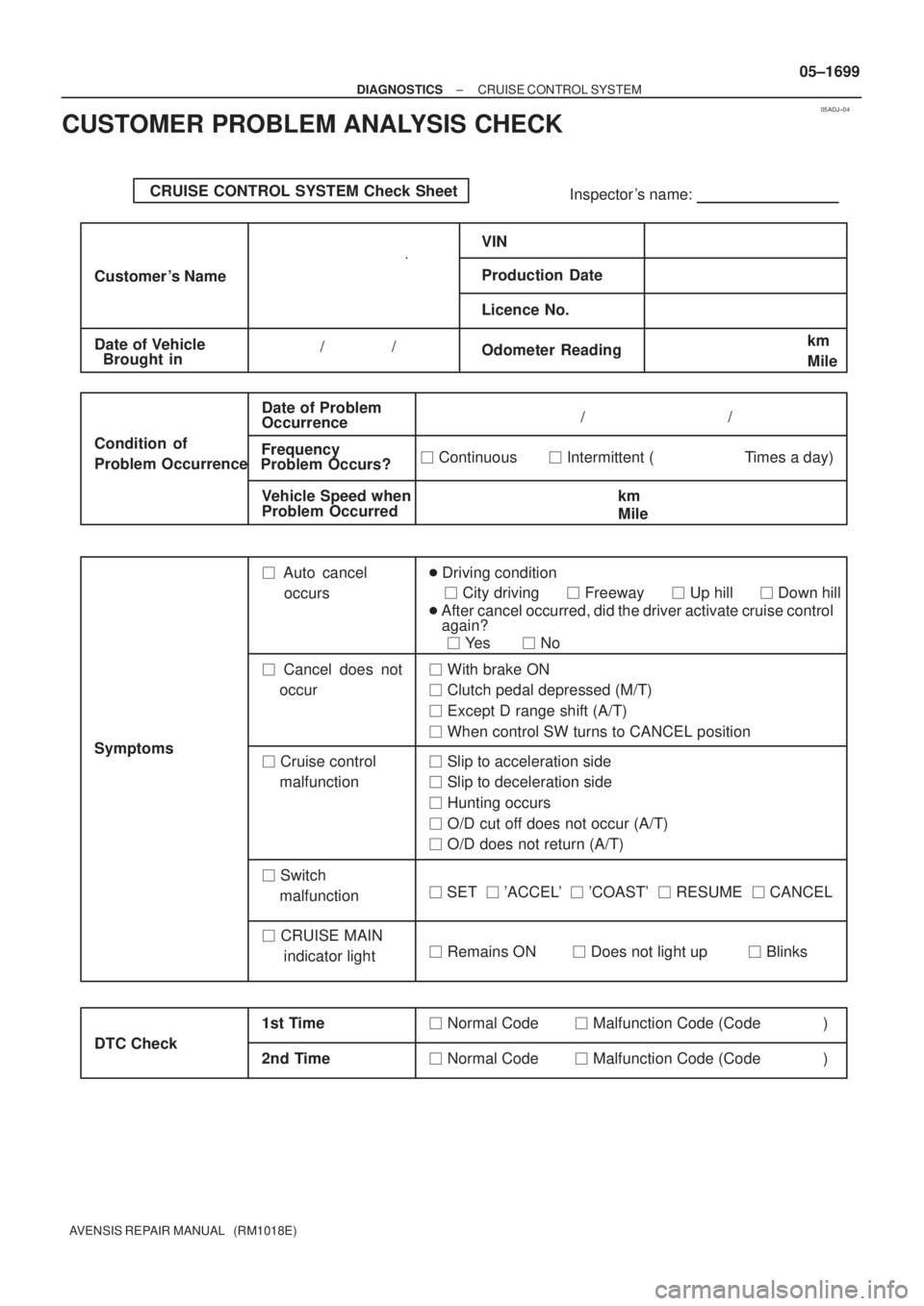
CRUISE CONTROL SYSTEM Check Sheet
Inspector 's name:
Customer 's Name
Date of VehicleVIN
Production Date
Licence No.
Odometer Reading / /km
Mile
Condition of
Problem Occurrence
Date of Problem
Frequency
Occurrence
Problem Occurs?
Vehicle Speed when
Problem Occurred / /
� Continuous � Intermittent ( Times a day)
km
Mile Brought in
� Auto cancel
occurs� Driving condition
� City driving � Freeway � Up hill � Down hill
� After cancel occurred, did the driver activate cruise control
again?
� Yes � No
� Cancel does not
occur� With brake ON
� Clutch pedal depressed (M/T)
� Except D range shift (A/T)
� When control SW turns to CANCEL position
� Cruise control
malfunction� Slip to acceleration side
� Slip to deceleration side
� Hunting occurs
� O/D cut off does not occur (A/T)
� O/D does not return (A/T)
� Switch
malfunction� SET � 'ACCEL' � 'COAST' � RESUME � CANCEL
� Remains ON � Does not light up � Blinks Symptoms
DTC Check1st Time2nd Time
� Normal Code � Malfunction Code (Code )
� Normal Code � Malfunction Code (Code ) � CRUISE MAIN
indicator light
± DIAGNOSTICSCRUISE CONTROL SYSTEM
05±1699
AVENSIS REPAIR MANUAL (RM1018E)
CUSTOMER PROBLEM ANALYSIS CHECK
Page 1843 of 5135
WRONG CORRECT
Delivery Pipe New O±ring
Injector
A51878
Delivery Pipe
O±ring
Grommet
B09613
O±ring
Retainer Pipe
Nylon Tube
Housing
A50709
A75343
Fuel Pipe Clamp No.2
A60818
SST 11±16
± FUELFUEL SYSTEM (1AZ±FE)
AVENSIS REPAIR MANUAL (RM1018E)
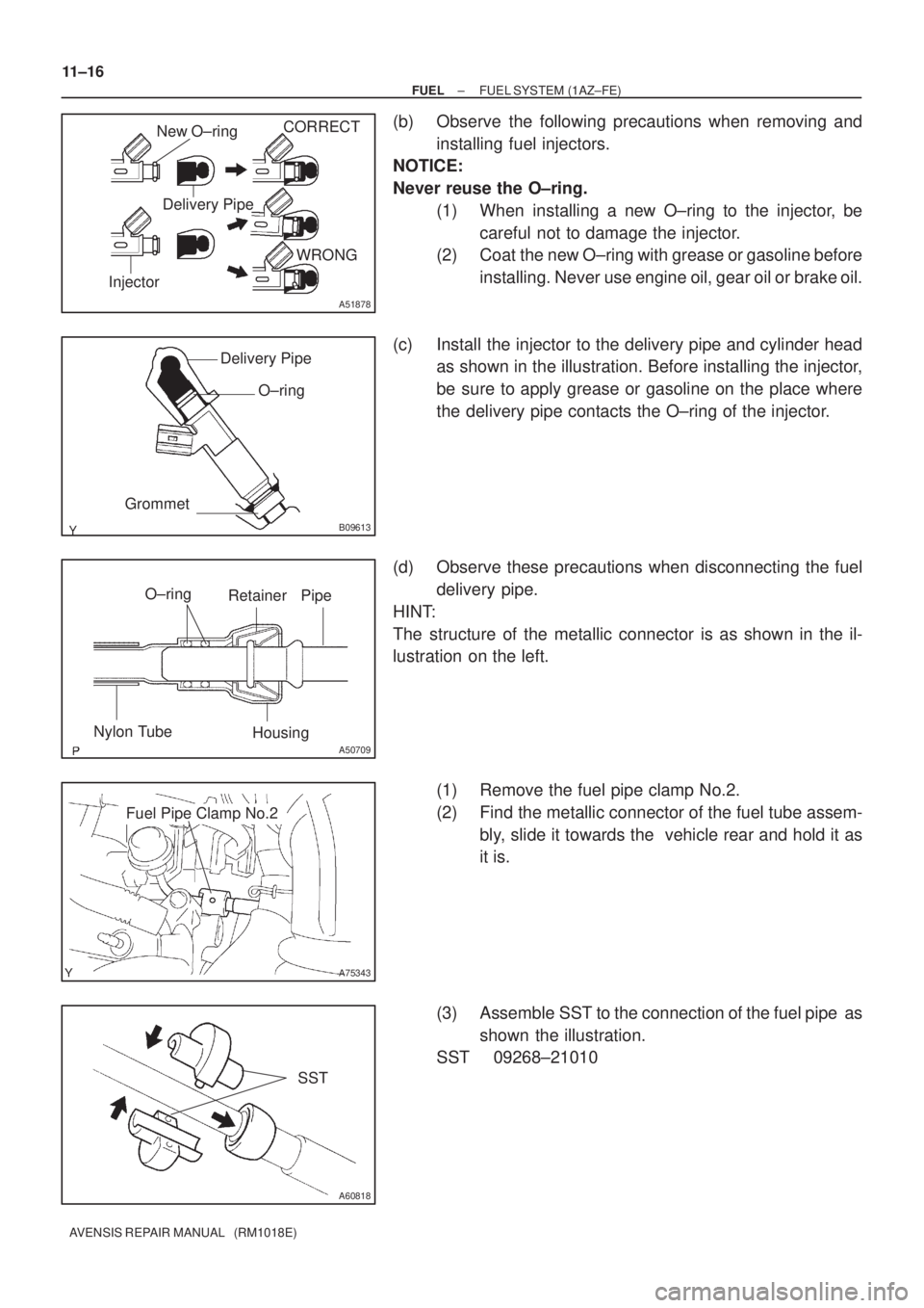
(b) Observe the following precautions when removing and
installing fuel injectors.
NOTICE:
Never reuse the O±ring.
(1) When installing a new O±ring to the injector, be
careful not to damage the injector.
(2) Coat the new O±ring with grease or gasoline before
installing. Never use engine oil, gear oil or brake oil.
(c) Install the injector to the delivery pipe and cylinder head
as shown in the illustration. Before installing the injector,
be sure to apply grease or gasoline on the place where
the delivery pipe contacts the O±ring of the injector.
(d) Observe these precautions when disconnecting the fuel
delivery pipe.
HINT:
The structure of the metallic connector is as shown in the il-
lustration on the left.
(1) Remove the fuel pipe clamp No.2.
(2) Find the metallic connector of the fuel tube assem-
bly, slide it towards the vehicle rear and hold it as
it is.
(3) Assemble SST to the connection of the fuel pipe as
shown the illustration.
SST 09268±21010
Page 1857 of 5135
O±ring
Delivery Pipe InjectorCORRECT
WRONG
B10707
A75345
Delivery Pipe
InsulatorGrommetO±ring
Insulator
Delivery Pipe
O±ring
1ZZ±FE
3ZZ±FE
O±ring
Retainer Pipe
Nylon Tube
Housing
A50709
A75344
Fuel Pipe Clamp No.2
11±2
± FUELFUEL SYSTEM (1ZZ±FE/3ZZ±FE)
AVENSIS REPAIR MANUAL (RM1018E)
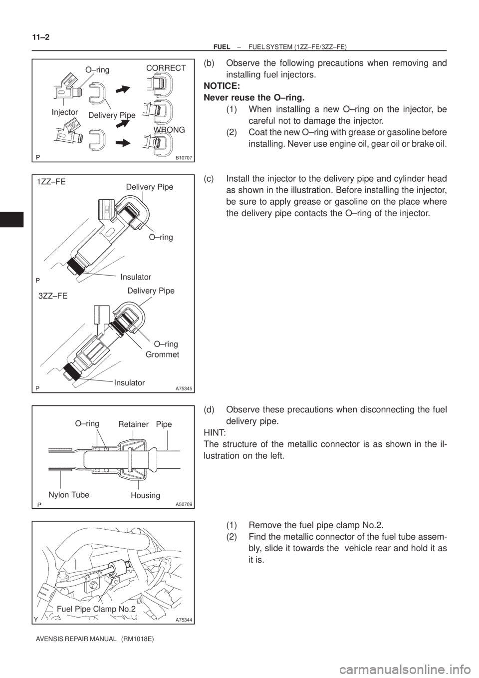
(b) Observe the following precautions when removing and
installing fuel injectors.
NOTICE:
Never reuse the O±ring.
(1) When installing a new O±ring on the injector, be
careful not to damage the injector.
(2) Coat the new O±ring with grease or gasoline before
installing. Never use engine oil, gear oil or brake oil.
(c) Install the injector to the delivery pipe and cylinder head
as shown in the illustration. Before installing the injector,
be sure to apply grease or gasoline on the place where
the delivery pipe contacts the O±ring of the injector.
(d) Observe these precautions when disconnecting the fuel
delivery pipe.
HINT:
The structure of the metallic connector is as shown in the il-
lustration on the left.
(1) Remove the fuel pipe clamp No.2.
(2) Find the metallic connector of the fuel tube assem-
bly, slide it towards the vehicle rear and hold it as
it is.
Page 1870 of 5135
110TD±01
A79578
A79579
A79580
11±42
±
FUEL FUEL INJECTOR ASSY (1AZ±FSE)
AVENSIS REPAIR MANUAL (RM1018E)
REPLACEMENT
1.DISCHARGE FUEL SYSTEM PRESSURE (See page 11±30)
2.REMOVE RADIATOR SUPPORT OPENING COVER (See page 18±16)
3.REMOVE ENGINE ROOM COVER SIDE (See page 18±17)
4.REMOVE ENGINE COVER SUB±ASSY NO.1 (See page 10±44)
5.DRAIN ENGINE COOLANT (See page 16±31)
6.REMOVE AIR CLEANER CAP SUB±ASSY (See page 10±44)
7.REMOVE THROTTLE BODY ASSY (See page 10±44)
8. REMOVE CHARCOAL CANISTER ASSY
9.REMOVE ENGINE COVER BRACKET (See page 11±52)
10.REMOVE FUEL PUMP ASSY(See page 11±52) 11. REMOVE INTAKE MANIFOLD
(a) Remove the ventilation hose No. 1.
(b) Disconnect the 2 vacuum hoses from the VSV.
(c) Disconnect the union to connector tube hose from thebrake booster assy.
(d) Remove the 5 bolts and 2 nuts from the intake manifold.
Page 1875 of 5135
A79595
42135
A79579
±
FUEL FUEL INJECTOR ASSY(1AZ±FSE)
11±47
AVENSIS REPAIR MANUAL (RM1018E)
21.INSTALL SURGE TANK STAY NO.1
(a)Install the surge tank stay No. 1 with the 3 bolts.
Torque: 21 N �m (210 kgf �cm, 15 ft �lbf)
(b)Connect the wire harness to the surge tank stay No. 1.
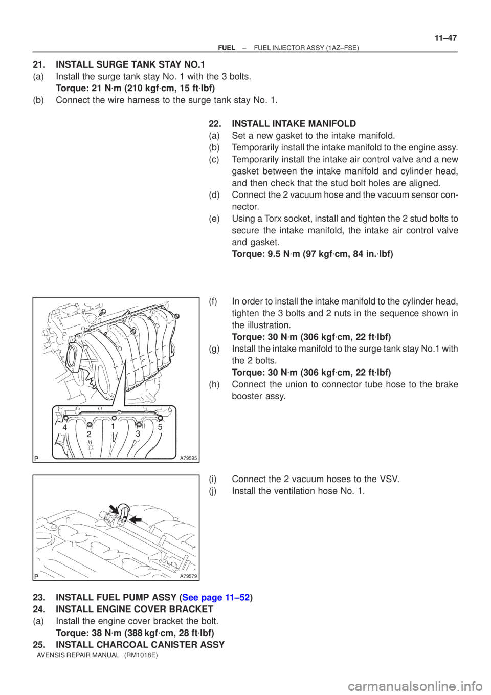
22.INSTALL INTAKE MANIFOLD
(a)Set a new gasket to the intake manifold.
(b)Temporarily install the intake manifold to the engine assy.
(c)Temporarily install the intake air control valve and a newgasket between the intake manifold and cylinder head,
and then check that the stud bolt holes are aligned.
(d)Connect the 2 vacuum hose and the vacuum sensor con-
nector.
(e)Using a Torx socket, install and tighten the 2 stud bolts to secure the intake manifold, the intake air control valve
and gasket.
Torque: 9.5 N �m (97 kgf �cm, 84 in. �lbf)
(f)In order to install the intake manifold to the cylinder head, tighten the 3 bolts and 2 nuts in the sequence shown in
the illustration.
Torque: 30 N �m (306 kgf �cm, 22 ft �lbf)
(g)Install the intake manifold to the surge tank stay No.1 with
the 2 bolts.
Torque: 30 N �m (306 kgf �cm, 22 ft �lbf)
(h)Connect the union to connector tube hose to the brake booster assy.
(i)Connect the 2 vacuum hoses to the VSV.
(j)Install the ventilation hose No. 1.
23.INSTALL FUEL PUMP ASSY (See page 11±52)
24. INSTALL ENGINE COVER BRACKET
(a) Install the engine cover bracket the bolt. Torque: 38 N �m (388 kgf �cm, 28 ft �lbf)
25. INSTALL CHARCOAL CANISTER ASSY
Page 1887 of 5135
A60083
Fuel Pipe
Clamp No.1
A
A
B12941
B12944
A82344
Vinyl Bag or plastic Bag
± FUELFUEL SYSTEM (1AZ±FSE)
11±31
AVENSIS REPAIR MANUAL (RM1018E)
(b) Observe the following precautions when removing and
installing fuel injectors.
NOTICE:
Never reuse the O±ring.
(1) When installing a new O±ring to the injector, be
careful not to damage the injector.
(2) Coat the new O±ring with grease or gasoline before
installing. Never use engine oil, gear oil or brake oil.
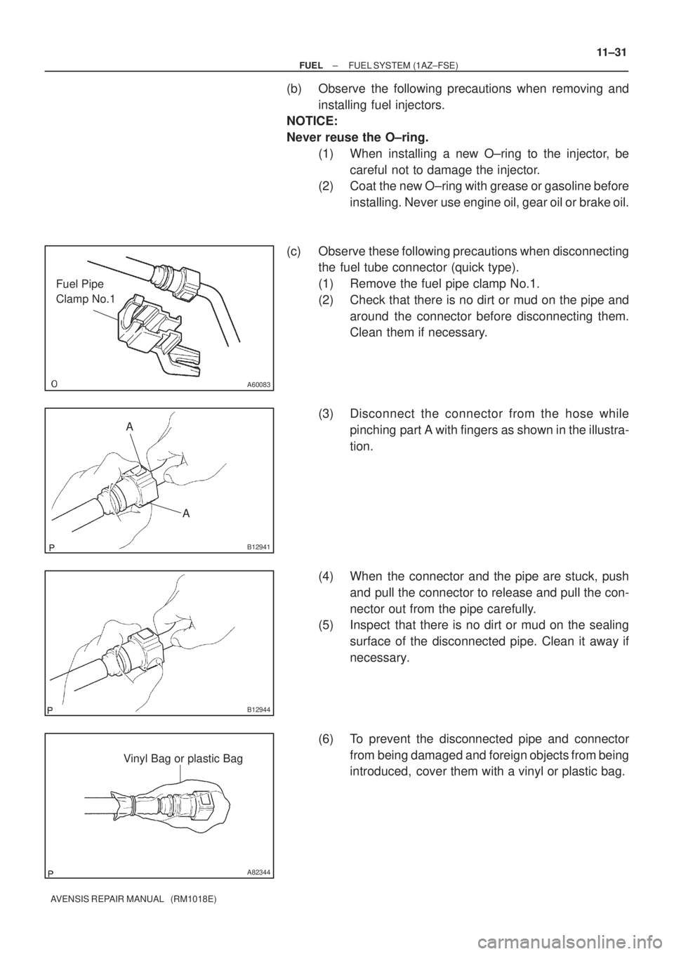
(c) Observe these following precautions when disconnecting
the fuel tube connector (quick type).
(1) Remove the fuel pipe clamp No.1.
(2) Check that there is no dirt or mud on the pipe and
around the connector before disconnecting them.
Clean them if necessary.
(3) Disconnect the connector from the hose while
pinching part A with fingers as shown in the illustra-
tion.
(4) When the connector and the pipe are stuck, push
and pull the connector to release and pull the con-
nector out from the pipe carefully.
(5) Inspect that there is no dirt or mud on the sealing
surface of the disconnected pipe. Clean it away if
necessary.
(6) To prevent the disconnected pipe and connector
from being damaged and foreign objects from being
introduced, cover them with a vinyl or plastic bag.
Page 1952 of 5135
A77884
A77885
A77886
A77887
A78450
11±106
± FUELFUEL TANK ASSY (DIESEL)
AVENSIS REPAIR MANUAL (RM1018E)
11. REMOVE PARKING BRAKE CABLE ASSY NO.2
(a) Remove the 2 set bolts of the parking brake cable.
12. REMOVE PARKING BRAKE CABLE ASSY NO.3
(a) Remove the 2 set bolts of the parking brake cable.
13. DISCONNECT BREATHER TUBE FUEL HOSE
(a) Loosen the hose clamp and disconnect the fuel tank
breather hose.
14. DISCONNECT FUEL TANK TO FILLER PIPE HOSE
(a) Loosen the hose clamp and disconnect the fuel tank to fill-
er pipe hose.
15. DISCONNECT FUEL TANK RETURN TUBE
Page 1954 of 5135
A77892
A77893
UpperFuel Tank
Rear
Hose Clamp
A81618
11±108
±
FUEL FUEL TANK ASSY(DIESEL)
AVENSIS REPAIR MANUAL (RM1018E)
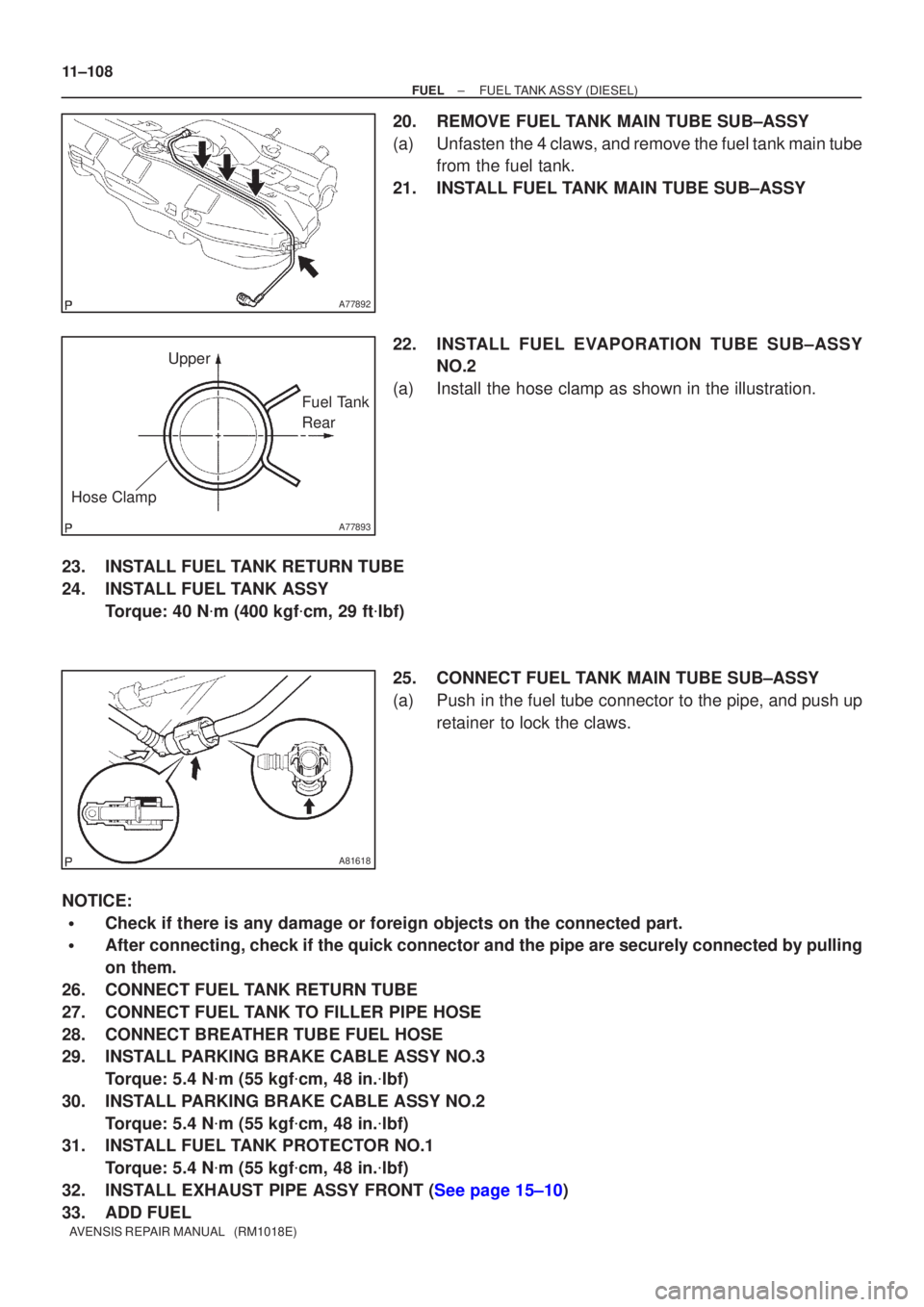
20.REMOVE FUEL TANK MAIN TUBE SUB±ASSY
(a)Unfasten the 4 claws, and remove the fuel tank main tube from the fuel tank.
21.INSTALL FUEL TANK MAIN TUBE SUB±ASSY
22.INSTALL FUEL EVAPOR ATION TUBE SUB±ASSY
NO.2
(a)Install the hose clamp as shown in the illustration.
23.INSTALL FUEL TANK RETURN TUBE
24.INSTALL FUEL TANK ASSY Torque: 40 N �m (400 kgf �cm, 29 ft �lbf)
25.CONNECT FUEL TANK MAIN TUBE SUB±ASSY
(a)Push in the fuel tube connector to the pipe, and push up retainer to lock the claws.
NOTICE:
�Check if there is any damage or foreign objects on the connected part.
�After connecting, check if the quick connector and the pipe are securely\
connected by pulling
on them.
26.CONNECT FUEL TANK RETURN TUBE
27.CONNECT FUEL TANK TO FILLER PIPE HOSE
28.CONNECT BREATHER TUBE FUEL HOSE
29.INSTALL PARKING BRAKE CABLE ASSY NO.3 Torque: 5.4 N �m (55 kgf �cm, 48 in. �lbf)
30.INSTALL PARKING BRAKE CABLE ASSY NO.2 Torque: 5.4 N �m (55 kgf �cm, 48 in. �lbf)
31.INSTALL FUEL TANK PROTECTOR NO.1
Torque: 5.4 N �m (55 kgf �cm, 48 in. �lbf)
32.INSTALL EXHAUST PIPE ASSY FRONT (See page 15±10)
33. ADD FUEL