Page 1425 of 5135
05±1404
± DIAGNOSTICSAUDIO SYSTEM
AVENSIS REPAIR MANUAL (RM1018E)
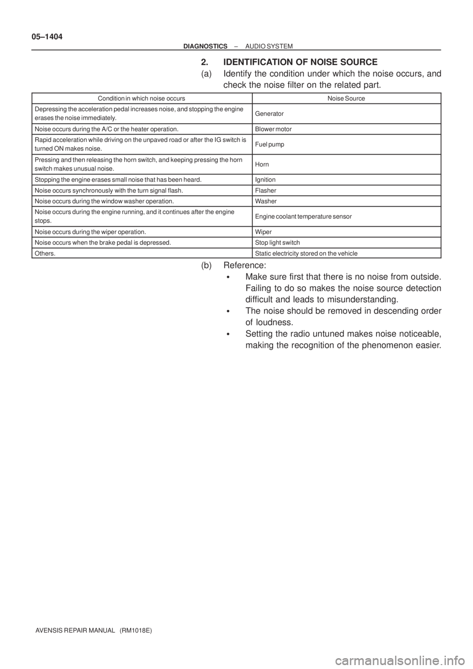
2. IDENTIFICATION OF NOISE SOURCE
(a) Identify the condition under which the noise occurs, and
check the noise filter on the related part.
Condition in which noise occursNoise Source
Depressing the acceleration pedal increases noise, and stopping the engine
erases the noise immediately.Generator
Noise occurs during the A/C or the heater operation.Blower motor
Rapid acceleration while driving on the unpaved road or after the IG switch is
turned ON makes noise.Fuel pump
Pressing and then releasing the horn switch, and keeping pressing the horn
switch makes unusual noise.Horn
Stopping the engine erases small noise that has been heard.Ignition
Noise occurs synchronously with the turn signal flash.Flasher
Noise occurs during the window washer operation.Washer
Noise occurs during the engine running, and it continues after the engine
stops.Engine coolant temperature sensor
Noise occurs during the wiper operation.Wiper
Noise occurs when the brake pedal is depressed.Stop light switch
Others.Static electricity stored on the vehicle
(b) Reference:
�Make sure first that there is no noise from outside.
Failing to do so makes the noise source detection
difficult and leads to misunderstanding.
�The noise should be removed in descending order
of loudness.
�Setting the radio untuned makes noise noticeable,
making the recognition of the phenomenon easier.
Page 1475 of 5135
± DIAGNOSTICSAUDIO SYSTEM
05±1419
AVENSIS REPAIR MANUAL (RM1018E)
NOISE OCCURS
INSPECTION PROCEDURE
1 CHECK OF SPEAKER INSTALLATION
(a) Check the speaker installation condition.
(1) Check that each speaker is securely installed.
Standard: Malfunction disappears.
HINT:
The radio is equipped with the noise prevention system that works against only the excessively large noise,
thereby excessively large noise do not occur in the radio. If large noise occurs, check whether or not the earth
on the antenna installation part and the proper noise±prevention equipment are all installed, and whether
or not the improper wiring is held.
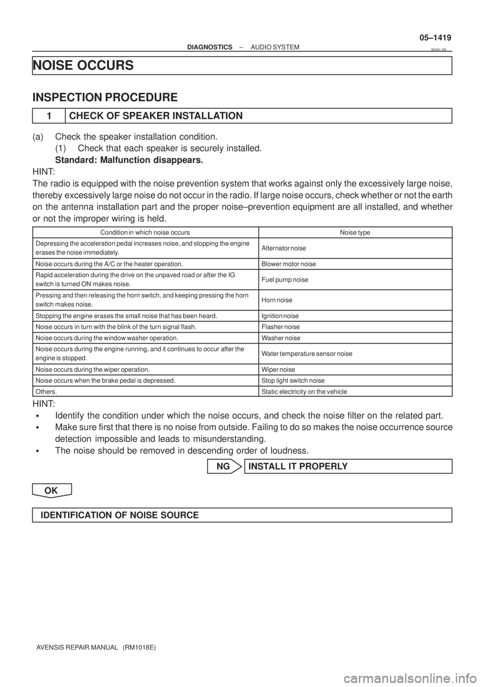
Condition in which noise occursNoise type
Depressing the acceleration pedal increases noise, and stopping the engine
erases the noise immediately.Alternator noise
Noise occurs during the A/C or the heater operation.Blower motor noise
Rapid acceleration during the drive on the unpaved road or after the IG
switch is turned ON makes noise.Fuel pump noise
Pressing and then releasing the horn switch, and keeping pressing the horn
switch makes noise.Horn noise
Stopping the engine erases the small noise that has been heard.Ignition noise
Noise occurs in turn with the blink of the turn signal flash.Flasher noise
Noise occurs during the window washer operation.Washer noise
Noise occurs during the engine running, and it continues to occur after the
engine is stopped.Water temperature sensor noise
Noise occurs during the wiper operation.Wiper noise
Noise occurs when the brake pedal is depressed.Stop light switch noise
Others.Static electricity on the vehicle
HINT:
�Identify the condition under which the noise occurs, and check the noise filter on the related part.
�Make sure first that there is no noise from outside. Failing to do so makes the noise occurrence source
detection impossible and leads to misunderstanding.
�The noise should be removed in descending order of loudness.
NG INSTALL IT PROPERLY
OK
IDENTIFICATION OF NOISE SOURCE
054A1±09
Page 1527 of 5135

05C4G±01
I35933
C10 C11
05±1506
± DIAGNOSTICSCOMBINATION METER
AVENSIS REPAIR MANUAL (RM1018E)
TERMINALS OF ECU
COMBINATION METER ASSY
Terminal No.Wiring colorConditionSpecified condition
C11±1 ± Body ground
(TURN L ± Body ground)G±W ± Body
groundTurn signal LH indicator light OFF � ONBelow 1 V �
10 to 14 V
C11±2 ± Body ground
(BRAKE LVL SW ±
Body ground)R±W ± Body
groundBrake fluid level warning switch ONBelow 1 V
C11±3 ± Body ground
(TACHO ± Body ground)GR±R ± Body
groundIgnition switch OFF � ON, Engine idle speedPuls generation (*2)
C11±5 ± Body ground
(SIGNAL EARTH ±
Body ground)W±B ± Body
groundConstantContinuity
C11±6 ± Body ground
(EMPS ± Body ground)B±W ± Body
groundIgnition switch ON and EMPS Indicator OFF � ON10 to 14 V �
Below 1 V
C11±8 ± Body ground
(AIRBAG ± Body ground)B±Y ± Body
groundIgnition switch ON and AIRBAG Indicator OFF � ON10 to 14 V �
Below 1 V
C11±9 ± Body ground
(CHECK ENGINE ±
Body ground)
W ± Body groundEngine running and CHECK ENGINE indicator OFF9 to 14 V
C11±10 ± Body ground
(AUTO LEVELING ±
Body ground)LG ± Body
groundIgnition switch ON and AUTO LEVERING Indicator OFF � ON10 to 14 V �
Below 1 V
C11±11 ± Body ground
(OIL PRESS SW ±
Body ground)Y±B ± Body
groundEngine running�StoppedNo continuity �
Continuity
C11±12 ± Body ground
(BEAM+ ± Body ground)R±W (w/HID),
R (w/o HID) ±
Body ground
Headlight OFF�ONBelow 1 V �
10 to 14 V
C11±13 ± Body ground
(TURN R ± Body ground)G±Y ± Body
groundTurn signal RH indicator light OFF � ONBelow 1 V �
10 to 14 V
C11±14 ± Body ground
(ILL+ ± Body ground)G ± Body groundCombination switch OFF�ONBelow 1 V �
10 to 14 V
C11±15 ± Body ground
(SLIP ± Body ground)LG ± Body
groundIgnition switch ON and SLIP Indicator OFF � ON10 to 14 V �
Below 1 V
C11±16 ± Body ground
(VSC ± Body ground)W±R ± Body
groundIgnition switch ON and VSC Indicator OFF � ON10 to 14 V �
Below 1 V
Page 1534 of 5135
I34627
C11±21 (IG1+)
*3:
C11±10 (AUTO LEVELING)
C11±22 (IG2+)
C11±8 (AIR BAG)
C10±8 (Rr FOG)
C10±7 (Fr FOG) BUZZER
WATER LVL
CHECK E/G
VSC
SLIP
AUTO LVL
ABS
EMPS
BRAKE
A/B ACTIVE
CIRCUIT
E/G OIL LVL
FUEL
A/T OIL TEMP
CHG
ECT SNOW
D±SEAT BELT
Rr FOG
Fr FOG
TRC OFF
OIL/P
*1: GLOW
CRUISE AIR BAG
ABS ACTIVE
CIRCUIT
EMPS ACTIVE
CIRCUIT
BRAKE ACTIVE
CIRCUIT
C11±11 (OIL PRESS SW)
C11±4 (EBD) *3: C11±6 (EMPS)C10±9 (ABS) *1, 2: C11±15 (SLIP)*1, 2: C11±16 (VSC)
C11±2 (BRAKE LVL SW)
CPU
*1: 1CD±FTV, *2: 1AZ±FSE, 2AZ±FSE, *3: 1ZZ±FE, 3ZZ±FE
C11±9 (CHECK ENGINE)
*1, 2:
C11±17 (TRC OFF) 05±1504
± DIAGNOSTICSCOMBINATION METER
AVENSIS REPAIR MANUAL (RM1018E)
Page 1535 of 5135
Terminal No.
Wire harness side
Turn Signal Flasher Relay
Skid Control ECU with Actuator Brake Fluid Level Warning Switch
Engine ECU
Oil Pressure Switch
DOME Fuse Headlight Beam Level Control ECU
Skid Control ECU with Actuator
Skid Control ECU with Actuator Turn Signal Flasher Relay Engine ECU ± Multi Display RAD No.1 Fuse
GND
EMPS ECU
TAIL Fuse
Skid Control ECU with Actuator Fuel Sensor Gauge
Skid Control ECU with Actuator
± GND
Rear Fog Light Relay Front Fog Light Relay Multi Display Fuse Filter Warning Switch (*1)
IGN Fuse Fuel Sender Gauge
Engine Oil Level Sensor Security ECU Ambient Temp. Sensor
4P OUT (Other Parts) H±HI RH Fuse/H±LP RH Fuse 1
2
3
4
5
6
7
8
9
10
11
12
13
14
15
16
17
18
19
201
2
3
4
5
6
7
8
9
10
11
12
13
14
15
16
17
18
C10
Airbag Sensor Assembly GND
GAUGE1 Fuse Skid Control ECU with Actuator
C11Engine ECU
Integration Relay
21
22
*1: 1CD±FTVAmbient Temp. Sensor
± DIAGNOSTICSCOMBINATION METER
05±1505
AVENSIS REPAIR MANUAL (RM1018E)
Page 1587 of 5135
I34628
C11±19
C 11±5
���
A05135
±
DIAGNOSTIC SCOMBIN ATIO N METER
05±15 11
A VENSIS RE PAIR MANUAL (RM1018E)
INSPECTIO N PROCEDURE
1 READ V ALUE OF HAND±HELD TESTER(SKID CONTROL ECU)
(a ) Operat e the hand±held tester according to the steps on the display and selec\
t ºD ATA LISTº.
ALL(ECM):
ItemMeasuremen t Item/
Range (Display)Normal ConditionDiagnostic Note
VEHICLE SPEEDV ehicle speed / Min.: 0 km/h,
Max.: 255 km/hAlmost same at the meter speed
(When driving)±
NG GO T O BRAKE SYSTEM
OK
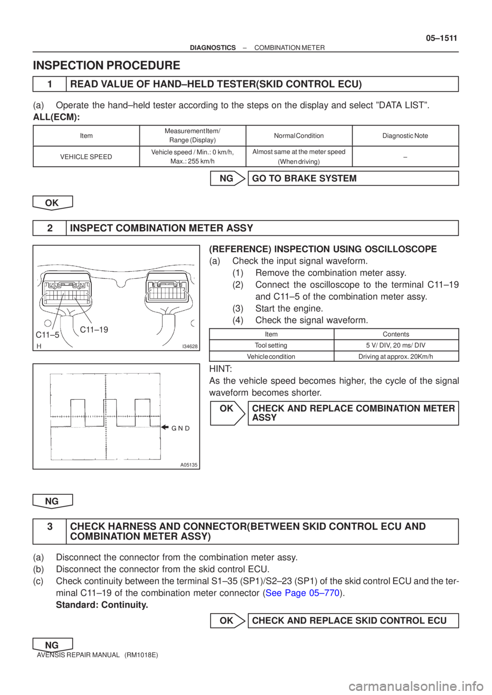
2 INSPECT COMBIN ATION METER ASSY
(REFERENCE) INSPECTION USING OSCILLOSCOPE
(a ) Check the input signal waveform.
(1 ) Remove the combination meter ass y.
(2 ) Connec t the oscilloscope to the terminal C 11±19
an d C 11±5 of the combination meter ass y.
(3 ) Start the engine.
(4 ) Check the signal waveform.
ItemContents
Too l setting5 V/ DI V, 20 ms/ DIV
V ehicle conditionDriving at approx. 20Km/h
HIN T:
A s the vehicle speed becomes highe r, the cycle of the signal
wavefor m becomes shorte r.
O K CHECK AND REPLACE COMBIN ATION METER
ASSY
NG
3 CHECK HARNESS AND CONNEC TOR(BETWEEN SKID CONTROL ECU AND
COMBIN ATION METER ASSY)
(a ) Disconnect the connector from the combination meter ass y.
(b ) Disconnect the connector from the skid control ECU.
(c ) Chec k continuity between the terminal S1±35 (SP1)/S2±23 (SP1) of th\
e skid control ECU and the ter-
mina l C 11±19 of the combination meter connector ( See Page 05±770 ).
Standard: Continuity.
OK CHECK AND REPLACE SKID CONTROL ECU
NG
Page 1758 of 5135
± DIAGNOSTICSCRUISE CONTROL SYSTEM
05±1711
AVENSIS REPAIR MANUAL (RM1018E)
DTC P0571/52 BRAKE SWITCH ºAº CIRCUIT
CIRCUIT DESCRIPTION
When the brake pedal is depressed, the stop lamp switch assy sends a signal to the ECM. When the ECM
receives this signal, it cancels the cruise control.
A fail±safe function is provided so that it functions normally, even if there is a malfunction in the stop lamp
signal circuit.
The cancel condition occurs when battery positive voltage is supplied to terminal STP.
When the brake is on, battery positive voltage is normally applied through the STOP fuse and the stop lamp
switch assy to terminal STP of the ECM, and the ECM turns the cruise control OFF.
If the harness connected to terminal STP has an open circuit, terminal STP will have battery positive voltage
and the cruise control will be turned OFF.
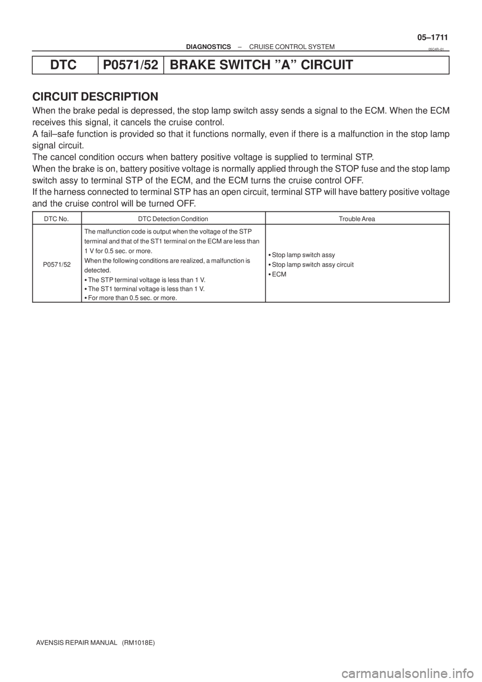
DTC No.DTC Detection ConditionTrouble Area
P0571/52
The malfunction code is output when the voltage of the STP
terminal and that of the ST1 terminal on the ECM are less than
1 V for 0.5 sec. or more.
When the following conditions are realized, a malfunction is
detected.
�The STP terminal voltage is less than 1 V.
�The ST1 terminal voltage is less than 1 V.
�For more than 0.5 sec. or more.
�Stop lamp switch assy
�Stop lamp switch assy circuit
�ECM
05C4R±01
Page 1761 of 5135
05±1714
± DIAGNOSTICSCRUISE CONTROL SYSTEM
AVENSIS REPAIR MANUAL (RM1018E)
INSPECTION PROCEDURE
HINT:
In case of using the hand±held tester, start the inspection from step1, and in case of not using the hand±held
tester, start from step 2.
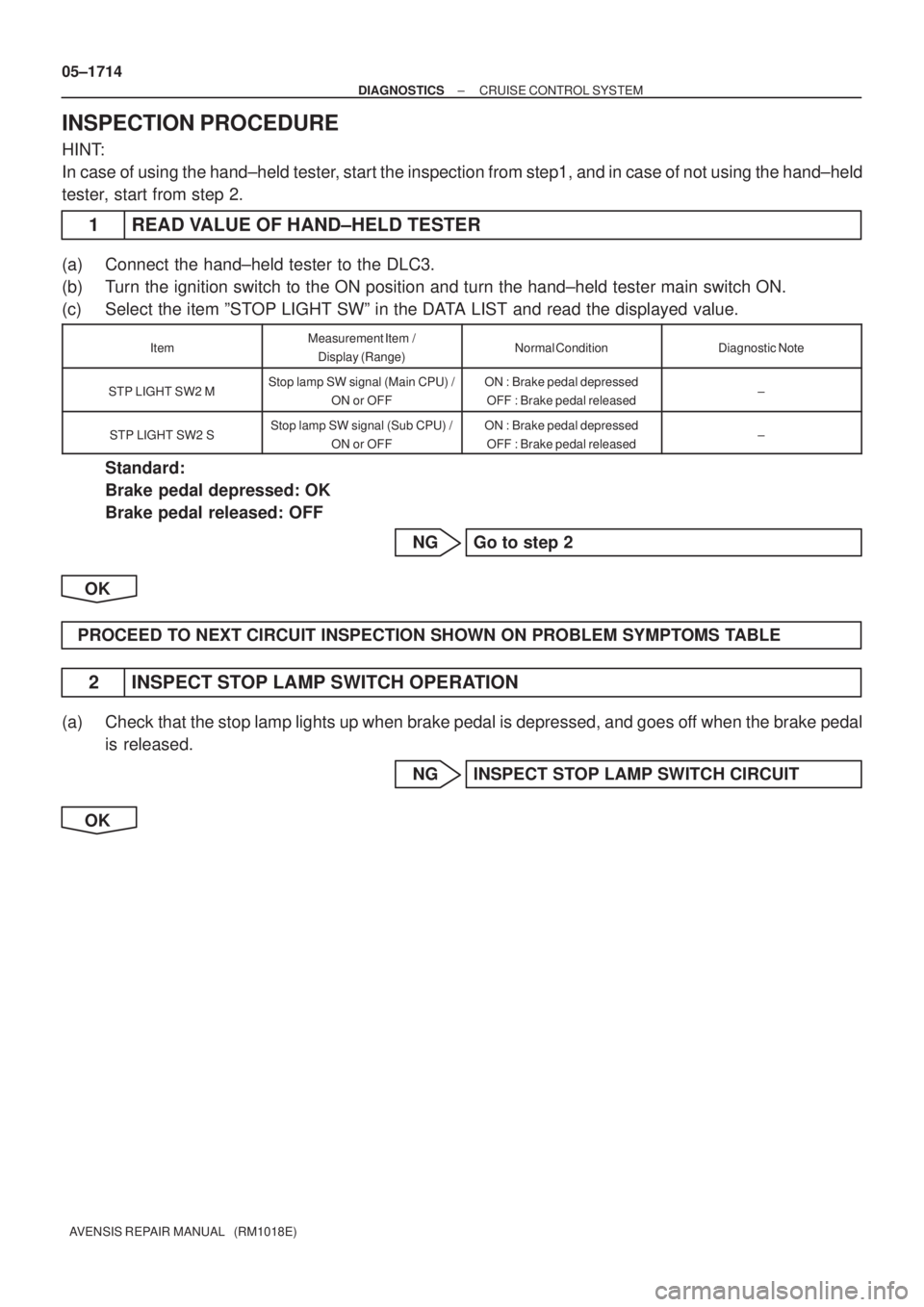
1 READ VALUE OF HAND±HELD TESTER
(a) Connect the hand±held tester to the DLC3.
(b) Turn the ignition switch to the ON position and turn the hand±held tester main switch ON.
(c) Select the item ºSTOP LIGHT SWº in the DATA LIST and read the displayed value.
ItemMeasurement Item /
Display (Range)Normal ConditionDiagnostic Note
STP LIGHT SW2 MStop lamp SW signal (Main CPU) /
ON or OFFON : Brake pedal depressed
OFF : Brake pedal released±
STP LIGHT SW2 SStop lamp SW signal (Sub CPU) /
ON or OFFON : Brake pedal depressed
OFF : Brake pedal released±
Standard:
Brake pedal depressed: OK
Brake pedal released: OFF
NG Go to step 2
OK
PROCEED TO NEXT CIRCUIT INSPECTION SHOWN ON PROBLEM SYMPTOMS TABLE
2 INSPECT STOP LAMP SWITCH OPERATION
(a) Check that the stop lamp lights up when brake pedal is depressed, and goes off when the brake pedal
is released.
NG INSPECT STOP LAMP SWITCH CIRCUIT
OK