Page 1044 of 5135
D26539
E1
ECT Solenoid
V
7L19
E12SBECM
SB 05±1030
± DIAGNOSTICSELECTRONIC CONTROLLED AUTOMATIC
TRANSAXLE [ECT] (U341E)
AVENSIS REPAIR MANUAL (RM1018E)
DTC P1798 SB SOLENOID CIRCUIT MALFUNCTION
(SHIFT SOLENOID VALVE SB)
CIRCUIT DESCRIPTION
Shift solenoid valve SB controls the 2nd brake (B1) and 1st and reverse brake pressures and performs the
1st and 2nd engine brake control.
Fail safe function:
�S shift control prohibition.
�On activating the fail±safe function during S shift, the driving mode turns to the ordinal D range.
DTC No.DTC Detection ConditionTrouble Area
P1798
ECM memorizes DTC P1798 if (a) or (b) condition below is
detected once or more.
(a) Solenoid resistance is 30 � or lower (short circuit) when
solenoid is energized.
(b) Solenoid resistance is 100 k� or higher (open circuit) when
solenoid is not energized.
�Open or short in shift solenoid valve SB circuit
�Shift solenoid valve SB
�ECM
WIRING DIAGRAM
05C8N±01
Page 1047 of 5135
D26539
E1
ECT Solenoid
Y
2R±B12
E12
STECM
ST
± DIAGNOSTICSELECTRONIC CONTROLLED AUTOMATIC
TRANSAXLE [ECT] (U341E)05±1027
AVENSIS REPAIR MANUAL (RM1018E)
DTC P1790 ST SOLENOID CIRCUIT MALFUNCTION
CIRCUIT DESCRIPTION
Shift solenoid valve ST is switched ON±OFF by a signal from ECM so that let in or out timing of O/D and
2nd brake is adjusted by operating orifice control valve. Therefore, shift solenoid valve ST operates when
letting in or out reverse clutch.
If it is broken, the shift shock becomes big.
DTC No.DTC Detection ConditionTrouble Area
P1790
ECM memorizes DTC P1790 if (a) or (b) condition below is
detected once or more.
(a) Solenoid resistance is 30 � or lower (short circuit) when
solenoid is energized.
(b) Solenoid resistance is 100 k� or higher (open circuit) when
solenoid is not energized.
�Open or short in shift solenoid valve ST circuit
�Shift solenoid valve ST
�ECM
WIRING DIAGRAM
05C8M±01
Page 1058 of 5135
05±1018±
DIAGNOSTICS ELECTRONIC CONTROLLED AUTOMATIC
TRANSAXLE [ECT](U341E)
AVENSIS REPAIR MANUAL (RM1018E)
DTCP1520STOP LIGHT SWITCH CIRCUIT MALFUNCTION
CIRCUIT DESCRIPTION
The purpose of this circuit is to prevent the engine from stalling while dr\
iving in lock±up condition, when
brakes are suddenly applied.
When the brake pedal is depressed, this switch sends signals to the ECM. Then\
the ECM cancels the opera-
tion of the lock±up clutch while braking is in progress.
DTC No.DTC Detection ConditionTrouble Area
P1520Stop light switch remains ON while vehicle running (1±trip
detection logic)�Short in stop lamp switch signal circuit
� Stop lamp switch
� ECM
WIRING DIAGRAM
See page 05±115.
INSPECTION PROCEDURE
1 INSPECT STOP LAMP SWITCH ASSY
NG REPLACE STOP LAMP SWITCH ASSY
OK
2 CHECK HARNESS AND CONNECTOR(STOP LAMP SWITCH ASSY ± ECM)
NG REPAIR OR REPLACE HARNESS OR CONNECTOR
OK
CHECK AND REPLACE ECM
05C8K±01
Page 1062 of 5135
![TOYOTA AVENSIS 2005 Service Repair Manual D30680
± DIAGNOSTICSELECTRONIC CONTROLLED AUTOMATIC
TRANSAXLE [ECT] (U341E)05±1013
AVENSIS REPAIR MANUAL (RM1018E)
DTC P0770 SHIFT SOLENOID ºEº MALFUNCTION
(SHIFT SOLENOID VALVE SL)
SYSTEM DESCR TOYOTA AVENSIS 2005 Service Repair Manual D30680
± DIAGNOSTICSELECTRONIC CONTROLLED AUTOMATIC
TRANSAXLE [ECT] (U341E)05±1013
AVENSIS REPAIR MANUAL (RM1018E)
DTC P0770 SHIFT SOLENOID ºEº MALFUNCTION
(SHIFT SOLENOID VALVE SL)
SYSTEM DESCR](/manual-img/14/57441/w960_57441-1061.png)
D30680
± DIAGNOSTICSELECTRONIC CONTROLLED AUTOMATIC
TRANSAXLE [ECT] (U341E)05±1013
AVENSIS REPAIR MANUAL (RM1018E)
DTC P0770 SHIFT SOLENOID ºEº MALFUNCTION
(SHIFT SOLENOID VALVE SL)
SYSTEM DESCRIPTION
The ECM uses the signals from the throttle position sensor, air±flow meter and crankshaft position sensor
to monitor the engagement condition of the lock±up clutch.
Then the ECM compares the engagement condition of the lock±up clutch with the lock±up schedule in the
ECM memory to detect mechanical trouble of the shift solenoid valve SL, valve body and torque converter
clutch or automatic transaxle (clutch, brake or gear etc.).
DTC No.DTC Detecting ConditionTrouble Area
P0770
�Lock±up does not occur when driving in the lock±up range
(normal driving at 80 km/h �50 mph�), or lock±up remains ON
in the lock±up OFF range.
(2±trip detection logic)
�When lock±up is ON, clutch or brake slips or gear is broken.
(2±trip detection logic)�Shift solenoid valve SL is stuck open or closed
�Valve body blocked or stuck
�Shift solenoid valve SL
�Torque converter clutch
�Automatic transaxle (clutch, brake or gear etc.)
INSPECTION PROCEDURE
1 INSPECT SHIFT SOLENOID VALVE(SL)
(a) Remove the shift solenoid valve SL.
(b) Measure the resistance between terminal SL of shift sole-
noid valve and the solenoid valve body.
OK:
Resistance: 11 to 15 � at 20�C (68�F)
(c) Connect the positive (+) lead to the terminal of solenoid
valve connector and the negative (±) lead to the solenoid
valve body.
OK:
The solenoid valve makes an operating noise.
NG REPLACE SHIFT SOLENOID VALVE(SL)
OK
2 INSPECT TRANSMISSION VALVE BODY ASSY(See chapter 2 in the problem
symptoms table)
NG REPAIR OR REPLACE TRANSMISSION VALVE
BODY ASSY
OK
05C8J±01
Page 1067 of 5135
![TOYOTA AVENSIS 2005 Service Repair Manual ± DIAGNOSTICSELECTRONIC CONTROLLED AUTOMATIC
TRANSAXLE [ECT] (U341E)05±1007
AVENSIS REPAIR MANUAL (RM1018E)
DTC P0750 SHIFT SOLENOID ºAº MALFUNCTION
(SHIFT SOLENOID VALVE S1)
DTC P0755 SHIFT SOL TOYOTA AVENSIS 2005 Service Repair Manual ± DIAGNOSTICSELECTRONIC CONTROLLED AUTOMATIC
TRANSAXLE [ECT] (U341E)05±1007
AVENSIS REPAIR MANUAL (RM1018E)
DTC P0750 SHIFT SOLENOID ºAº MALFUNCTION
(SHIFT SOLENOID VALVE S1)
DTC P0755 SHIFT SOL](/manual-img/14/57441/w960_57441-1066.png)
± DIAGNOSTICSELECTRONIC CONTROLLED AUTOMATIC
TRANSAXLE [ECT] (U341E)05±1007
AVENSIS REPAIR MANUAL (RM1018E)
DTC P0750 SHIFT SOLENOID ºAº MALFUNCTION
(SHIFT SOLENOID VALVE S1)
DTC P0755 SHIFT SOLENOID ºBº MALFUNCTION
(SHIFT SOLENOID VALVE S2)
SYSTEM DESCRIPTION
The ECM uses signals from the vehicle speed sensor and speed sensor NT to detect the actual gear position
(1st, 2nd, 3rd or O/D gear).
Then the ECM compares the actual gear with the shift schedule in the ECM memory to detect the mechanical
trouble of the shift solenoid valves, the valve body or automatic transaxle (clutch, brake or gear etc.).
DTC No.DTC Detecting ConditionTrouble Area
P0750
The gear required by the ECM does not match the actual gear
�Shift solenoid valve S1 is stuck open or closed
�Valve body is blocked up or stuck
�Automatic transaxle (clutch, brake or gear etc.)
P0755
The gear required by the ECM does not match the actual gear
when driving (2±trip detection logic)�Shift solenoid valve S2 is stuck open or closed
�Valve body is blocked up or stuck
�Automatic transaxle (clutch, brake or gear etc.)
05C8H±01
Page 1076 of 5135

AVENSIS REPAIR MANUAL (RM1018E)
Chapter 3: Off±vehicle Repair
( � : U340E, U341E AUTOMATIC TRANSAXLE Repair Manual Pub. TOYOTA AVENSIS 2005 Service Repair Manual 05±1002±
DIAGNOSTICS ELECTRONIC CONTROLLED AUTOMATIC
TRANSAXLE [ECT](U341E)
AVENSIS REPAIR MANUAL (RM1018E)
Chapter 3: Off±vehicle Repair
( � : U340E, U341E AUTOMATIC TRANSAXLE Repair Manual Pub.](/manual-img/14/57441/w960_57441-1075.png)
05±1002±
DIAGNOSTICS ELECTRONIC CONTROLLED AUTOMATIC
TRANSAXLE [ECT](U341E)
AVENSIS REPAIR MANUAL (RM1018E)
Chapter 3: Off±vehicle Repair
( � : U340E, U341E AUTOMATIC TRANSAXLE Repair Manual Pub. No. RM824E)
SymptomSuspect AreaSee page
Vehicle does not move in any forward range and reverse range
1. Planetary gear unit
2. Forward clutch
3. One±way clutch No.2
4. Reverse Clutch
5. 1st and reverse brake�
�
�
�
�
Vehicle does not move in R range
1. Planetary gear unit
2. Reverse Clutch
3. 1st and reverse brake�
�
�
No up±shift (1st � 2nd)1. 2nd brake
2. One±way clutch No.1�
�
No up±shift (2nd � 3rd)Direct clutch�
No up±shift (3rd � O/D)O/D and 2nd brake�
No lock±up or No lock±up offTorque converter clutch40±37
Harsh engagement (N � D)1. Forward clutch
2. One±way clutch No.2�
�
Harsh engagement (N � R)1. Reverse clutch
2. 1st and reverse brake�
�
Harsh engagement (Lock±up)Torque converter clutch40±37
Harsh engagement (1st � 2nd)1. 2nd brake
2. One±way clutch No.1�
�
Harsh engagement (2nd � 3rd)Direct clutch�
Harsh engagement (3rd � O/D)O/D and 2nd brake�
Slip or shudder (Forward range)
1. Torque converter clutch
2. Forward clutch
3. Direct clutch
4. O/D and 2nd brake
5. 2nd brake
6. One±way clutch No.1
7. One±way clutch No.240±37
�
�
�
�
�
�
Slip or shudder (Reverse range)1. Reverse clutch
2. 1st and reverse brake�
�
Slip or shudder (1st)One±way clutch No.2�
Slip or shudder (2nd)1. 2nd brake
2. One±way clutch No.1�
�
Slip or shudder (3rd)Direct clutch�
Slip or shudder (O/D)O/D and 2nd brake�
No engine braking (1st)1st and reverse brake�
No engine braking (2nd)O/D and 2nd brake�
Poor acceleration (All range)Torque converter clutch40±37
Large shift shock or engine stalls when starting off or stoppingTorque converter clutch40±37
Page 1137 of 5135

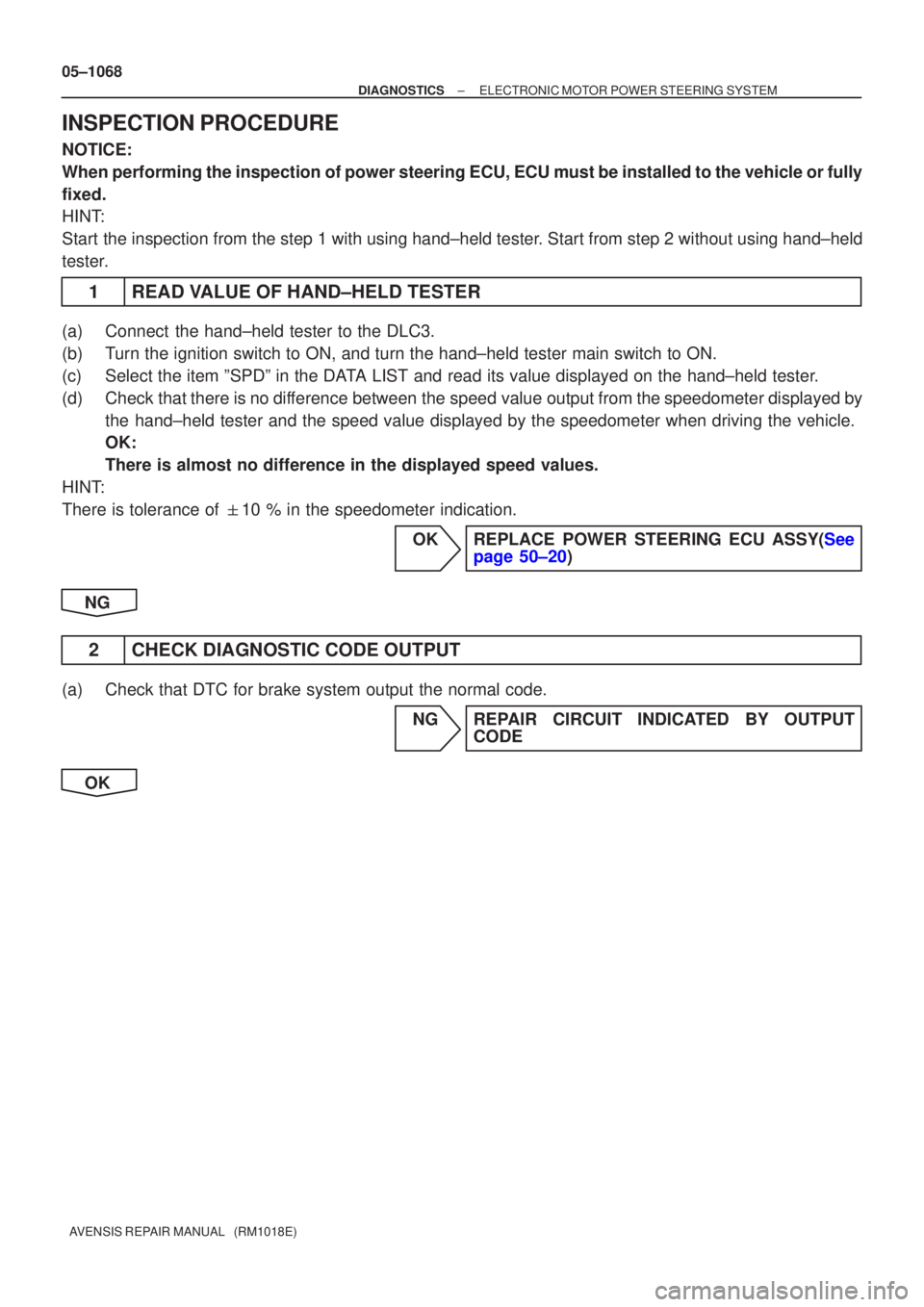
05±1068
±
DIAGNOSTICS ELECTRONIC MOTOR POWER STEERING SYSTEM
AVENSIS REPAIR MANUAL (RM1018E)
INSPECTION PROCEDURE
NOTICE:
When performing the inspection of power steering ECU, ECU must be instal\
led to the vehicle or fully
fixed.
HINT:
Start the inspection from the step 1 with using hand±held tester. Start from step 2 without using hand±held
tester.
1READ VALUE OF HAND±HELD TESTER
(a)Connect the hand±held tester to the DLC3.
(b)Turn the ignition switch to ON, and turn the hand±held tester main swi\
tch to ON.
(c)Select the item ºSPDº in the DATA LIST and read its value displayed on the hand±held tester.
(d)Check that there is no difference between the speed value output from the speedometer displayed by the hand±held tester and the speed value displayed by the speedometer wh\
en driving the vehicle.
OK:
There is almost no difference in the displayed speed values.
HINT:
There is tolerance of �10 % in the speedometer indication.
OKREPLACE POWER STEERING ECU ASSY(Seepage 50±20)
NG
2 CHECK DIAGNOSTIC CODE OUTPUT
(a) Check that DTC for brake system output the normal code. NG REPAIR CIRCUIT INDICATED BY OUTPUTCODE
OK
Page 1183 of 5135

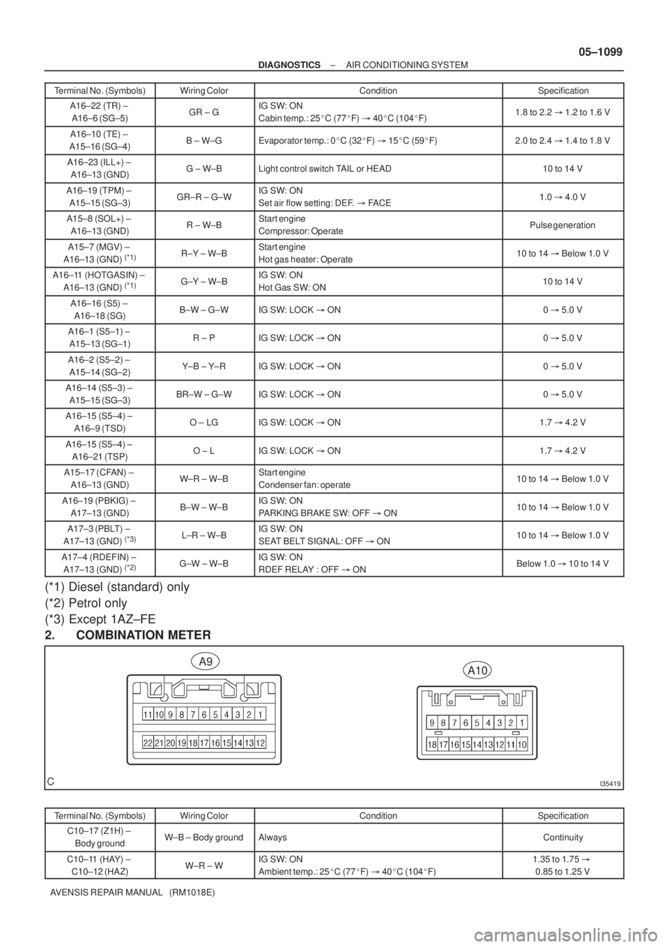
I35419
A10A9
± DIAGNOSTICSAIR CONDITIONING SYSTEM
05±1099
AVENSIS REPAIR MANUAL (RM1018E)Terminal No. (Symbols)Specification Condition Wiring Color
A16±22 (TR) ±
A16±6 (SG±5)GR ± GIG SW: ON
Cabin temp.: 25�C (77�F) � 40�C (104�F)1.8 to 2.2 � 1.2 to 1.6 V
A16±10 (TE) ±
A15±16 (SG±4)B ± W±GEvaporator temp.: 0�C (32�F) � 15�C (59�F)2.0 to 2.4 � 1.4 to 1.8 V
A16±23 (ILL+) ±
A16±13 (GND)G ± W±BLight control switch TAIL or HEAD10 to 14 V
A16±19 (TPM) ±
A15±15 (SG±3)GR±R ± G±WIG SW: ON
Set air flow setting: DEF. � FACE1.0 � 4.0 V
A15±8 (SOL+) ±
A16±13 (GND)R ± W±BStart engine
Compressor: OperatePulse generation
A15±7 (MGV) ±
A16±13 (GND) (*1)R±Y ± W±BStart engine
Hot gas heater: Operate10 to 14 � Below 1.0 V
A16±11 (HOTGASIN) ±
A16±13 (GND) (*1)G±Y ± W±BIG SW: ON
Hot Gas SW: ON10 to 14 V
A16±16 (S5) ±
A16±18 (SG)B±W ± G±WIG SW: LOCK � ON0 � 5.0 V
A16±1 (S5±1) ±
A15±13 (SG±1)R ± PIG SW: LOCK � ON0 � 5.0 V
A16±2 (S5±2) ±
A15±14 (SG±2)Y±B ± Y±RIG SW: LOCK � ON0 � 5.0 V
A16±14 (S5±3) ±
A15±15 (SG±3)BR±W ± G±WIG SW: LOCK � ON0 � 5.0 V
A16±15 (S5±4) ±
A16±9 (TSD)O ± LGIG SW: LOCK � ON1.7 � 4.2 V
A16±15 (S5±4) ±
A16±21 (TSP)O ± LIG SW: LOCK � ON1.7 � 4.2 V
A15±17 (CFAN) ±
A16±13 (GND)W±R ± W±BStart engine
Condenser fan: operate10 to 14 � Below 1.0 V
A16±19 (PBKIG) ±
A17±13 (GND)B±W ± W±BIG SW: ON
PARKING BRAKE SW: OFF � ON10 to 14 � Below 1.0 V
A17±3 (PBLT) ±
A17±13 (GND) (*3)L±R ± W±BIG SW: ON
SEAT BELT SIGNAL: OFF � ON10 to 14 � Below 1.0 V
A17±4 (RDEFIN) ±
A17±13 (GND) (*2)G±W ± W±BIG SW: ON
RDEF RELAY : OFF � ONBelow 1.0 � 10 to 14 V
(*1) Diesel (standard) only
(*2) Petrol only
(*3) Except 1AZ±FE
2. COMBINATION METER
Terminal No. (Symbols)Wiring ColorConditionSpecification
C10±17 (Z1H) ±
Body groundW±B ± Body groundAlwaysContinuity
C10±11 (HAY) ±
C10±12 (HAZ)W±R ± WIG SW: ON
Ambient temp.: 25�C (77�F) � 40�C (104�F)1.35 to 1.75 �
0.85 to 1.25 V