Page 846 of 5135
05±736
±
DIAGNOSTICS ABS WITH EBD SYSTEM
AVENSIS REPAIR MANUAL (RM1018E)
INSPECTION PROCEDURE
1RECONFIRM DTC
(a)Check if other DTCs are detected (See page 05±699). YES REPAIR CIRCUIT INDICATED BY OUTPUTCODE
NO
REPLACE BRAKE ACTUATOR ASSY(See page 32±54)
Page 847 of 5135
F45088GNDGNDIG1
±
DIAGNOSTICS ABS WITH EBD SYSTEM
05±733
AVENSIS REPAIR MANUAL (RM1018E)
DTCC1300/62SKID CONTROL ECU MALFUNCTION
CIRCUIT DESCRIPTION
DTC No.DTC Detecting ConditionTrouble Area
C1300/62Internal control unit of skid control ECU failure.�ECU
INSPECTION PROCEDURE
1RECONFIRM DTC
ADTC C1300/62
BExcept DTC C1300/62
BREPAIR CIRCUIT INDICATED BY OUTPUT
CODE
A
2INSPECT SKID CONTROL ECU CONNECTOR(IG1 TERMINAL VOLTAGE)
IN CASE OF USING HAND±HELD TESTER:
(a)Check the voltage condition, which is output from the ECU and displayed \
on the hand±held tester. OK:
ºNormalº is displayed.
IN CASE OF NOT USING HAND±HELD TESTER:
(a)Disconnect the skid control ECU connector.
(b)Turn the ignition switch ON.
(c)Measure the voltage between terminals IG1 and GND ofthe skid control ECU harness side connector.
OK:
Voltage: 10 to 14 V
OKREPLACE BRAKE ACTUATOR ASSY (See page 32±54)
NG
0577W±04
Page 851 of 5135

F45088GNDGNDSTP
05±732
±
DIAGNOSTICS ABS WITH EBD SYSTEM
AVENSIS REPAIR MANUAL (RM1018E)
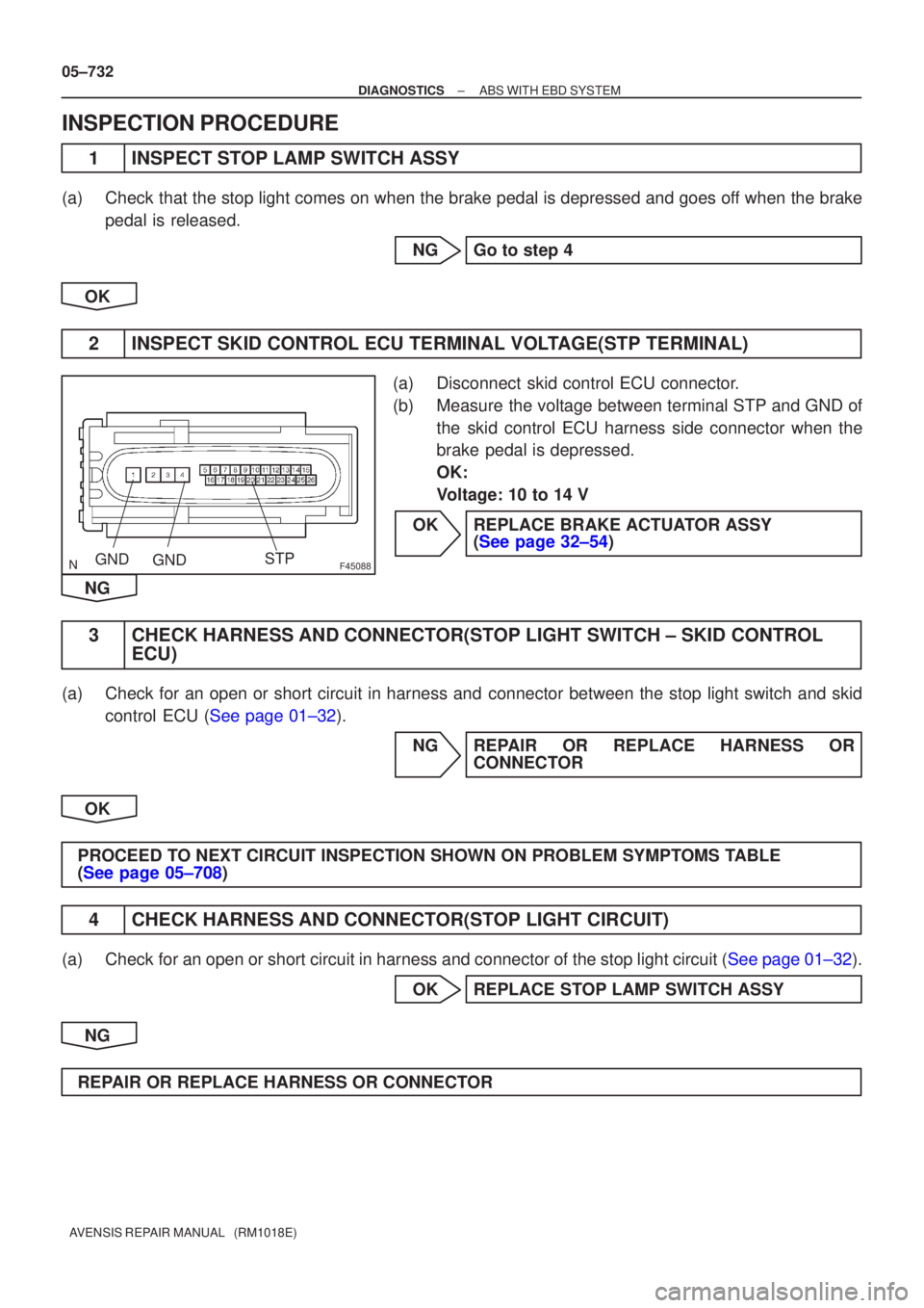
INSPECTION PROCEDURE
1INSPECT STOP LAMP SWITCH ASSY
(a)Check that the stop light comes on when the brake pedal is depressed and goes\
off when the brake pedal is released.
NGGo to step 4
OK
2INSPECT SKID CONTROL ECU TERMINAL VOLTAGE(STP TERMINAL)
(a)Disconnect skid control ECU connector.
(b)Measure the voltage between terminal STP and GND of the skid control ECU harness side connector when the
brake pedal is depressed.
OK:
Voltage: 10 to 14 V
OKREPLACE BRAKE ACTUATOR ASSY (See page 32±54)
NG
3 CHECK HARNESS AND CONNECTOR(STOP LIGHT SWITCH ± SKID CONTROL ECU)
(a) Check for an open or short circuit in harness and connector between the stop light switch and skid
control ECU (See page 01±32).
NG REPAIR OR REPLACE HARNESS ORCONNECTOR
OK
PROCEED TO NEXT CIRCUIT INSPECTION SHOWN ON PROBLEM SYMPTOMS TABLE
(See page 05±708)
4 CHECK HARNESS AND CONNECTOR(STOP LIGHT CIRCUIT)
(a)Check for an open or short circuit in harness and connector of the stop light\
circuit (See page 01±32). OK REPLACE STOP LAMP SWITCH ASSY
NG
REPAIR OR REPLACE HARNESS OR CONNECTOR
Page 852 of 5135

±
DIAGNOSTIC SABS WITH EBD & BA & TRC & VSC SYSTEM
05±807
AVENSIS RE PAIR MANUAL (RM1018E)
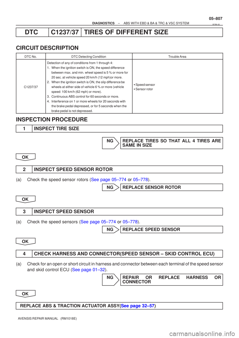
DT C C1237/3 7TIRE S OF DIFFERENT SIZE
CIRCUI T DESCRIPTION
DT C No.DTC Detecting ConditionTrouble Area
C1237/37
Detection of any of conditions from 1 through 4:
1. When the ignition switch is ON, the speed di fference
between max. and min. wheel speed is 5 % or more for
20 sec. at vehicle speed 20 km/h (12 mph)or more.
2 . When the ignition switch is ON, the slip di fference be
wheels at either side of vehicle 6 % or more (vehicle
speed: 100 km/h (62 mph) or more).
3 . Continuous ABS control for 60 seconds or more.
4 . Interference on 1 or more wheels for 20 seconds with
the brake pedal depressed, or for 5 seconds when the
brake pedal is not depressed.
�Speed sensor
� Senso rrotor
INSPECTIO N PROCEDURE
1 INSPEC T TIRE SIZE
N G REPLAC E TIRES SO TH AT ALL 4 TIRES ARE
SAM E IN SIZE
OK
2 INSPECT SPEED SENSOR RO TOR
(a ) Check the speed sensor rotors ( See page 05±774 or 05±778 ).
N G REPLACE SENSOR RO TOR
OK
3 INSPECT SPEED SENSOR
(a) Check the speed sensors ( See page 05±774 or 05±778 ).
N G REPLACE SPEED SENSOR
OK
4 CHECK HARNESS AND CONNEC TOR(SPEED SENSOR ± SKID CONTROL ECU)
(a ) Chec k for an open or short circuit in harness and connector between each terminal of the speed sensor
an d skid control ECU ( See page 01±32).
N G REPAIR OR REPLACE HARNESS OR
CONNEC TOR
OK
REPLAC E ABS & TRACTION ACTU ATOR ASSY( See page 32±57 )
05786±02
Page 853 of 5135
± DIAGNOSTICSABS WITH EBD & BA & TRC & VSC SYSTEM
05±805
AVENSIS REPAIR MANUAL (RM1018E)
DTC C1225/25 SMC SOLENOID CIRCUIT
DTC C1226/26 SMC SOLENOID CIRCUIT
DTC C1227/27 SRC SOLENOID CIRCUIT
DTC C1228/28 SRC SOLENOID CIRCUIT
CIRCUIT DESCRIPTION
The solenoid goes on when receiving signals from the ECU and controls the pressure action on the wheel
cylinders to control the braking force.
DTC No.DTC Detecting ConditionTrouble Area
C1225/25Open or short in SMC1 circuit.�Brake actuator
�SMC1 circuit
C1226/26Open or short in SMC2 circuit.�Brake actuator
�SMC2 circuit
C1227/27Open or short in SRC1 circuit.�Brake actuator
�SRC1 circuit
C1228/28Open or short in SRC2 circuit.�Brake actuator
�SRC2 circuit
05785±02
Page 882 of 5135

0542T±04
05±772
±
DIAGNOSTICS ABS WITH EBD & BA & TRC & VSC SYSTEM
AVENSIS REPAIR MANUAL (RM1018E)
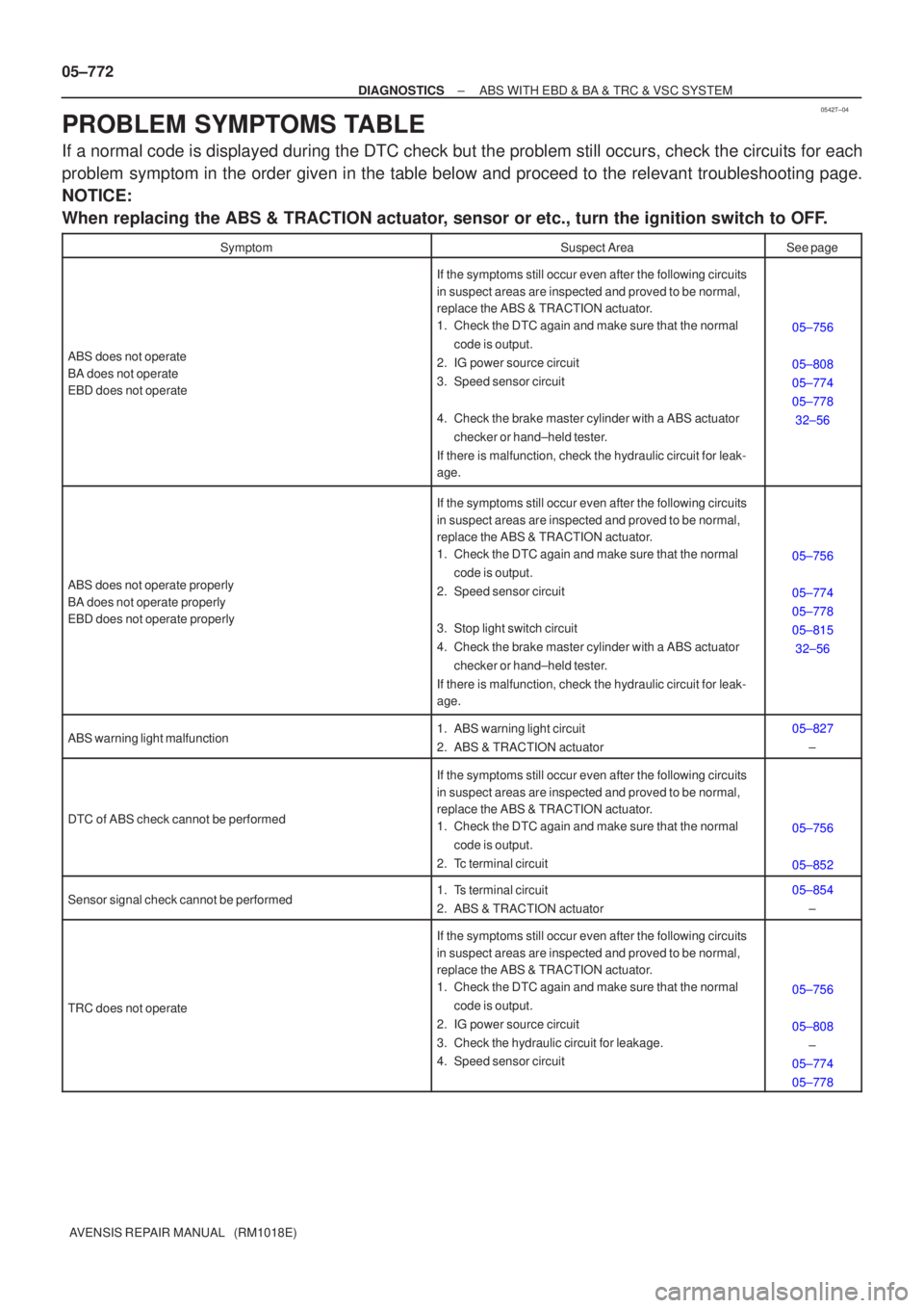
PROBLEM SYMPTOMS TABLE
If a normal code is displayed during the DTC check but the problem still o\
ccurs, check the circuits for each
problem symptom in the order given in the table below and proceed to the releva\
nt troubleshooting page.
NOTICE:
When replacing the ABS & TRACTION actuator, sensor or etc., turn the ignition switch to OFF.
SymptomSuspect AreaSee page
ABS does not operate
BA does not operate
EBD does not operate
If the symptoms still occur even after the following circuits
in suspect areas are inspected and proved to be normal,
replace the ABS & TRACTION actuator.
1. Check the DTC again and make sure that the normal code is output.
2. IG power source circuit
3. Speed sensor circuit
4. Check the brake master cylinder with a ABS actuator checker or hand±held tester.
If there is malfunction, check the hydraulic circuit for leak-
age.
05±756
05±808
05±774
05±778 32±56
ABS does not operate properly
BA does not operate properly
EBD does not operate properly
If the symptoms still occur even after the following circuits
in suspect areas are inspected and proved to be normal,
replace the ABS & TRACTION actuator.
1. Check the DTC again and make sure that the normal code is output.
2. Speed sensor circuit
3. Stop light switch circuit
4. Check the brake master cylinder with a ABS actuator checker or hand±held tester.
If there is malfunction, check the hydraulic circuit for leak-
age.
05±756
05±774
05±778
05±815 32±56
ABS warning light malfunction1. ABS warning light circuit
2. ABS & TRACTION actuator05±827 ±
DTC of ABS check cannot be performed
If the symptoms still occur even after the following circuits
in suspect areas are inspected and proved to be normal,
replace the ABS & TRACTION actuator.
1. Check the DTC again and make sure that the normal code is output.
2. Tc terminal circuit
05±756
05±852
Sensor signal check cannot be performed1. Ts terminal circuit
2. ABS & TRACTION actuator05±854 ±
TRC does not operate
If the symptoms still occur even after the following circuits
in suspect areas are inspected and proved to be normal,
replace the ABS & TRACTION actuator.
1. Check the DTC again and make sure that the normal code is output.
2. IG power source circuit
3. Check the hydraulic circuit for leakage.
4. Speed sensor circuit
05±756
05±808 ±
05±774
05±778
Page 884 of 5135

0542S±04
C94401
05±770
± DIAGNOSTICSABS WITH EBD & BA & TRC & VSC SYSTEM
AVENSIS REPAIR MANUAL (RM1018E)
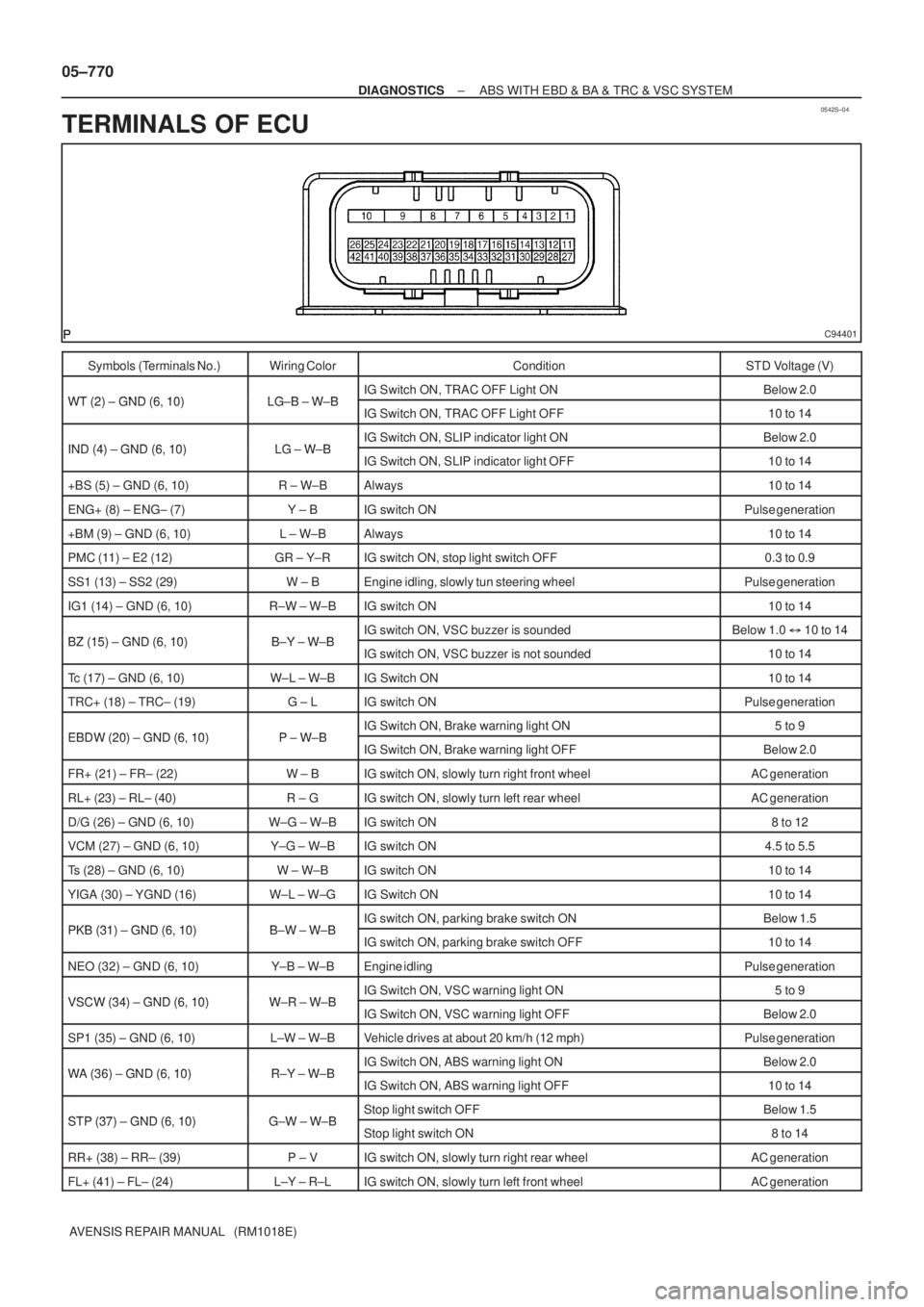
TERMINALS OF ECU
Symbols (Terminals No.)Wiring ColorConditionSTD Voltage (V)
WT (2) GND (6 10)LG B W BIG Switch ON, TRAC OFF Light ONBelow 2.0WT (2) ± GND (6, 10)LG±B ± W±BIG Switch ON, TRAC OFF Light OFF10 to 14
IND (4) GND (6 10)LG W BIG Switch ON, SLIP indicator light ONBelow 2.0IND (4) ± GND (6, 10)LG ± W±BIG Switch ON, SLIP indicator light OFF10 to 14
+BS (5) ± GND (6, 10)R ± W±BAlways10 to 14
ENG+ (8) ± ENG± (7)Y ± BIG switch ONPulse generation
+BM (9) ± GND (6, 10)L ± W±BAlways10 to 14
PMC (11) ± E2 (12)GR ± Y±RIG switch ON, stop light switch OFF0.3 to 0.9
SS1 (13) ± SS2 (29)W ± BEngine idling, slowly tun steering wheelPulse generation
IG1 (14) ± GND (6, 10)R±W ± W±BIG switch ON10 to 14
BZ (15) GND (6 10)BY WBIG switch ON, VSC buzzer is soundedBelow 1.0 �10 to 14BZ (15) ± GND (6, 10)B±Y ± W±BIG switch ON, VSC buzzer is not sounded10 to 14
Tc (17) ± GND (6, 10)W±L ± W±BIG Switch ON10 to 14
TRC+ (18) ± TRC± (19)G ± LIG switch ONPulse generation
EBDW (20) GND (6 10)PWBIG Switch ON, Brake warning light ON5 to 9EBDW (20) ± GND (6, 10)P ± W±BIG Switch ON, Brake warning light OFFBelow 2.0
FR+ (21) ± FR± (22)W ± BIG switch ON, slowly turn right front wheelAC generation
RL+ (23) ± RL± (40)R ± GIG switch ON, slowly turn left rear wheelAC generation
D/G (26) ± GND (6, 10)W±G ± W±BIG switch ON8 to 12
VCM (27) ± GND (6, 10)Y±G ± W±BIG switch ON4.5 to 5.5
Ts (28) ± GND (6, 10)W ± W±BIG switch ON10 to 14
YIGA (30) ± YGND (16)W±L ± W±GIG Switch ON10 to 14
PKB (31) GND (6 10)BW WBIG switch ON, parking brake switch ONBelow 1.5PKB (31) ± GND (6, 10)B±W ± W±BIG switch ON, parking brake switch OFF10 to 14
NEO (32) ± GND (6, 10)Y±B ± W±BEngine idlingPulse generation
VSCW (34) GND (6 10)WR WBIG Switch ON, VSC warning light ON5 to 9VSCW (34) ± GND (6, 10)W±R ± W±BIG Switch ON, VSC warning light OFFBelow 2.0
SP1 (35) ± GND (6, 10)L±W ± W±BVehicle drives at about 20 km/h (12 mph)Pulse generation
WA (36) GND (6 10)RY WBIG Switch ON, ABS warning light ONBelow 2.0WA (36) ± GND (6, 10)R±Y ± W±BIG Switch ON, ABS warning light OFF10 to 14
STP (37) GND (6 10)GW WBStop light switch OFFBelow 1.5STP (37) ± GND (6, 10)G±W ± W±BStop light switch ON8 to 14
RR+ (38) ± RR± (39)P ± VIG switch ON, slowly turn right rear wheelAC generation
FL+ (41) ± FL± (24)L±Y ± R±LIG switch ON, slowly turn left front wheelAC generation
Page 886 of 5135
F45132
Battery FL MAINSkid Control ECU
with Actuator
B±G (*1) L (*1)
1 ALT Engine Room R/B No.4 & Engine Room J/B No.4
1
4B
W±BS1
S1 109
+BM
12
1 2
GND1 GND2
S16
W±BW±B
*1: 1AZ±FSE
*2: 1CD±FTVEA4
L (*2)
W (*2)
2 12 33 11B1VSC
ALT Engine Room R/B No.3Engine Room R/B No.1 &
Engine Room J/B No.1
B (*2)
B±G (*1)VSC
± DIAGNOSTICSABS WITH EBD & BA & TRC & VSC SYSTEM
05±825
AVENSIS REPAIR MANUAL (RM1018E)
DTC C1350/51 PUMP MOTOR IS LOCKED/OPEN CIRCUIT
IN PUMP MOTOR GROUND
CIRCUIT DESCRIPTION
DTC No.DTC Detecting ConditionTrouble Area
C1350/51
When any of the following 1 through 3 is detected.
1. No motor voltage supply within 0.08 sec. after actuation
starts the motor relay.
2. A high level of motor voltage when actuation does not
starts the motor relay for more than 2.5 sec.
3. The pump motor voltage is high level for a certain time
after the motor relay has elapsed.
�Brake actuator pump motor
�ABS motor relay circuit
WIRING DIAGRAM
0578A±02